
Summary of Contents for MobileVision MV-BC1
- Page 1 Owner’s / Installation Manual Digital Wireless Safety Camera Monitor System Model: MV-BC1 For Technical Assistance, please call (310) 735-2000, or visit www.magnadyne.com...
-
Page 2: Table Of Contents
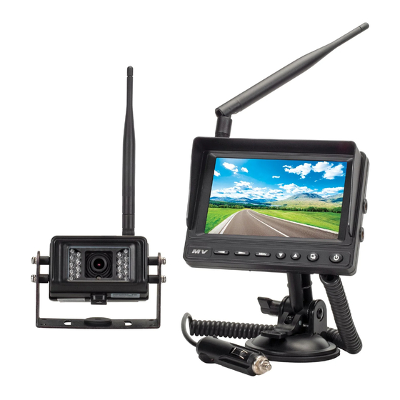
Camera Mounting Template ..................... 19 Introduction Congratulations on the purchase of the Mobilevision 5” Monitor Camera System. This system has been designed to provide years of trouble-free operation. The information in this manual provides detailed instruction on how to properly install, operate and maintain your new MV-BC1 camera system. -
Page 3: Monitor Installation
Monitor Installation Antenna Mounting Thumb Wheel Locking Thumb Wheel Upper Tilt / Swivel Vehicle Power Adapter Lower Tilt Pull Lever Suction Cup Mounting Base Incorrect Correct Incorrect Correct Figure C Figure B Figure A 1. Loosen the mounting thumb wheel on the suction cup mounting base, so the mounting nut attached to the monitor mounting thumb wheel can slide completely into the monitor’s base mounting slot (Figure A). -
Page 4: Mobilevision Factory Pre Wired Installation
MobileVision Factory Pre Wired Installation If your vehicle is Pre Wired and ready for the MV-BC1 Camera / Monitor System the back of your vehicle will have a MobileVision Pre Wired plate in this general location and the plate will look like the below illustration. - Page 5 MobileVision Factory Pre Wired Installation (continued) Vehicle Surface Gasket Figure A Screws from Bracket Camera & Bracket Assembly Connect the camera power lead to the power lead in vehicle. Screws from Bracket Camera Adjustment Screws (loosen only, do not remove)
-
Page 6: Non-Mobilevision Pre Wired Installation
MobileVision, install the MV-BC1 Camera / Monitor System using the following steps. DISCONNECT VEHICLE POWER BEFORE STARTING INSTALLATION How to Identify if your vehicle has a camera pre wired kit and ready for MV-BC1 installation. Option A - Installation If your vehicle has a pre wired install cover plate with the above illustrated shape follow these steps to install the camera. - Page 7 Non-MobileVision Factory Pre Wired Installation (continued) Gasket Figure A Power adapter harness Connect the power adapter harness lead to the vehicles pre wired power lead Screws from Bracket Camera & Connect the camera power lead Bracket Assembly to the power adapter harness...
- Page 8 • Unscrew the plate from the back of the vehicle. • Unattach power lead from pre wired plate. • Align supplied MobileVision PVC gasket with predrilled holes pulling vehicles power lead through center 3/4” hole. • Use supplied adapter power cable to connect camera and vehicle power leads.
- Page 9 Non-MobileVision Factory Pre Wired Installation (continued) Gasket Figure A Supplied adapter harness Connect the adapter harness lead to the vehicles pre wired power lead Screws from Bracket Camera & Bracket Assembly Connect the camera power lead to the supplied adapter harness...
-
Page 10: New Installation - No Factory Pre Wires Present
New Installation - No Factory Pre Wires Present DISCONNECT VEHICLE POWER BEFORE STARTING INSTALLATION Mounting Location 1) Mounting Location: • Identify a suitable mounting location near the roof line centered on the rear of the vehicle 2 or more inches above or below running lights to prevent degrading image and reducing night vision. - Page 11 New Installation - No Factory Pre Wires Present (continued) 4) Mounting Camera: • Make sure vehicles power lead passes through the gasket’s large center hole. Use precaution to prevent lead from falling into vehicle. • Connect the camera and vehicle power leads. Make sure the connectors are securely twist-locked together.
-
Page 12: Button Operations
Button Operations 1) Multifunction Button - Volume Down in camera view. - Left selection for menu settings. 2) Multifunction Button - Volume Up in camera view. - Right selection for menu settings 3) Multifunction Button Push to open menu, push again to close menu. Push and hold for 3 seconds to enter camera pairing mode. -
Page 13: Monitor Menu Operations
Monitor Menu Operation 1) Picture Setting: Enter the main menu, choose Picture and press OK. Brightness: 0-10 (Press Left/Right to adjust) Contrast: 0-10 (Press Left/Right to adjust) Color: 0-10 (Press Left/Right to adjust) 2) Mirror/Normal Image Settings: Set the CAM1/CAM2 Image in 4 modes. 3) Auto Scan Setting: A) Set CAM1/CAM2 auto scan mode on/off. -
Page 14: Camera Pairing
Camera Pairing • The camera must be powered off prior to pairing procedure (disconnected from power) • Turn on the monitor then press and hold the “M/P” button on the monitor’s front panel for a few seconds. The monitor screen will display the camera selections with CAM 1 highlighted. -
Page 15: Maintenance
Maintenance Although this monitor requires little care, you can still maintain its condition and performance by following these steps: • Keep the system away from excessive moisture, extreme heat or cold, and magnetic fields. • Occasionally clean the monitor screen with a damp soft cloth. Should you experience any problem with the system please refer to the troubleshooting guide prior to returning your system for repair. -
Page 16: Specifications
Specifications MobileVision’s M160-W Specifications Display Device: Color TFT-LCD Size: 5” Digital Screen Operation Frequency: 2.4GHz Receiving Sensitivity: ≤86dBm (1MHZ QPSK MD300RE) Resolution: 800 x (RGB) x 480 View Angle (LR/UD): L/R: 70/70 U/D: 50/70 Contrast Ratio: 300:1 Luminance (cd/m Response Time (ms):... -
Page 17: Warning / Cautions
Do not use any features of this system to the extent it distracts you from safe driving. Your first priority while driving should always be the safe operation of your vehicle. MobileVision will not accept any responsibility whatsoever for accidents and/or injuries resulting from failure to observe these precautions or safety instructions Cautions •... -
Page 18: Warranty
Warranty ONE (1) YEAR LIMITED WARRANTY Magnadyne Corporation or its authorized agents will within one year from the date of sale to you, repair, replace or refund the retail sales price of said product or any part thereof, at the option of the Magnadyne Corporation or its authorized agents, if said product or part is found defective in materials or workmanship, when properly connected and operating on the correct power requirements designated for the specific product. -
Page 19: Camera Mounting Template
Camera Mounting Template Cut Out Template on Dotted Line Install Camera Mounting Screws Here (x4) Drill 3/4” Hole Here... - Page 20 Copyright © 2020 Magnadyne Corp. MV-BC1_IM_UM Rev. A 1-14-20...
Need help?
Do you have a question about the MV-BC1 and is the answer not in the manual?
Questions and answers