Table of Contents
Advertisement
Quick Links
ITT Mackay Marine
A DIVISION OF ITT TELECOMMUNICATIONS CORPORATION
INSTRUCTION MANUAL
FOR
3031A/EB3039
SYNTHESIZED RECEIVERS
PUBLICATION rW.
600198-823-001
ISSUE 2
NOVH1BER, 1979
ITT
Mackay Marine
Main Office: 2912 Wake Forest Road, Raleigh, North Carolina 27611 U.S.A.
Telephone: (919) 828·4441
W.U. Telex 579451
(cJ INTERNATIONAL TELEPHONE AND TELEGRAPH CORPORATION
ALL RIGHTS RESERVED
Advertisement
Table of Contents

Summary of Contents for ITT Mackay Marine 3031A
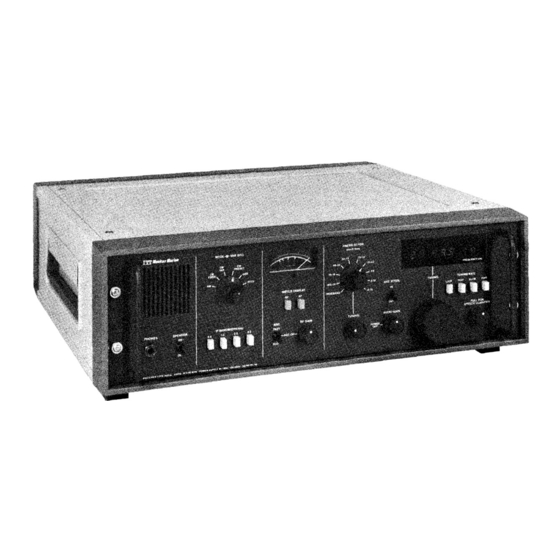
- Page 1 ITT Mackay Marine A DIVISION OF ITT TELECOMMUNICATIONS CORPORATION INSTRUCTION MANUAL 3031A/EB3039 SYNTHESIZED RECEIVERS PUBLICATION rW. 600198-823-001 ISSUE 2 NOVH1BER, 1979 Mackay Marine Main Office: 2912 Wake Forest Road, Raleigh, North Carolina 27611 U.S.A. Telephone: (919) 828·4441 W.U. Telex 579451...
- Page 2 WARRANTY AND LIMITATION OF LIABILITY ITT warrants (A.) for equipment sold hereunder that for a period of 18 months from ITT's shipment date or 12 months from Buyer's acceptance, whichever ends first, equipment (except for vacuum tubes, fuses and dial lights which are warranted for90 days) shall be free from defects in material and workmanship and conform to the equipment's specifications;...
- Page 4 NOTICE ITT MACKAY MARINE reserves the right to make changes to the equipment without notice. PROPRIETARY STATEMENT The information in this publi cation is the property of ITT MACKAY MARINE. This information is for the p urchaser's use only and may not be reproduced with...
- Page 5 SAFETY NOTICE The voltages present in this equipment may cause BURNS or INJURY. Use caution when servicing the equipment. When power-off maintenance is performed, disconnect the power cord, if practicable, s o that the equipment cannot be accidentally energized.
- Page 6 Mackay Marine synthesized, scan tuned receivers. The first tab section describes the standard 3031A receiver. Each succeeding tab section describes the unique features of each of the other receivers in this series; these tab sections must be used in conjunction with the 3031A tab section.
-
Page 7: Table Of Contents
CONTENT S PAGE SECTION GENERAL DESCRIPTION Scope • Introduction Technical Specifications Dimensions and \4eigh t Receiver Configurations 2. 1 INSTALLATION Genera 2. 1 Rear Panel Terminal Board Filter FLl Potentiometer through AC Operation Bat tery Connection 3. 1 OPERATION 3. 1 General 3. - Page 8 CONTENTS continued PAGE SECTION 4.15 Rear Panel Interconnect PC Board 4. IS 4. 7 Front Panel Interconnect PC Board 4.16 Scan Tune Module 4. 16 Genera 4. 1 7 Circuit Description 4.20 4. 9 Opto-Coupler PC Board 4.20 4. 10 Display Decoder PC Board MAINTEN ANCE General...
-
Page 11: General Description
Included in this manual are sections on general description, operation, circuit description, maintenance, replaceable and spare parts, drawings. INTRODUCTION • The 3031A is a fully synthesized, dual conversion, superheterodyne, maritime and fixed station communications receiver. It covers a continuous frequency range of 15 k H z to 29.99999 M H z in 10 Hz increments and is scan tuned. - Page 13 With the antenna input connector ter Internally generated minated in a 50 ohm load and the pre spurious responses selector set to WIDEBAND, the maximum level of internally generated spuri ous responses does not exceed 0.13 microvolt (-124 dBm) equi lvalent input level in any marine band, or 0.5 microvolt outside marine bands.
-
Page 14: Dimensions And \4Eigh T
Range: less than 6 dB change in output Automatic gain control for input signal variation from l micro volt to 100 microvolts (100 dB measured in SSB mode with preselector set to WIDEBAND (50 ohm input). Attack time: 10 milliseconds nominal. Decay time: FAST - 150 milliseconds nom- inal. - Page 17 TABLE 1.2 RECEIVER CONFIGURATIONS ("/"\ r--. ..::r ("/"\ ..::r L.i\ "'"' 0"\ Standard 3031A 3031A For Use in IMM Consoles 3031 for STK EB3039 Front Black Panel Greige Front -..J Panel Black Handles Chrome Handles Preselector w ith All-Band Preamp...
-
Page 19: Installation
Installation of the receiver is quick and simple as the unit is completely wired, calibrated, and tested before shipment from the factory. When purchased as part of an ITT Mackay Marine communications console, the receiver is shipped installed in the console. The receiver can be installed in its own (optional) cabinet for table-top mounting or can be installed in a communications console;... -
Page 20: Potentiometer R4 Through R7
CAUTION Turn off the receiver and dis connect the power cord before making connections to TBl. For connection to a ohm external speaker, connect the speaker leads to pin ohm audio output) and pin or pin 6 (ground). The front panel on/off (3.2 speaker switch does not affect the external speaker. -
Page 21: Battery Connection
Slide the cover all the way to the right and replace the power cord. BATTERY CONNECTION The 6.25 volt Nicad battery located inside the receiver on the side panel powers the circuitry which enables the 3031A to automatically return to the dialed frequency when receiver power has been turned off. This battery must be connected when the 3031A is initially placed into service. - Page 23 6VOLT ANTENNA INPUT REGULATOR Et>® AC FUSE � (±) \.11 (£) AC VOLT AGE BOARD 110/220 VOLT AC INPUT (power cord provided) Pins 1/3 - bal. 600 ohm line out Pin 2 - ground 3.2 ohm audio out mute in (ground to mute receiver) Pin 6 - ground Pins 7/8 - spare Figure 2.2.
- Page 26 RF/AF METER DISPLAY The RF/AF METER DISPLAY pushbuttons select the rf and af input levels for display on. the meter. The rf level shows AGC voltage in dB above microvolt rms while the af level shows the 600 ohm line voltage in dBm milliwatt equals 0 dBm).
-
Page 27: Automatic Gain Control
AUDIO GAIN/POWER OFF The AUDIO GAIN/POWER OFF control knob turns the power on and off and adjust the audio level to the speaker and headphones. (Turn the knob clockwise to turn on the receiver and increase the gain; turn the knob counterclockwise to decrease the gain and turn off the receiver.) PULL FOR SPEECH CLARIFIER When pulled, the PULL FOR SPEECH CLARIFIER control knob unlocks the... -
Page 28: Preselector Operation
3. 5 PRESELECTOR OPERATION Above 4 MHz, the PRESELECTOR BAND MHz switch normally is left in the WIDE BAND position as the receiver meets all sensitivity, image, cross modulation, and suprious response specifictaions at this setting. When a sh ort (35 foot whip, for example) antenna is used on frequencies below 4 MHz, a sensitivity improvement can be obtained by using the PRESELECTOR TUNING control as an impedance matching network. -
Page 31: Circuit Description
SECTION 4 CIRCUIT DESCRIPTION 4. 1 GENERAL The 3031A is completely modular in construction with each module housing one or more printed circuit boards. The modules and their functions are as follows. The SIGNAL PATH module provides mixing, filtering, and amplification. - Page 32 The output from the information filter PC board is routed to the 5 MHz i-f PC board which amp! ifies, detects, and processes signals for AGC of the i-f and front end. The reconverted audio signal is applied to the input of the audio amp] ifier PC board which has a gain control amplifier to set final speaker/headphone volume, and a power amplifier stage to boost the low level audio to the desired level (up to 3.5 watts).
-
Page 33: Signal Path Mother Board
The AGC detector drives a de amplifier which has selectable decay-time constants. These decay times of approximately 150 milliseconds and 1.5 seconds permit optimum reception of stable or rapidly fading signals in all receiver modes. Attack time for the circuit is about 10 milliseconds. The AGC is applied to two 5 MHz i-f stages and to the 92 MHz i-f stage through a delay circuit. - Page 34 provides a very broadband, 50 ohm termination to the mixer (50�5° over 1 to 100 MHz, typical); this is the key to obtaining good mixer performance. In addition, L.O. injection amplifier QlO has approximately 50 ohms driving impedance. These criteria maintain the high intercept. The U431 is followed by a 92.010 MHz two-pole crystal filter which prevents interference to subsequent stages from signals removed by more than 30 kHz.
-
Page 35: Information Filter Pc Board
justable AGC output at P13 is derived from the i-f AGC line through poten tiometer R46. R46 is adjusted to set the cut-in voltage of the rf AGC on the front end PC board. The AGC is switched off by applying 12 volts to Pll. With the AGC off, manual gain control can be applied through P12 which is routed to the i-f stages through CR6, Qll, and U3-B. -
Page 36: Synthesizer Mother Board
reference oscillator, but is injected simultaneously into the major loop mixer and into the signal path second mixer. The two mixers function so that vari ations in the 87 MHz frequency are cancelled out at the final 5 MHz i-f. this way the overall stability of the synthesizer reference, in parts per mi Ilion, is maintained, while allowing the lower stability 87 MHz source to be used. - Page 38 The 5 MHz signal is fed from U 2 to emitter follower Q4. The low impedance from Q41s emitter drives the 5 0 ohm lowpass filter, consisting of L6, L7, and C 20 through C 2 4 , through Rl6. The filter•s output goes to a 22 dB pad con...
- Page 39 the frequency determing network . Adjustment is via a potentiometer mounted on the receiver front panel. When a BFO mode is selected, the 5.000 M H z standard is turned off and the 5 M H z BFO PC board is energized. Simultaneously, the BFO is connected to the signal path through a TTL logic switch on the low frequency reference PC board.
- Page 40 Counter Ull is always loaded with a count of 10 (hardwired). Counters UlO, U9, and U8 are loaded with the 10 kHz, 1 kHz, and 100 Hz digits, respec Counter U7 is loaded with the desired 10 Hz digit and, in conjunc tively.
- Page 41 The VCO, consisting of JFET Ql, Ll, CRl, C2, C3, and associated circuitry is a Colpitts-type oscillator which can be pulled from 87.5 MHz to approxi mately 89 MHz by varying the control voltage at TP2. change in the de voltage at this point changes the bias on varicap CRl, in turn changing the VCO tank capacitance and thus the VCO frequency.
-
Page 42: Major Loop/Major Loop Vco Pc Boards
impedance 2.2-volt source. This causes the collector voltage of Q6 and Q7 to drop, lowering the VCO frequency to reestablish lock. The output of U2 at TPS again goes to a high impedance when lock is achieved. The loop translator PC board also has a lock detector. When the loop is locked, pins 2, 11, 4, and 13 of phase detector U2 are at approximately 4 volts. - Page 43 Inductor LS, the tank coil, has been adjusted to calibrate the asci llator. Capacitors Cl4 and CIS form a C-transformer, with Cl4 adjusted to provide the correct rf level at the output of the major loop. Transistor Q2 is a common-base rf amplifier which: (I) buffers the VCO to reduce loading, and (2) provides reverse isolation from the major loop and signal path mixers...
-
Page 44: Preselector Module
applied to the V C O . (The V C O frequency must never drop below 88 MHz or the loop wil 1 lock up incorrectly.) If the loop output frequency is low, the counter frequency is low, causing pins 5 and 10 to drop to a low impedance 0.7-volt source. -
Page 45: Power Supply
The preselector also has a low-pass filter which attenuates signals above In particular, this filter provides image suppression because the 30 MHz. first image of the receiver is 184 MHz above the tuned channel frequency. The filter also reduces first local-oscillator feed-through to the antenna connector, to prevent unwanted signal radiation from the receiver. -
Page 46: Scan Tune Module
range, speaker on/off, i-f bandwidth, mode select/BFO adjust, speech clari fier, and scan tuning rate. The LED frequency displays also are mounted in this board. The d isplay decoder PC board, which decodes the synthesizer address and drives the LED display digits, is mounted on the front panel interconnect PC board. Connector Jl on the display decoder PC board connects to the scan tune module output. -
Page 47: Circuit Description 4. 1
(600926-536-001). Scan Tune Counter Board (600927-536-001). Scan Tune Encoder Board The function of this assembly is to provide BCD information to program a fre quency synthesizer and BCD outputs to be decoded and displayed. Circuit Description Scan Tune Encoder Printed Circuit Board The Encoder Board is used to generate clock signal, count direction, count speed, and data retention command inputs to the Counter Board. - Page 48 For counterclockwise rotation (count down) Detector 1 Output Ul/A Pin 4 Detector 2 Output Ul/B Pin 3 Direction Output U2/A Pin 1 The main clock signal (Ul/B Pin 3) is delayed lOO�SEC by network R8, C2 to insure that the direction information at U2/A Pin 3 is stable before counterclocking occurs.
- Page 49 CM OS to TTL buffer/converters U7-UII accept the outputs of the scan tune counters and drive the ?-segment display drivers lo cated on the receiver front panel. The four outputs of the 10 MHz scan tune counter decades are processed by U6/A, U6/B, U6/C and U3/B to generate a 11211 jam input and a preset enable command for the 10 MHz counter decade to control the counter modulus.
-
Page 50: Opto-Coupler Pc Board
In FAST, the clock signal entering via P31 -32 is divided by four in Ul/A, Ul/B and applied to the input of U8, the 100kHz decade. Therefore each four clock pulses increment or decrement the receiver frequency by 100 kHz. All less significant decades remain undisturbed. - Page 51 Thus a BCD digit 11 6 11 address is converted to a 7- 7-segment LED code. segment display code 11 6 11 • Each display is addressed by a 74LS47 display decoder-driver chip. interface is routed through 470 ohm resistors to 1 imit the segment current to about 6 milliamperes.
- Page 53 SECTION MAINTENANCE 5. 1 GENERAL The receiver has been designed to be particularly easy to service. Routine preventative maintenance generally is not required and corrective mainten ance usually consists of substituting plug-in printed circuit b oards or modules. Most of the individual PC boards are grouped and housed in plug-in modules. The individual PC boards within such a module have h andles for easy extrac...
-
Page 54: Printed Circuit Boards
While gently prying with the screwdriver, slide the module to the right until the nipples are clear of the clips and the stop-nut is centered in the hole in the module flange clear of the slot Lift the module straight up and place where desired. Preselector Module Proceed as follows to remove the preselector module. -
Page 55: Routine Maintenance
ROUTINE MAINTENANCE 5. 3 The receiver is factory aligned and is designed to be highly stable. Periodic routine alignment is not necessary* and should not be attempted. Other routine maintenance should be restricted to removing dust, and a visual inspection to ensure that all internal and external connectors are properly seated. -
Page 56: Bfo And Meter Calibration
BFO A ND METER CALIBRATION The BFO and front panel meter can be calibrated by adjusting p otentiometers R4 (BFO) and R5, R6, and R7 (meter) on the rear panel interconnect PC board. The board and locations of R4 through R7 are shown in Figure 5.5. To adjust the BFO, set the BFO MODE control to CW PRESET and tune the receiver to 00000.00 kHz. -
Page 57: Rtty Filter Addition
When the correct level has been obtained at TBl, depress the METER DISPLAY AF pushbutton on the receiver front panel and adjust (audio) to obtain a 0 dBm reading on the front panel meter. meter wi 11 now read co�rectly for 1 ine levels up to +10 dBm. The signal generator must be used to adjust the rf meter (see item e, below). -
Page 59: Troubleshooting Guide
TROUBLESHOOTING GUIDE CAUTION Turn off the power and disconnect the power cord before removing any modules, module covers, or PC boards. SYMPTOM POSSIBLE CAUSE RECOMMENDED ACTION Receiver Receiver power switch on but meter light Power cord not properly connected. Ensure power cord is plugged in. Fuse blown. - Page 62 RECOMMENDED ACTION SYMPTOM POSSIBLE CAUSE Minor loop unlocked. Check for the following: LED on minor loop (on = unlocked) . P25 of minor loop for +5 VDC. P26 of minor loop for +12 VDC. P27 of minor loop for +20 VDC. P3 of minor loop for 1.00000 to 1.09999 MHz waveform.
-
Page 65: Synthesizer
REAR PANEL INTERCONNECT BOARD SIGNAL-PATH MODULE Audio Amplifier Front End Signal Path Mother Board Information Filter 5 MHz IF/AGC SYNTHESIZER MODULE 87 MHz Oscillator Major Loop 5 MHz BFO Low Frequency Reference Loop Translator Minor Loop Synthesizer Mother Board PRESELECTOR SCAN-TUNE MODULE MODULE Scan-Time Encoder... - Page 70 12V REG. TO E6 12V REG · � [ 9 ] TO C2+ 12V TO MODE SWITCH 6V UNREG. REMOVE (11V TYP . ) PLUG TO ( 2 5] [ 32] """ MEASURE [33] l2� 1 f ,.., ,..., ..
-
Page 71: Replaceable Parts
SECTION 6 REPLACEABLE PARTS 3031A 600165-800-00 1 PART NUMBER DESCRIPTION SYMBOL 690012-000-001 Preselector Assembly A 11 690013-000-001 Signal Path Module 690014-000-001 Scan Tune Module 690015-000-001 Synthesizer Module 600048-539-001 Front Panel Assembly 600051-539-001 Rear Panel Assembly 600183-314-025 Capacitor, 9100 uF, 35V... - Page 74 REAR PANEL ASSEMBLY (600051-539-001) DESCRIPTION PART NUMBER SYMBOL Corcom Fi Iter 600070-529-001 Rear Panel Interconnect PCB 600974-536-001 Regulator, 1412, 12V 600301-415-003 Regulator, LAS 1406, 6V 600301-415-002 c4, c6 Capacitor, 600259-314-103 610045-31 9-350 C 3, C 5 Capacitor, *Fuse, 3/4A, 250V, Slo-Bio 600006-396-017 IIOV...
- Page 75 SYNTHESIZER MODULE (690015-000-001) PART NUMBER DESCRIPTION SYMBOL 600925-536-001 Mother Board 600924-536-001 5 MHz BFO PCB 600920-536-001 Low Freq. Reference PCB 600920-536-00l Minor Loop PCB 87 MHz Oscillator PCB 600923-536-001 600919-536-001 Major Loop PCB Major Loop VCO PCB 600918-536-001 (mounted on A6) 600296-415-001 I ntegrated Circuit �A7812C...
- Page 78 SCAN TUNE MODULE (690014-000-001) SYMBOL DESCRIPTION PART NUMBER 6oo92 536-oo 1 Scan Tune Encoder PCB 600926-536-oo 1 Scan Tune Counter PCB...
- Page 79 SCAN TUNE MECHANISM (600052-539-001) DESCRIPTION PART NUMBER SYMBOL 600961-536-001 Opto-Cou pler PCB 600029-620-001 Block, bearing assembly 600172-637-001 Spacer 600052-615-001 Shaft 600007-627-001 Flywheel, front 600008-627-001 Fl ywhee rear 600009-627-001 Disc, chopper 600020-239-001 Ring, retainer 600050-625-001 622004-217-005 Washer, internal tooth, 1/4-20 600050-212-009 Nut-lock, #4-40 Screw,...
-
Page 81: Standard Spare Parts 7
Fuse, 3/8A, 2 5 0V, Slo-Blo 600006-396-012 (for 220VAC operation) Lamp, 12V 6000 5 6-390-001 Additional spar e parts lists which includ e special (optional) spares are availabl e from the ITT Mackay Marine S ervice D epartment. 7. 1... -
Page 83: Schematic And Assembly Drawings Index
SECTION 3 SCHEMATIC AND ASSEMBLY DRAWINGS INDEX DRAWING NUMBER PAGE DESCRIPTION SIGNAL PATH MODULE: 620911-536 8. 15 Front End PCB Schematic Front End PCB Assembly 600911-536 8. 14 620912-536 8. I 7 IF/AGC PCB Schematic IF/AGC PCB Assembly 600912-536 8.16 Information Filter PCB Schematic 620914-536 8.21/... - Page 84 SCHEMATIC AND ASSEMBLY DRAWINGS INDEX (continued) DRAWING NUMBER DESCRIPTION PAGE MISCELLANEOUS: 620961-536 8.39 Opto-Coupler PCB Schematic 600961-536 8.38 Opto-Coupler PCB Assembly 620972-536 Display Decoder PCB Schematic (Part of) 600975-536 Display Decoder PCB Assembly 620972-536 Front Panel Interconnect PCB Schematic 600972-536 Front Panel Interconnect PCB Assembly 600048-539 Front Panel Subassembly...
- Page 85 J� ,--- --- --, " " '" � � -, - ..,. .. - , r- T r - T-, ..1 1 ...L j l_ J_ _j L- .L-' ,.. , �� "" � s•- - - - r----- - : I i ':'!! :SC LEC�...
- Page 88 't.*>' 0 I SPLAY OCCCDER BOARD 600975-536-001 ISS_ MAOC IN USA Mackay Marine A DIVISION M INTERNATIONAL TELEI'HONE AND TELEGRAPH COII I'Oa ATION 2912 WAKE FOREST RD. RALEIGH,N.C. 27611 DlS"PLAY 1>ec.o1>e:� l>c,l> -:BL ( AS6E:fh (p(X) � 7S- 5.3(,...
- Page 90 LIMITED TO 50mA uO CLI'Rll''l SW CONNECT TO OTI-IE.R LOADS. 8:> +20V 9F"O CONT RTTY FOR 3030/31; LSB FOR 3().4{]/41 ITT Mackay Marine · AIMvteiQJII Cl' @:> IHI'I•NAfM)IrrUJ. flll..c>N l AND TILIG.AIIH C:O.POII A TtoN IKHL FOR 3030/31 , 2KHt FOR 3040/41 �_5<£...
- Page 91 A DIV1810N 011' INTERNATIONAL TELEI'HONE AND TELEORAI'H COII I'OI I A TION 2912 WAKE FOREST RD. RALEIGH,N.C. 27611 fJ'Rt=SELEC T()K. (ptXJ9 sY-ti"� (,...
- Page 92 SI-BI oF G900 51-C r;;. R T .::: z Sl-62. LUG. IZ. LUG I LUG. 12 LUG z_ RF\NC.. E fREO 1 - -- -- WIDE BAND 15KHZ.- \OOKI-\2 1. 0 5'- ?< F .0027,-'F l. 0 516�F 100KH2.-160KHZ. lc:DO KI-\Z.- �'20 \-<Hz. PRE.SE.LE.C.TOR 3'2.0KI-IZ.- .73 MHZ.
- Page 93 SI-C 51-82 I LUG\2 LUG2 �----- RANGE FREQUENCY BAND WIDE 15KHz:-lOOKHz .056j{F 100KHz-160KHz 160KHz-320KHz 320KHz- 13 MHz PRESELECTOR .73MHz -1 8MH1 TUNING � P .!3_ E g'fU O !!_�'!Q E 1 BMHz-4MHz __________ ___ --- 4MHz- SMHz Sl · D ----- - 51-A 1 51-E...
- Page 94 PROD. DET IN PORMATION F!L TER 0-30 MHZ 92 /.'lrll MH:l AUDIO FIRST SECO/JD XT4L 5MHZ XTAL SMHZ 5MHZ LP-FL IOIZ PW/? 92 MHZ! MIXER D-FL BPFL BPFl MIXER iiMP 2 h' BUFF. j:j/{}p l-IZ IF AMP FIX /VAR KHL. 15KHZ W 4-_//._ 3 WATTS...
- Page 95 � � <t � � �"' � � � � <::> �� �� � � � I'll !l;j 1:1: 1:� 5/6/V/it:. PRTH ( t'9/) ,l'f4 ,&;t<O ,e?7 +!ZV- ---- - -- - ----- - -------1 +IZV AUDIO �12V- - Jt5--JI4--JI6 .,._12VI9V010 J : 5 ------...
- Page 96 OE:T. I 55 � C Jf r-r-1 ,.., (Q2,Q3,Q!J) "' :. If' �o "ROUP-002 T ,.. \ " p t. '" ------ - ------ ._g_!__. C2 2 [ Rli] FRONT EN!T"m'. i.-J ' �o M ackay M arine e:.R.ouP-oo' A DIVISION tW iNTERNATIONAL TELEPHONE AND TELEGRAPH COII I'OI I A TION 2912 WAKE FOREST RD, RALEIGH, N.C.
- Page 97 -.,dB +�d B +&0 -(6dB �- .2 ,VL) � IFCJUT 5M#Z "9-082.2. kFIAIA/T 151(}l'I.-30MHz 4.14 L1 !3 St CJ -a/' 4,7V- LS VRMS(67.004 �Il-l-c.) 'Sf'AR ES 15 VRMS 1'5.4V (92-122MHz.) � _lOI ,.. F 2J::: � CT7. /C>CU:: ./UF Q G, J-3/0 rtMP T 04 /' F...
- Page 99 AM S£\.EC.\ �ll.V 0� ov 01"� 'tl 2 v C1 l SOO M v IOOMV 1<17 J V f C 3"/o 4.71" Cl'l \.._ _ 2.7Y R�l 0·1 (sJ�-70MV) 201< 0 - 4 ¥ 'R I4 �33 !iiO lfi:W AG.C R<;.
- Page 100 � esc � rE Ui � "'��ol ;:un l> L.4...J "' � 1 2 ] , 0 ]! "'"" " "' "" ..., en Mackay Marine A DIVlaiON OP' INTERNATIONAL TELEPHONE AND TELEGRAPH COll - ATION 2912 WAKE FOREST RD, RALEIGH, N.C. 27611 ll u b/ tJ Am7>LJ FJEK.
- Page 102 MA I N MAOC I N USA ..,..., �§JQ2 1o.1 1o.1 1o.1 ..,..., "' � n ,..., � Q ,..., n ��,..., � ... � � �.;,(§J�� ... �� � �� -cn:::t' � . � t � •...
- Page 103 IJI'IfiN 158/F LJ./ 77:) C'I'D FMIOM TV M,q;tV IF RI!IOAJT" 81.1) RTTY 33.11 cR� USE> 3.3�H t:J/2 C/.3 10.1 FILTER COMPLEMENT� 'STRAPPING OPTICJN5 FL.3 GROUP STR"-P 5TR"-P II<HZ RTTY IK.Hl 2KH� BKHe El- E2 IKH� NONE 2KHl 61(\l� E. I- EZ t.ll-£12 2KH1 BKH1...
- Page 104 � ltm# 1::4 I:SBIF CJ,/ CtJ. ,..: : � TD M�MU IF F"eo.�Jr F L / 491.1080 BLANK Itt: c.e9 C/?4- , B> FL 2 33UH CILJ O. I CJ1'2 IKH� C / 4 33.11 11 .33-vll L). / CJ./ FL .e:r 2KH�...
- Page 105 MIXER TO F1!?5T - -- ( 0 dBm) - -- - VCOBOARD- I I .. BUFF[< OUTPUT AMPL IFI£1? AMPLIFIER �- - ----- - ------ -- -- - 92.0/000 TO 1'2:2. 00999 MHZ OtOOO 11:) 1 -BdBrn I B/3. +7d.Bm BUFFER LOOP VCO RIINGE...
- Page 108 RE.. S tSTOR MOUNTS H"3 - 0 � lY a: : B: :� PEIAIL � L2S ARE. FRE.. E. 5\AND\NGr M ackay Marine A DIVISION tW INTERNATIONAL TELEI'HONE AND TELEG.AI'H COII P OII A TION 2912 WAKE FOREST RD, RALEIGH, N.C. 27611 fhnso �...
- Page 109 te. sv � 1'11" '5 80 ,---------- 2. 0\/ f �< '"18.'5V l' S PF R..,,. C<4 -:::- '}2.0IOOOTO � 4.7K CAUER 1!10 OdBM!: 2d13 (\78-2.. 8 '2..\1) LOW PA'=>S FILTER � I � 2 Z J':\ I O 22 4 �...
- Page 110 P32 P33 � � £m "" ""- � [LIO] ��� ITT Mackay Marine A DIVISION tW 2912 WAKE FOREST RD. RALEIGH, N.C. 27611 UJ01::> 7>c1> � 8.28...
- Page 111 +5"" I()O 2'.>Y +2011-- I ·)' 0 0" - 12.0 0(..1 1 CCQVCC � 1/CC R�l ]C: R S �v HSCH-1001 2101'> R2.2 PZ'3 (-;-r:;v +I?. VA C42. 4" 7 Ll'2 -::- • +1"2.VA cc;.o 4" _l1o l_.o 1 _l.ol +SVA -::- L .3...
- Page 112 � i:IiiJ � U �'; ;' " � � ITT Mackay Marine A DIVISION M INTERNATIONAL TELEI'HONE AND TILIGRAI'tt COII I'OI I A TION 2912 WAKE FOREST RD. RALEIGH,N.C. 27611 L D O -p -rt AN �L AT o'C. AssEm�LY �B...
- Page 113 R4 5' (O.SO OUT 01" I.. O C.K INDICATO� NoTE'S: ALL CA'PAC\'TO'RS ARE \ N J"'F.,ALI..COILSARE. INf'VH, ITT Mackay Marine AI.. \. .. RESit;\ORC:. 1'/4-W, '5"/o ,UNLE.5';> OTHE.'R>•,Iic;.E A'RE. IN OHMS SPEC I Fle.D · USEP: aoo..,. r:w I.. O C. K lAST USEP: ua.._.
- Page 114 "' rc li IN L5A Ri:f] MN:£ L(Jol FREQ 22-536- ITT Mackay Marine A DIVISION t:W INTERNATIONAL TIUI'HONE AND TELEGRAPH CORI'ORATION 2912 WAKE FOREST RD, RALEIGH, N.C. 27611 Fi. � QV EJ J <!... V -;_a=- c:t e- tJ C.. €' flssen!LI a.3lP...
- Page 115 -+5V ... s v +5'11 :n.- 1-1 &H P { � R'2.. �L�o o tN'\148 (I>IT : D EL. . I \/ E. l>. 'i. Odl3 � IMifEY;T . .J IJ IOMHl. 'REF Rt 3 (to�oN.) .. .,. ., .0 1 son.
- Page 116 P'l PS � � O Bi 8 � J �) � L..J U\.0 'CI2 rrt-1 (/)M ._ __ _, (]3 s .., 0 111 � J I tE u � l o � O(/) r-... o (f) � CD \.0 - �II] [R2 ] t1AI:E IN USA...
- Page 117 't< (11'2.. 25'/M V) \NTO �OLOOP�ANSLATOR] S�Pf -:::= l Z.o ITT Mackay Marine A DIVIS..,_ 01' INTI•NATIONAL TELIPHONI AND TILEG•APM COII - TION �0 \E. : 2912 WAKE FOREST RD, RALEIGH, N.C. 27611 lN �i=' A.ND \-ALL CAP-"� \\OR'S ALL RESIST ORS AR'E. \N OHM S 1/4WA �...
- Page 120 @@@@ •• e� e• a. • §+ ITT Mackay Marine A DIV1St0N OF INTIRNATIONAL TELEPHONE AND TUIORAPM COII -. . T ION 2912 WAKE FOREST RD, RALEIGH, N.C. 27611 o?rD - Co ul> L.6 1Z.. Asseml>L( c.. (J()() 91.1 I -53 {.,...
- Page 122 Ccts] �0 0 0 0 0 MAli IN USA SCAN TL.t£ ENCODER 600927-536-001 ISS_ ITT Mackay Marine A DIVISION tw INTIRNATIONAL TILEPHONE AND TELEGRAPH COll - ATION 2912 WAKE FOREST RD, RALEIGH, N.C. 27611 -n.JA.l€ -vc.. -a A55E.Ih 1> · •.
- Page 123 PAin" 01: Pt1 I +&.:2Sv c:: � 4- +VDD Col!� -nzv �8V • 1/z'W 4�+s.sv 3.9l<. tA/Pt/T !k ( 11/.Z ll(£Y 7 -E-t-- NC Tf""\- IAIRIT -· jCJ2 II! ( !?II I PAST 50'1 A/(}T£S; /,t/AIL€55 SRCC IF/EO AU. CAPAC OTN€1i'WISE /11 / CRLJFAii' AO S I Tali'S ARE...
- Page 124 [C3] � � � [ca] [C7] [C4] SC A N T UNE COUNT ER MADE IN US A 600926-536-001 ISS-- 11"1 Mackay Marine A DIVISION t:.W INTIRNATIONAL TILII'HONE AND TILEGRAJIH COll - ATION 2912 WAKE FOREST RD. RALEIGH,N.C. 27611 $CAIJ /U�t e,ou /JTC: K '?�...
- Page 125 P.IO (GND) /40 1 3 ��I /41:)/3 L.,ll • � P.i1P U/ 1 £.13 ltJ lh lOOK� U!3 /H� L/7 /CJK/.1� L//0 lj{f, I I:' /�.:29 t4CJ2 9 14029 1""1029 1�29 (!2) (4) (B) (4) (13) (!) (2) (4) (8) {I) (7.) It/ 121141 IB) &.
- Page 127 SYNTHESIZED RECEIVER INTRODUCTION With the exception of the front panel configuration and preselector printed circuit board, the EB3039 is identical to the 3031A. FRONT PANEL CONFIGURATION The EB3039 front panel configuration is almost identical to that of the 3031 A.
Need help?
Do you have a question about the 3031A and is the answer not in the manual?
Questions and answers