Table of Contents
Advertisement
Quick Links
Advertisement
Table of Contents

Summary of Contents for ANFIELD ULS
- Page 1 Owner’s Manual Version: 0.0 Released: 12/2021...
-
Page 2: Table Of Contents
Table of Contents ..............................2 Specifications ............................... 3 Installation................................4 Electrical Connection ............................7 Display Elements ..............................7 Menu Hierarchy ..............................8 Parameter Selection ............................10 Setting up the ULS ............................. 12 Troubleshooting/FAQ ............................19 ULS Owner’s Manual Rev 0.0 Released: 12/2021... -
Page 3: Specifications
- Thermal error specification defined for supply voltage of 12V and 24V. Error may be larger for other voltage inputs or due to localized heating of tank or sensor. - Operating distances referenced from bottom of enclosure. Deadband referenced from sensor bottom. ULS Owner’s Manual Rev 0.0 Released: 12/2021... -
Page 4: Installation
Due to the operating principle of the ULS, the positioning of your device in your application needs to account for how the sensor signal is transmitted to ensure proper measurement in all boundaries of operation. - Page 5 The sensor signal may be lost if the fluid level lowers such that the angled or curved tank wall that is exposed, which the sensor is directly above, reflects the sensor signal. The reflected sound wave may not return to the unit or it can provide inaccurate measurements. ULS Owner’s Manual Rev 0.0 Released: 12/2021...
- Page 6 A stilling well should have these features: The stilling well pipe can made of any material, Select a pipe that is 2” ID (51 mm) or greater, Attach the ULS to the stilling well with a coupling and a reducer bushing, ...
-
Page 7: Electrical Connection
The device has a 4-digit LED display with status LEDs on the side. The display shows either the current measurement (in inches or centimeter) or the menu parameter. Following is a breakdown of the pushbutton menu. ULS Owner’s Manual Rev 0.0 Released: 12/2021... -
Page 8: Menu Hierarchy
Ensure target is within maximum operating distance LOSS Signal loss / sensor does not receive an acceptable signal. If it persists, Ensure target is within operating distance, Check unit alignment to target surface. ULS Owner’s Manual Rev 0.0 Released: 12/2021... - Page 9 (rFST). Supply voltage temperature compensation / selection optimizes temperature compensation based upon the input voltage supply: 12 DC (12dc) or 24 DC (24dc). Exit extended functions menu and return to main menu. ULS Owner’s Manual Rev 0.0 Released: 12/2021...
-
Page 10: Parameter Selection
Wait 30 seconds without no input to return to run mode , Or, press [ ] or [ ] until [rtn ] is displayed and press [E]. Repeat until current measurements are displayed, ULS Owner’s Manual Rev 0.0 Released: 12/2021... - Page 11 To exit out of a menu, either Wait 30 seconds for display to return to measurement, - Press [ ] or [ ] in the menu until return [rtn ] is displayed. Press [E] to return to previous level. ULS Owner’s Manual Rev 0.0 Released: 12/2021...
-
Page 12: Setting Up The Uls
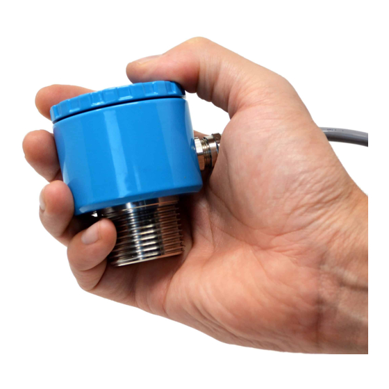
DIM 1: The fluid low level to the top of the mount, DIM 2: The gap between the mount and the bottom of the blue ULS enclosure. Go to parameter ... - Page 13 . NOTE: The reset point cannot be a higher value than the set point and have a fixed minimum hysteresis of 20 mm (0.79”). ULS Owner’s Manual Rev 0.0 Released: 12/2021...
- Page 14 NOTE: x indicates the relay number displayed. It can range from 1 to 4. Save parameters to memory EEPr To save all parameters to memory, press and hold [M] for 5 seconds. Screen will flash EEPr to indicate saving and return to Run Mode. ULS Owner’s Manual Rev 0.0 Released: 12/2021...
- Page 15 The factory set parameters are stored on temporary memory and will be lost EEPr after a power cycle. To save them to memory, press and hold [M] for 5 seconds. Screen will flash EEPr to indicate saving and return to Run Mode. ULS Owner’s Manual Rev 0.0 Released: 12/2021...
- Page 16 [rtn ] = return to previous menu. Save parameters to memory To save all parameters to memory, press and hold [M] for 5 seconds. EEPr Screen will flash EEPr to indicate saving and return to Run Mode. ULS Owner’s Manual Rev 0.0 Released: 12/2021...
- Page 17 [rtn ] = keep previous settings and return to previous menu. Save parameters to memory To save all parameters to memory, press and hold [M] for 5 seconds. EEPr Screen will flash EEPr to indicate saving and return to Run Mode. ULS Owner’s Manual Rev 0.0 Released: 12/2021...
- Page 18 [rtn ] = keep previous value and return to previous menu. Save parameters to memory To save all parameters to memory, press and hold [M] for 5 seconds. EEPr Screen will flash EEPr to indicate saving and return to Run Mode. ULS Owner’s Manual Rev 0.0 Released: 12/2021...
-
Page 19: Troubleshooting/Faq
Ensure in all operation cases that no fluid enters the deadband. If the target is far away from the unit, the problem may be that the signal is not strong enough. ULS Owner’s Manual Rev 0.0 Released: 12/2021... - Page 20 The relay chattering is likely caused by sloshing or turbulence in the target. Increasing the hysteresis between switch set point and reset point should resolve the problem, If increasing hysteresis is not possible, then increasing relay damping may resolve problem or minimize chatter. ULS Owner’s Manual Rev 0.0 Released: 12/2021...
- Page 21 12 Warranty Anfield Sensors Inc. (the “Manufacturer") warrants this product only (the "Product") to the original purchaser only (the “Purchaser”) against defective workmanship and materials under normal use of the Product for a period of twelve (12) months from the date of shipment by the Manufacturer.
Need help?
Do you have a question about the ULS and is the answer not in the manual?
Questions and answers