Table of Contents
Advertisement
Quick Links
Advertisement
Table of Contents

Summary of Contents for ICTeSecurity rf-rcvr-433
- Page 1 Wireless 433MHz Receiver Installation Manual...
- Page 2 The specifications and descriptions of products and services contained in this document were correct at the time of printing. Integrated Control Technology Limited reserves the right to change specifications or withdraw products without notice. No part of this document may be reproduced, photocopied, or transmitted in any form or by any means (electronic or mechanical), for any purpose, without the express written permission of Integrated Control Technology Limited.
-
Page 3: Table Of Contents
Contents Introduction _______________________________________________________________ 4 Mounting _________________________________________________________________ 5 Installation Wiring _________________________________________________________ 6 System Settings ___________________________________________________________ 7 4.1 Default Configuration ..................... 7 4.2 Default Operation ......................7 4.3 Custom Operation Setup ....................8 Programming Options ______________________________________________________ 9 ... -
Page 4: Introduction
Introduction The Wireless 433MHz Receiver provides a fast and simple integration of ICT 4 or 2 button remote transmitters into any alarm or access control system. The standalone functionality allows for easy, secure operation of gates or other access areas where convenience is required. The current features of the Receiver include: ... -
Page 5: Mounting
Mounting The Receiver must be mounted so that the antenna is vertical. If you are mounting the board on its side (as shown in Option 2), turn the antenna 180 degrees so it is pointing up. Option 1 Option 2 Enclosure Enclosure Wireless 433MHz Receiver... -
Page 6: Installation Wiring
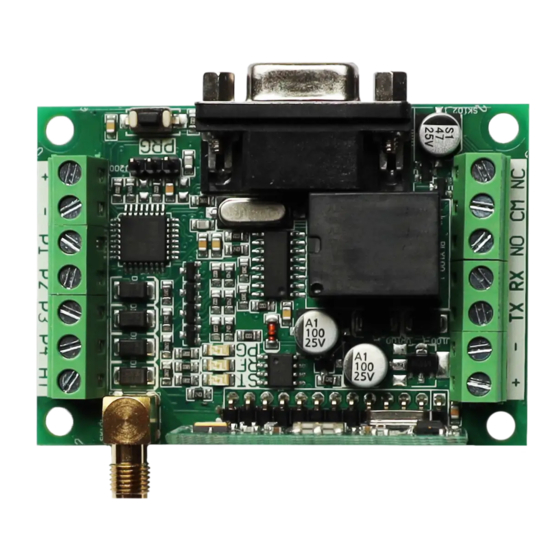
Installation Wiring Output and Antenna Connection Wiring +12V From external power supply PGM 1 Wiegand Port 1 D0 PGM 2 Wiegand Port 1 D1 PGM 3 Wiegand Port 2 D0 PGM 4 Wiegand Port 2 D1 ANTENNA Connect supplied whip wire antenna Power and Relay Output Connection Wiring RELAY NC... -
Page 7: System Settings
System Settings 4.1 Default Configuration Default Mode: ICT Pass Through RS232 Default Settings: Baud Rate 9600 Data Bits Parity None Stop Bits Flow Control None Wiegand Default Settings: Wiegand Port 1 26 Bit Unique User Wiegand Port 2 26 Bit Unique User Button Default Settings: Button 1 Wiegand Port 1... -
Page 8: Custom Operation Setup
4.3 Custom Operation Setup To customize the operation of an RF-RCVR unit to match your requirements: Connect a terminal program such as HyperTerminal with the RS232 settings shown under System Default Settings in this document. Press ESC to display the main programming menu. Wireless 433MHz Receiver | Installation Manual... -
Page 9: Programming Options
Programming Options 5.1 Mode Programming Menu Shortcut: Esc , e , Enter Type 1, Enter to toggle between the following modes: ICT Pass Through Mode (default mode) All ICT Transmitter devices will operate. Custom Site Code Mode All ICT Transmitter devices will operate with a fixed site code that is programmable in the Site Code Programming Menu. -
Page 10: Site Code Programming Menu
To Add/Modify a User: Type 1 then Enter to edit a user Type the user number then Enter Either press any button on the transmitter for this user, or type in the transmitter ID if known. To clear an entry, type 0, Enter as the TX code. -
Page 11: Button Programming Menu
5.5 Button Programming Menu Shortcut: Esc , d , Enter Type the button number and press Enter to select from: Output Wiegand data using P1 & P2 Output Wiegand data using P3 & P4 Toggle Relay or output P1/2/3/4 for 2 Seconds When used as Open collector outputs, the P1~P4 outputs will drive a 20mA load to ground. -
Page 12: Pgm Programming Menu
5.8 PGM Programming Menu Shortcut: Esc , c , Enter The L1, L2 and BZ outputs for the proximity reader device, along with 3 (P1, P2, P3) auxiliary outputs can be programmed to change state based on Wiegand data reception. Type the number corresponding to the output to be changed and press Enter, which will toggle the state between the following 3 options: ... -
Page 13: Contact
Contact Integrated Control Technology welcomes all feedback. Please visit our website (http://www.ict.co) or use the contact information below. Integrated Control Technology P.O. Box 302-340 4 John Glenn Ave North Harbour Post Centre Rosedale Auckland North Shore City 0632 New Zealand Auckland New Zealand Phone:... - Page 14 APAC Integrated Control Technology Limited 4 John Glenn Avenue, Rosedale, Auckland 0632 PO Box 302-340, North Harbour, Auckland 0751, New Zealand Email: sales@ict.co Toll Free: (0800) 428 111 Phone: 64 (9) 476 7124 AMERICAS Integrated Control Technology (USA) LLC 5265 S Rio Grande Street, Suite 201, Littleton, CO 80120 Email: ussales@ict.co Toll Free: (855) 428 9111 Phone: 720 442 0767 EMEA Integrated Control Technology (Europe) Limited...
Need help?
Do you have a question about the rf-rcvr-433 and is the answer not in the manual?
Questions and answers