Table of Contents
Advertisement
Quick Links
D
X
IGIFLE
®
RF113
SMART RF
Wireless Contact
Installation Guide
Rev1.4
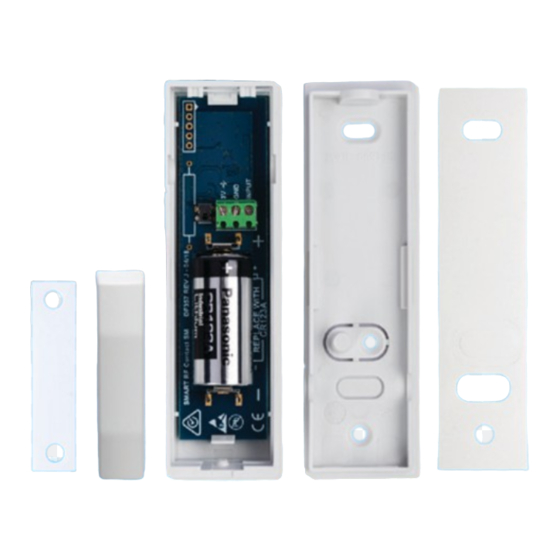
The RF113 Ships With The Following Items
RF113 Printed Wiring Assembly
RF113 Housing Including Cover And Mounting Plate
Double Sided Adhesive Tape To Suit Above Housing
Magnet Housing Including Cover And Mounting Plate
Double Sided Adhesive Tape To Suit Above Housing
Neodymium Magnet
CR123A Lithium Battery
5 x Mounting Screws and 1 x Case Lock Screw
RF113IRG Installer Reference Guide
Ensure that the transmitter is protected from
weather elements such as extreme tempera-
tures, humidity, rain or snow.
D
X
IGIFLE
P
L
TY
TD
18 Brumby Street
Seven Hills NSW 2147, AUSTRALIA
Phone:
(+612) 97417000
Email:
sales@digiflex.com.au
Web:
www.digiflex.com.au
Our Vision Is Your Peace Of Mind
29.6 mm
22.5 mm
54 mm
102 mm
17.4mm
13.5 mm
1
Opening The Housing
A
Push the screwdriver blade
3mm into the slot shown.
Do Not twist the blade!
2
Mounting
Mounting
Screw
Cable Entry
Knockout
!
Tamper
Screw
Tamper
Mounting
Screw
Case Lock Screw
Thread Length
10mm
Max
4G x10
Philips #1
B
Lift the screwdriver away
from the base to release
the cover. Do not twist or
rotate the screwdriver.
3
Battery Installation
Rear Case
Tamper
RF ID
Panasonic : CR123A
Duracell : DL123A
433.42 Mhz
Panasonic CR123A Lithium
Duracell DL123A
3.0 VDC
?
0-93% Relative Humidity
Non-condensing
For Further Information
See Your Control Panel
Functional range: -10°C to +49°C
Installation Manual
EN5013-5 Class II Only: -10°C to +40°C
C
Case Locking Screw
10mm
Max
4G x10
Philips #1
4
Wiring
Alarm
ZONE
(EOL)
Single EOL
End Of Line Resistor (EOL)
For further information refer to Control Panel EOL Selection
Wiring Distance = 8m MAX
Alarm
Tamper N/C
N/C
ZONE
(EOL)
EOL Alarm+Tamper
3V D.C. Output
Powering external devices
from this output will reduce
battery life.
N/C
Input
GND
+3V
Input
TAMPER
(EOL)
GND
+3V
Input
GND
+3V
RF113IRG Rev1.4 P/N DF2383
Advertisement
Table of Contents

Related Manuals for Digiflex RF113

Summary of Contents for Digiflex RF113
- Page 1 Installation Guide 4G x10 Rev1.4 Philips #1 Push the screwdriver blade 3mm into the slot shown. Do Not twist the blade! The RF113 Ships With The Following Items Mounting Battery Installation Wiring Alarm RF113 Printed Wiring Assembly Input Rear Case...
- Page 2 The RF113 is supplied with a double sided tape 4 Fast Flashes Device Has been Configured sible to the RF113, and align the centre of the magnet mounting option. Use this mounting method to speed Continuous Flash Device TX or RX with the alignment mark on the RF113 housing.
Need help?
Do you have a question about the RF113 and is the answer not in the manual?
Questions and answers