Advertisement
Quick Links
This product is not legal for sale or use on emission-controlled vehicles except when used as a direct
replacement part matching OEM specification.
potential ignition sources. Extinguish all open flames, prohibit smoking and
eliminate all sources of ignition in the area of the vehicle and workspace before
proceeding with the installation. Ensure you are working in a well ventilated area
with an approved fire extinguisher nearby.
Installation of this product requires modification to a fuel tank/ the fuel
system, failure to satisfy all safety considerations will result in fire, explosion,
injury and/or loss of life to yourself and/or others. All fuel system components
MUST be located as far from heat sources as possible, like exhaust, engine block,
etc.
due to incorrect maneuvering or technical errors. A falling object can cause
injury and/or loss of life to yourself and/or others. When working under the
vehicle, always use stands, and ensure that the ground or floor is stable and
level. Never crawl under a vehicle which is only supported by a jack.
pressure has been relieved. Refer to the appropriate vehicle service manual for
the procedure and precautions for relieving the fuel system pressure
appropriate safety appeal. A drilling operation will cause flying metal chips. Flying
metal chips can cause eye injury.
Installation of this product requires detailed knowledge of automotive systems
and repair procedures. We recommend that this installation be carried out by a
qualified automotive technician. Careless installation of this product can result in
damage to the product, injury or loss of life to yourself and/or others.
Always be aware of flammable situations. Drilling and grinding can be
Mechanical and hydraulic lifting devices can tip over or lower accidentally
The fuel system is under pressure. Do not open the fuel system until the
When installing this product always wear safety glasses and other
AEROMOTIVE
Part # 19105,19106,19107, and 19108
Brushless In-Tank Pump Module
2011-2017 Mustang (S197/S550)
2018-2020 Mustang GT/EcoBoost
INSTALLATION INSTRUCTIONS
WARNING!
WARNING!
WARNING!
WARNING!
CAUTION!
CAUTION:
.
Advertisement

Summary of Contents for Aeromotive 19105
- Page 1 AEROMOTIVE Part # 19105,19106,19107, and 19108 Brushless In-Tank Pump Module 2011-2017 Mustang (S197/S550) 2018-2020 Mustang GT/EcoBoost INSTALLATION INSTRUCTIONS This product is not legal for sale or use on emission-controlled vehicles except when used as a direct replacement part matching OEM specification.
- Page 2 Maximum continuous operating pressure should not exceed 70 psi. The enclosed Aeromotive fuel pump utilizes AN-08 ORB (O-ring Boss Port) style outlet port and AN-08 return port; these ports are NOT PIPE THREAD and utilize NO THREAD SEALANT.
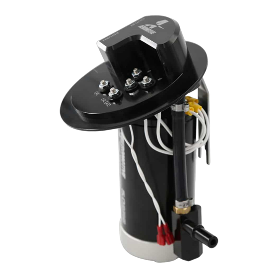
- Page 3 Outlet Port, -08 ORB Use Port Fitting, PN: 15607 Connect to 12v Positive “+” DC from Brushless Controller Return Port, -08 ORB Use Port Fitting, PN: Connect to Chassis Ground “-“ 15607 from Brushless Controller Connect to “White” or “Gray” wire from Brushless Controller (Pump Speed Signal Wire) Fuel Level Terminals...
- Page 4 6. Before removing the factory feed line, relieve system pressure (refer to service manual for proper procedure). Once system pressure has been relieved, disconnect the feed line from top plate. 7. Remove lock ring from top of tank (pump is spring loaded and will pop up when ring is removed). 8.
- Page 5 12. Once the pump body is threaded onto the -10 ORB fitting, connect the corresponding pump power, ground, and signal wires on the bottom of the outlet cap with the terminals on top of the pump body. The terminals are marked with an engraved letter on the top of the pump body and a laser mark on the top of the outlet cap.
- Page 6 13. Next, strip the two wires from the OEM fuel level sensor and crimp the two provided male quick connectors on the wires. Then install the fuel level sensor on the Aeromotive fuel level sensor bracket. To do this, slide the sensor over the bracket as shown in the below pictures, ensure the small plastic retainer clip is retained by the bracket tab.
- Page 7 14. Next, pull the jet siphon tube up out of the tank and connect it to the Aeromotive Jet Siphon male quick connect. You may have to rotate the quick disconnect on the siphon tube to get it to line up with the Aeromotive Stealth pump.
- Page 8 19. The Brushless Aeromotive fuel pump controller requires its own relay and 12V power wire along with a 0-5 volt analog input for the use of the True Variable Speed function. The use of Aeromotive fuel pump wiring kit (part # 16307) is recommended to power the A1000, Eliminator, and 3.5 remote mount brushless pump controller, use (part # 16308)
- Page 9 Air Flow from Driving When mounting the controller internally or behind obstructions in a location that will not receive much air flow from driving, mount the controller with the fins vertically as in the following image to achieve the maximum natural convective cooling.
- Page 10 MODE 1 – TPS or Other 0-5VDC Input Control Aeromotive recommends the “Mode 1” control method where the 0-5VDC signal input is tied to a Throttle Position Sensor using the output wire to the ECU. The intent for this control is to reduce the fuel pump output (and thus the amount of returned fuel flow) during low throttle opening (low engine demand) to reduce excess recycling of fuel to help keep fuel tank temperatures low.
- Page 11 30. After all wire connections are made, attach a suitable fuel pressure gauge to the fuel system Schrader valve, fuel rail or fuel pressure regulator test port. Examples: Aeromotive P/N 15632 0-15 PSI (1 ½”) Fuel Pressure Gauge Aeromotive P/N 15633 0-100 PSI (1 ½”) Fuel Pressure Gauge Ensure that any spilled fuel and any fuel-soaked shop towels are cleaned up and removed from the vicinity of the vehicle.
- Page 12 Shipping & Returns Aeromotive Inc. 11414 W 79th Street. Lenexa, KS 66214 General Inquiries and Tech Line: (913) 647-7300 General Email: info@aeromotiveinc.com Tech Email: tech@aeromotiveinc.com The Aeromotive Tech Lines are open Monday through Friday from 9:30AM to 5:00PM Central Standard Time.
- Page 13 AEROMOTIVE, INC. LIMITED WARRANTY This Aeromotive Product, with proof of purchase dated on or after January 1, 2003, is warranted to be free from defects in materials and workmanship for a period of one year from the original date of purchase.
Need help?
Do you have a question about the 19105 and is the answer not in the manual?
Questions and answers