Table of Contents
Advertisement
Quick Links
Advertisement
Table of Contents

Summary of Contents for CubeSpace CubeStar
- Page 1 CubeStar CubeSpace Star Camera User Manual...
- Page 2 Part: CubeStar Doc: User Manual Ver: Page: Document CubeStar User Manual Version Domain Public Date modified 10 December 2021 Approved by Name: Christo Groenewald...
-
Page 3: Table Of Contents
Added health check test reference images List of Figures Figure 1 – CubeStar and supplied peripherals ....................8 Figure 2 – USB-Serial Cable Connection ......................9 Figure 3 – Powered Up CubeSupport ....................... 9 Figure 4 – Connected CubeStar ........................10 Figure 5 –... - Page 4 Figure 24 – Connecting To the Development Kit ..................21 Figure 25 – Setting Debug Mode........................21 Figure 26 – Hardware Required to Program CubeStar ................22 Figure 27 – CubeStar Connected to programmer ..................22 Figure 28 – Connecting to the Target ......................23 Figure 29 –...
- Page 5 List of Tables Table 1 – CubeStar Subject Version ........................7 Table 2 – CubeStar Details ..........................28 Table 3 – CubeSupport Connects to CubeStar ..................28 Table 4 – Status and Power ..........................29 Table 5 – SRAM Test ............................29 Table 6 –...
- Page 6 Programming Header ........................19 Simplicity Commander ........................20 Installing Simplicity Commander ....................20 Programmer setup ..........................20 Programming CubeStar ........................22 Powering CubeStar whilst connected to the ADCS ............... 25 Appendix A: ..........................27 Acceptance Document ....................28 Tests Results ............................28...
-
Page 7: Table 1 - Cubestar Subject Version
Page: 1. Introduction This document will guide the user through the steps to connect CubeStar to a PC. Once a connection is established the CubeSupport ground support software can be used to interface with CubeStar. A Health Check can be performed to establish that CubeStar is working as intended. -
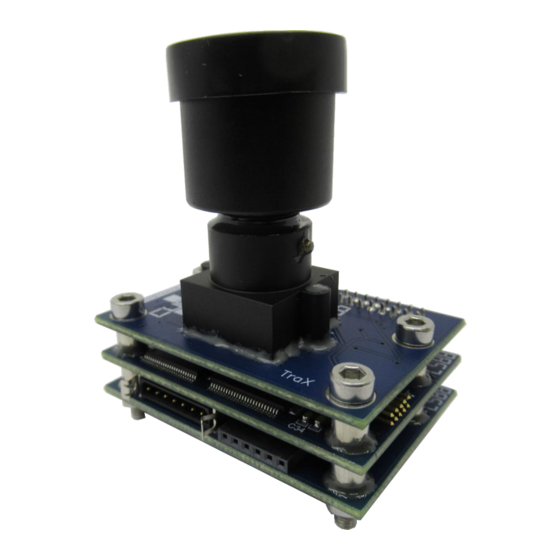
Page 8: Figure 1 - Cubestar And Supplied Peripherals
CubeStar as a standalone unit. 2.1 Hardware interface Figure 1 shows CubeStar (1) a support PCB (2), USB Serial to UART cable (3) and CubeStar interface harness (4). All these items are included in the delivered package along with a USB flash drive containing all required documentation and the CubeSupport software. -
Page 9: Figure 2 - Usb-Serial Cable Connection
Not complying with this specification can result in damaging the CubeStar electronics. Plug the UART cable into the PC used to interface with CubeStar. If the header has been plugged in with the correct orientation, the 3V3 Power On LED should light up. This is shown in Figure 3. -
Page 10: Figure 4 - Connected Cubestar
User Manual Ver: Page: Figure 4 – Connected CubeStar 2.2 Com Port Setup The COM port should register on the PC once the USB cable is connected to the PC and the drivers have been installed. To check if the COM port is registered by the PC open the Device Manager. -
Page 11: Figure 6 - Usb Serial Port Settings
Figure 7 – USB serial port advanced settings 2.3 CubeSupport Interface Once the steps in the previous section have been completed the CubeSupport software that can be found on the included USB drive can be used to connect to CubeStar. -
Page 12: Figure 8 - Add A Connection To Cubesupport
CubeStar interface should show up as described in the following section. 2.4 User-Interface The user interface is shown in Figure 10. The interface consists of two tabs 1. The CubeStar tab: A wrapper for all available telemetries and telecommands. 2. The CubeStar- Images tab: A utility to download images. -
Page 13: Figure 10 - Cubestar Ui
Throughout this interface, telecommands can be sent with transmit ( ) buttons and telemetry requests can be made with refresh ( ) buttons. For a more in-depth description of the available telemetries and telecommands, refer to the “CubeStar Interface Control Document”, and “CubeStar Reference Manual”. -
Page 14: Figure 11 - Cubestar Status Panel
3. Health Check This section provides the steps required to perform a “bench-test” on CubeStar to determine if it is working as it should. This section is only applicable to clients who bought CubeStar as a standalone unit. The CubeStar can be tested with the lens cap on the lens or without the lens cap. -
Page 15: Figure 14 - Cubestar Test Panel
Note all of the values in Table 4. • 3.2 Performing an SRAM test Navigate to the CubeStar → CubeStar - Test tab as shown in Figure 14. Figure 14 – CubeStar Test Panel Click on the green arrow( ) next to the Test SRAM telecommand and wait for roughly •... -
Page 16: Figure 16 - Setting The Image Sensor Exposure
Figure 16 – Setting the Image Sensor Exposure Remove the star tracker lens cap; • Navigate to the CubeStar → CubeStar → Capture Image tab, and capture an image. • Figure 17 – Capturing an Image Navigate to the CubeStar – Images tab and download the image •... -
Page 17: Figure 19 - Example Cubestar Image
Note a successful image capture in Table 7 in the acceptance test document. • 3.5 Capture Test Image Navigate to the CubeStar – Test tab and select the Fixed test pattern as shown in Figure • 20. Transmit the command by using the green arrow ( Figure 20 –... -
Page 18: Figure 21 - Cubestar Fixed Test Image
Part: CubeStar Doc: User Manual Ver: Page: Figure 21 – CubeStar Fixed Test Image... -
Page 19: Figure 22 - Cubestar Programming Header
Ver: Page: 4. Updating CubeStar In the case that CubeSpace provides new firmware files that can be flashed to CubeStar, the steps in this section can be followed to program CubeStar. 4.1 Programming Header The programming header can be found next to the interface header on the bottom PCB of CubeStar. -
Page 20: Figure 23 - Simplicity Commander Home View
Silicon Labs offers a software package called Simplicity Commander. This allows the required functionality to upload a new binary to the CubeStar star tracker. This section will guide you through the process of setting up Simplicity Commander to flash a new binary to CubeStar. -
Page 21: Figure 24 - Connecting To The Development Kit
Part: CubeStar Doc: User Manual Ver: Page: Notice that the starter kit can be selected under the “J-Link device” dropdown menu, as shown below. Make sure that the starter kit has been connected. Select the kit and set it as active by click on the “Connect”... -
Page 22: Figure 26 - Hardware Required To Program Cubestar
Your starter kit should now be ready to program an external target. 4.5 Programming CubeStar The CubeStar firmware can be updated using a Silicon Labs EFM32 Giant Gecko Starter Kit and the provided cables. The required starter kit and cables are shown below. -
Page 23: Figure 28 - Connecting To The Target
Ver: Page: Ensure that the starter kit is detected by Simplicity Commander Once CubeStar has been powered up and connected to the programmer, click on the “Connect” button. Figure 28 – Connecting to the Target The device type should automatically be detected. When navigating to the “Device Info” tab,... -
Page 24: Figure 29 - The Device Info Tab
Part: CubeStar Doc: User Manual Ver: Page: Figure 29 – The Device Info Tab To flash the chip, navigate to the “Flash” tab. The Flash Programmer window will open. Figure 30 – Flashing the Hardware Set all options as shown in Figure 30. -
Page 25: Figure 31 - Enabling Adcs Run Mode
CubeStar. 4.6 Powering CubeStar whilst connected to the ADCS It is possible to reprogram CubeStar while it is connected to the ADCS. To be able to power CubeStar during this configuration, the following steps should be followed: Turn on the ADCS power •... -
Page 26: Figure 32 - Powering On Cubestar
ADCS→Adcs 3-Axis→ADCS Run Mode tab and selecting AdcsOff, as shown in Figure 33. Figure 33 – Disabling ADCS Run Mode The CubeStar unit should now be powered on, and ready to be reprogrammed by following the steps in Section 4.5. - Page 27 Part: CubeStar Doc: User Manual Ver: Page: Appendix A:...
-
Page 28: Table 2 - Cubestar Details
CubeSupport application connects to the CubeStar as it should and check each step in Table 3. The CubeStar can be tested with the lens cap on the lens or without the lens cap. The values marked with (value)C shows the values expected with a lens cap, and values marked with (value)NC shows values expected without a lens cap. -
Page 29: Table 4 - Status And Power
AVG Current 30 ±3 mA Table 5 – SRAM Test Test / Task Expected Result Result CubeStar → CubeStar - Test → Current ADCS State Test Passed (1) SRAM Test Results Table 6 – Operations Test / Task Expected Result Result CubeStar →... - Page 30 CubeStar Timing → Timing Summary → 680 ± 20 ms Capture >250 ms Detection < 10 ms Identification CubeStar CubeStar Best Star → Star vectors → All Zeros Star 1 Vectors All Zeros Star 2 Vector All Zeros Star 3 Vectors CubeStar CubeStar Attitude →...
-
Page 31: Table 7 - Image Downloaded
Test Pattern was successfully captured and downloaded Test pattern Captured and looks like the example Please complete the preceding acceptance test and return a digital copy of it to CubeSpace along with copies of the captured image and test pattern...
Need help?
Do you have a question about the CubeStar and is the answer not in the manual?
Questions and answers