
Subscribe to Our Youtube Channel
Summary of Contents for CLAUSING MS1318M
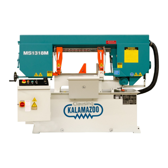
- Page 1 MS1318M Manual Miter Bandsaw MS1318SA Semi-Automatic Miter Bandsaw Instruction Manual Version 7 20210315 Clausing Industrial, Inc.
- Page 3 MS1318M / MS1318SA Safety rules ƒ It’s essential to power on your bandsaw machine for at least one hour every two years, if you seldomly use the machine. (This period of power-on must be without proceeding with other operation) Otherwise the machine program may disappear due to not strictly follow this safety rule.
- Page 4 MS1318M / MS1318SA Safety rules ƒ Never cut carbon or any other material that may produce and disperse explosive dust. It is possible that sparks from motors and other machine parts will ignite and explode the air-borne dust. ƒ Never adjust the wire brush or remove chips while the saw blade is still running.
-
Page 5: Table Of Contents
Anchoring the machine ………………………………………………………………………………….. 3-9 Installing Roller Table ………………………………………………….…………………………………. 3-9 Installing Fire Control Device ………………………………………………….……………………… 3-9 Relocating ………………………...…………………………………………………………………….…………………. 3-9 Operating Instructions Section 4 – Safety Precautions …………………..…………………..……………………………………….……………………. 4-2 Before Operating …………………………..……………………………………………………………………………. 4-3 Control Panel (MS1318M) ……..………………..………………………………………….……………………… 4-4 Control Panel ………………….………………………………………………………………………..……. 4-4... - Page 6 MS1318M / MS1318SA Table of Contents Control Buttons ……………………………………………………………………………………….…….. 4-4 Control Panel (MS1318SA) ……..………………..……………………………………….……………………… 4-5 Control Panel ………………….………………………………………………………………………..……. 4-5 Control Buttons ……………………………………………………………………………………….…….. 4-5 Standard Accessories ………….………………………..……………………………………………….…………… 4-7 Unrolling & Installing the Blade …………..………..……………………………………………………………. 4-9 Adjusting Blade Speed ………..………..……………………………………………………………………………. 4-10 Adjusting Saw Arm ………..………..…………………………………………………………………………………. 4-11 Adjusting Coolant Flow ………..………..…………………………………………………………………..……….
- Page 7 MS1318M / MS1318SA Table of Contents Troubleshooting Section 9 – Introduction ……………………….…….…………………..……………………………………………………………. 9-1 Precautions ………………….…………………..……………………………………………………………………..9-2 General Troubles & Solutions ………………………..……………………………………………………………. 9-2 Minor Troubles & Solutions ………………………..………………………………………………..……………. 9-3 Motor Troubles & Solutions ………………………..…………………………………………………..…………. 9-3 Blade Troubles & Solutions ………………………..……………………………………………………………….. 9-4 Sawing Problems &...
- Page 8 MS1318M / MS1318SA...
-
Page 9: Safety Information
MS1318M / MS1318SA Section 1 SAFETY INFORMATION SAFETY INSTRUCTIONS SAFEGUARD DEVICES EMERGENCY STOP SAFETY LABELS HEARING PROTECTION CE COMPLIANCE RISK ASSESSMENT Safety is a combination of a well-designed machine, operator’s knowledge about the machine and alertness at all times. Our band machine has incorporated many safety measures during the design process and used protective devices to prevent personal injuries and potential risks. - Page 10 MS1318M / MS1318SA This manual has important safety Wear proper apparel during operation information. Read through it carefully and when servicing the machine. Some before operating this machine to personal protective equipment is prevent personal injury or machine required for the safe use of the machine, damage.
- Page 11 MS1318M / MS1318SA MS1318M / MS1318SA SAFEGUARD DEVICES The safeguard devices incorporated in this machine include the following two main parts: 1. Protection covers & guards 2. Safety-related switches Protection Covers & Guards 1. Idle wheel housing cover 2. Drive wheel housing cover 3.
- Page 12 MS1318M / MS1318SA Safety Related Switches To protect the operator, the following safety related switches on the machine are actuated when the machine is in operation. Wheel motion detector This is a proximity sensor used to detect the motion of the drive wheel. Once the saw blade is broken...
-
Page 13: Emergency Stop
MS1318M / MS1318SA MS1318M / MS1318SA Illustration: Emergency Stop Emergency Stop MS1318M Emergency Stop MS1318SA... -
Page 14: Safety Labels
MS1318M / MS1318SA SAFETY LABELS Please read through and understand these safety labels before operating the machine. Refer to Illustration: Safety Labels. Label Meaning Label Meaning Impact Hazard Read Operator’s Manual WEAR SAFETY SHOES. Do This manual has important safety not approach dropping area information. -
Page 15: Illustration: Safety Labels
MS1318M / MS1318SA MS1318M / MS1318SA Illustration: Safety Labels MS1318M/SA... -
Page 16: Hearing Protection
MS1318M / MS1318SA HEARING PROTECTION Always use ear protection! When your machine is running, noise generated by the machine may come from the following: Saw blade during cutting or material feed mechanism Wire brush unit Chip conveyor unit Speed reducer... -
Page 17: General Information
MS1318M / MS1318SA Section 2 GENERAL INFORMATION SPECIFICATION MACHINE PARTS IDENTIFICATION FLOOR PLAN This band saw machine is designed by our R&D engineers to provide you the following features and advantages: Safety This machine is designed to fully protect the operator from its moving parts during cutting operation. - Page 18 0 mm Clamping Clamping Pressure ------------------------------- 32.3” (820 mm) Workbed Height MS1318M: 1,320 lb (600 kg) MS1318SA: 1,408 lb (640 kg) Weight MS1318M: 1,760 lb (800 kg) Gross MS1318SA: 1,848 lb (840 kg) MS1318M : 84.7” x 51.93” x 57.8” (2,152 x 1,319 x 1,469 mm)
- Page 19 MS1318M / MS1318SA MS1318M Saw Bow Left Guide Arm Slide Plate Right Guide Arm Idle Wheel Cover Blade Motor Control Panel Pulley Cover Drive Wheel Electrical Compartment Cover Work Bed Base Rotating Pivot Seat MS1318SA Saw Bow Left Guide Arm...
-
Page 20: Floor Plan
MS1318M / MS1318SA FLOOR PLAN MS1318M Machine top view Machine front view... - Page 21 MS1318M / MS1318SA Machine side view...
- Page 22 MS1318M / MS1318SA MS1318SA Machine top view Machine front view...
- Page 23 MS1318M / MS1318SA Machine side view...
- Page 24 MS1318M / MS1318SA...
-
Page 25: Moving & Installation
MS1318M / MS1318SA Section 3 MOVING & INSTALLATION LOCATION & ENVIRONMENT UNPACKING & INSPECTING LIFTING REMOVING SHIPPING BRACKET CLEANING INSTALLING RELOCATING LOCATION & ENVIRONMENT For your safety, please read all information regarding installation before proceeding. Install your machine in a place satisfying all of the following conditions:... -
Page 26: Unpacking & Inspecting
MS1318M / MS1318SA UNPACKING & INSPECTING Unpack your machine carefully to avoid damage to machine parts or surfaces. Upon arrival of your new band saw, please confirm that your machine is the correct model and it comes in the same specification you ordered by checking the model plate on the machine base. -
Page 27: Lifting
MS1318M / MS1318SA LIFTING When moving the machine, we strongly suggest you choose any one of the methods described below to move your machine. (Only applies to the machine with the design of the hanging point.) Move the machine to its location by using a crane and a wire rope sling that can fully withstand the weight of the machine (refer to machine specification under Section 2 General Information). - Page 28 MS1318M / MS1318SA When you work together with more than two people, it is best to keep constant verbal communication with each other. Use a forklift (Only applies to the machine with the design of the lifting point.) Make sure that the lifting rod can fully withstand the weight of the machine. (Refer to Section 2 –...
-
Page 29: Illustration: Lifting Points
MS1318M / MS1318SA 3. Use rolling cylinders You can use rolling cylinders to move your machine in a small machine shop environment. You must use rolling cylinders made in material of proper compressive strength. 4. Other ways to move If the machine does not have stickers, please contact your local agent immediately. -
Page 30: Removing Shipping Bracket
MS1318M / MS1318SA REMOVING SHIPPING BRACKET After the machine has been properly positioned, remove the shipping bracket that is used to lock the saw frame and the saw bed. Retain this bracket so that it can be used again in the event that your machine must be relocated. -
Page 31: Supplying Coolant
MS1318M / MS1318SA Supplying coolant Fill the coolant tank to the middle level of the sight gauge by pouring the coolant from above the chip conveyor. Use the sight gauge to check the coolant level remaining in the tank. Always check the coolant supply before starting the machine. -
Page 32: Leveling
MS1318M / MS1318SA Turn off the shop circuit breaker. Make sure the machine circuit breaker switch on the electrical compartment door is turned to OFF. Remove the screw securing the electrical compartment and then open the door. Pull the power supply cable and grounding conductor through the power supply inlet into the electrical compartment. -
Page 33: Anchoring The Machine
MS1318M / MS1318SA Anchoring the machine Normally there is no need to anchor the machine. If the machine is likely to vibrate, fix the machine to the floor with anchor bolts. Shock absorption steel plates are provided and can be placed under each leveling bolt to prevent their sinking into the concrete floor. - Page 34 MS1318M / MS1318SA...
-
Page 35: Operating Instructions
MS1318M / MS1318SA Section 4 OPERATING INSTRUCTION SAFETY PRECAUTIONS BEFORE OPERATING CONTROL PANEL STANDARD ACCESSORIES UNROLLING & INSTALLING THE BLADE ADJUSTING BLADE SPEED ADJUSTING SAW ARM ADJUSTING COOLANT FLOW INSTALLING MATERIAL STOP BRACKET ADJUSTING WIRE BRUSH TEST-RUNNING THE MACHINE BREAKING-IN THE BLADE... - Page 36 MS1318M / MS1318SA SAFETY PRECAUTIONS For your safety, please read and understand the instruction manual before you operate the machine. The operator should always follow these safety guidelines: The machine should only be used for its designated purpose. Do not wear gloves, neckties, jewelry or loose clothing/hair while operating the machine.
-
Page 37: Before Operating
MS1318M / MS1318SA BEFORE OPERATING Choosing an appropriate saw blade and using the right cutting method is essential to your cutting efficiency and safety. Select a suitable saw blade and cutting method based on your work material and job requirements e.g. cutting accuracy, cutting speed, economic concern, and safety control. -
Page 38: Control Panel (Ms1318M)
MS1318M / MS1318SA CONTROL PANEL (MS1318M) The control panel is located on the top of the electrical box. It includes the following function: power system, hydraulic system, cooling system and the light system. The operator must fully understand the function of each switch and button before operating the machine. - Page 39 MS1318M / MS1318SA *Optional Saw Blade Safety button For safety purpose, to start saw blade, the operator has to press saw blade start button and *saw blade safety button simultaneously. The saw blade safety button is on the right side of control box as shown below.
-
Page 40: Control Panel (Ms1318Sa)
MS1318M / MS1318SA CONTROL PANEL (MS1318SA) Name Name Vise clamp/open switch 6 Saw bow down button Coolant pump ON/OFF switch 7 Saw bow quick approach button Saw blade start button 8 Emergency stop button Saw blade stop button 9 Power indicator lamp... - Page 41 MS1318M / MS1318SA *Optional Saw Blade Safety button For safety purpose, to start saw blade, the operator has to press saw blade start button and *saw blade safety button simultaneously. The saw blade safety button is on the right side of control box as shown below.
-
Page 42: Standard Accessories
MS1318M / MS1318SA Before descending the saw bow, please move the guide arm to a safe position to prevent it from hitting the vise. 8. Emergency stop button Press this button to stop the machine in an emergency. When the button is pressed, it brings the machine to a full stop. - Page 43 MS1318M / MS1318SA Gear reducer The specially designed gear reducer can work toward your preset blade speed and torque. Please refer to section 8 for information on maintenance. Saw bow swivel lock handle This lock handle is used to lock the saw bow when it is settled at the designated angle before miter cutting.
-
Page 44: Unrolling & Installing The Blade
MS1318M / MS1318SA 0.5M Roller Table (standard for MS1318SA) This 0.5M roller table supports the work material and ensures the material is fed in smoothly. UNROLLING & INSTALLING THE BLADE Always wear leather gloves and protection glasses when handling a blade. - Page 45 MS1318M / MS1318SA Step 3 - Press the saw bow up button and elevate the saw bow to the highest position. Step 4 - Release blade tension by turning the blade tension handle counterclockwise. The idle wheel will then move slightly toward the direction of the drive wheel.
-
Page 46: Adjusting Blade Speed
MS1318M / MS1318SA ADJUSTING BLADE SPEED Step 1 – Set the blade speed control knob to “0” position. Step 2 – Press the saw blade start button to start the blade. Step 3 – Refer to blade speed reference chart and turn the blade speed control knob to adjust the blade speed. -
Page 47: Adjusting Coolant Flow
MS1318M / MS1318SA ADJUSTING COOLANT FLOW Step 1 – Press the saw blade start button to start the saw blade drive motor. Step 2 – Use the flow control valve (shown below) to adjust the amount of fluid flowing to the cutting area. -
Page 48: Adjusting Wire Brush
MS1318M / MS1318SA ADJUSTING WIRE BRUSH Follow these steps to adjust wire brush to appropriate position: Step 1 – Open the drive wheel cover. Loosen the adjustment bolt. Step 2 – Adjust brush to make it move up / down until it makes proper contact with the saw blade (see below illustration). -
Page 49: Breaking-In The Blade
Step 8 – Select the proper cutting condition according to different material. Step 9 – After the entire cutting job is completed, MS1318M will stay at lower limit position and MS1318SA will go up to the upper limit position. Open the vises to remove the workpiece. - Page 50 MS1318M / MS1318SA USING TOP CLAMP FOR BUNDLE CUTTING (Optional) Before Cutting , Make sure that the bundle is properly tightly clamped but not being distorted by clamp force. Any improper bundle cutting can cause damage to the blade, reduce the blade life.
-
Page 51: Terminating A Cutting Operation
Step 3 – Remove the stud bolts. TERMINATING A CUTTING OPERATION For MS1318M, the saw blade will stop running when the emergency stop button is pressed. For MS1318SA, the saw blade will stop running when the saw bow up button or the saw blade stop button is pressed. - Page 52 MS1318M / MS1318SA...
-
Page 53: Electrical System
MS1318M / MS1318SA Section 5 ELECTRICAL SYSTEM ELECTRICAL CIRCUIT DIAGRAMS The following are electrical circuit diagrams of MS1318M: Fig 5-1 Control Panel Layout Fig 5-2 AC 110V Circuitry Fig 5-3 Power Supply Layout The following are electrical circuit diagrams of MS1318SA:... - Page 54 MS1318M / MS1318SA Fig 5-1 Control Panel Layout...
- Page 55 MS1318M / MS1318SA Fig 5-2 AC 110V Circuitry...
- Page 56 MS1318M / MS1318SA Fig 5-3 Power Supply Layout...
- Page 57 MS1318M / MS1318SA Fig 5-4 Control Panel Layout...
- Page 58 MS1318M / MS1318SA Fig 5-5 AC 110V Circuitry...
- Page 59 MS1318M / MS1318SA Fig 5-6 Power Supply Layout...
- Page 60 MS1318M / MS1318SA...
-
Page 61: Hydraulic System
MS1318M / MS1318SA Section 6 HYDRAULIC SYSTEM HYDRAULIC DIAGRAMS... - Page 62 MS1318M / MS1318SA MS1318SA...
- Page 63 MS1318M / MS1318SA...
- Page 64 MS1318M / MS1318SA...
- Page 65 MS1318M / MS1318SA...
- Page 66 MS1318M / MS1318SA...
- Page 67 MS1318M / MS1318SA...
- Page 68 MS1318M / MS1318SA...
- Page 69 MS1318M / MS1318SA...
- Page 70 MS1318M / MS1318SA...
- Page 71 MS1318M / MS1318SA...
- Page 72 MS1318M / MS1318SA...
-
Page 73: Bandsaw Cutting: A Practical Guide
MS1318M / MS1318SA Section 7 BANDSAW CUTTING: A PRACTICAL GUIDE INTRODUCTION SAW BLADE SELECTION VISE LOADING BLADEBREAK-IN... - Page 74 MS1318M / MS1318SA INTRODUCTION Constant Variable Min. SAW BLADE SELECTION 1. Band length The dimensions of the band will depend on the band saw machine that has been installed. Please refer to Section 2 – General Information 2. Band width Band width: the wider the band saw blade, the more stability it will have.
-
Page 75: Vise Loading
MS1318M / MS1318SA 4. Tooth pitch The main factor here is the contact length of the blade in the workpiece. If it is 4P, 25.4 ÷ 4 P = 6.35 mm, that is, one tooth is 6.35 mm. If it is 3P, 25.4 ÷ 3 P = 8.46 mm If the number is small, it means that the tooth is large. -
Page 76: Bladebreak -In
MS1318M / MS1318SA BladeBreak -In... -
Page 77: Maintenance & Service
MS1318M / MS1318SA Section 8 MAINTENANCE & SERVICE INTRODUCTION BASIC MAINTENANCE MAINTENANCE SCHEDULE BEFORE BEGINNING A DAY’S WORK AFTER ENDING A DAY’S WORK Every 2 weeks First 600hrs for new machine,then every 1200hrs for routine change EVERY SIX MONTHS STORAGE CONDITIONS... - Page 78 MS1318M / MS1318SA MAINTENANCE SCHEDULE We suggest you do the maintenance on schedule. Before beginning a day’s work 1. Please check the hydraulic oil level. If oil level volume is below 1/2, please add oil as necessary.(Filling up to 2/3 level is better for system operation.) 2.
- Page 79 MS1318M / MS1318SA Grease Injection Hole: Grease Injection Nozzles at the middle of drive wheel and idle wheel; (You need to rotate the wheel until you ssee the Grease injection nozzle.) : The position of injection indicating. Please inject the grease into the Nozzle.
- Page 80 MS1318M / MS1318SA Manual Lubrication Injection Device: Lubrication volume indicator. Recommend keeping the volume over 50% inside the vessel. Please take down this vessel cap to replenish the lubrication. For the prevention of working environment pollution, DO NOT replenish too much volume of lubrication while supplying the lubrication into the vessel.
- Page 81 MS1318M / MS1318SA Gear Oil & Grease Injection Hole 1. A grease injection hole and a gear oil injection hole on the top of gear reducer. : The position of injection indicating. Gear Oil Injection Hole Recommend keeping the volume under 50% inside the vessel of volume window.
- Page 82 MS1318M / MS1318SA TERMINATING THE USE OF THE MACHINE Waste disposal: When your machine can not work anymore, you should drain the oil from machine body. Please store the oil in safe place with bottom tray. Ask a environment specialist to handle the oil. It can avoid soil pollution.
-
Page 83: Precautions
MS1318M / MS1318SA Section 9 TROUBLESHOOTING INTRODUCTION PRECAUTIONS GENERAL TROUBLES & SOLUTIONS MINOR TROUBLES & SOLUTIONS MOTOR TROUBLES & SOLUTIONS BLADE TROUBLES & SOLUTIONS SAWING PROBLEMS & SOLUTIONS RE-ADJUSTING THE ROLLER TABLE INTRODUCTION All the machines manufactured by us pass a 48 hours continuously running test before shipping out and we are responsible for the after sales service problems during the warranty period if the machines are used normally. - Page 84 MS1318M / MS1318SA PRECAUTIONS When an abnormality occurs in the machine during operation, you can do it yourself safely. If you have to stop machine motion immediately for parts exchanging, you should do so according to the following procedures: Press HYDRAULIC MOTOR OFF button or EMERGENCY STOP button.
-
Page 85: Minor Troubles & Solutions
MS1318M / MS1318SA MINOR TROUBLES & SOLUTIONS TROUBLE PROBABLE CAUSE SUGGESTED REMEDY Saw blade motor does not run Overload relay activated Reset even though blade drive button Saw blade is not at forward Press SAW FRAME is pressed. limit position. - Page 86 MS1318M / MS1318SA BLADE TROUBLES AND SOLUTIONS DISCONNECT POWER CORD TO MOTOR BEFORE ATTEMPTING ANY REPAIR OR INSPECTION. TROUBLE PROBABLE CAUSE SUGGESTED REMEDY Too few teeth per inch Use finer tooth blade Loading of gullets Use coarse tooth blade or cutting lubricant.
- Page 87 MS1318M / MS1318SA SAWING PROBLEMS AND SOLUTIONS Other than this manual, the manufacturer also provides some related technical documents listed as follows: Sawing Problems and Solutions Vibration during cutting Failure to cut Short life of saw blade Curved cutting Broken blade...
- Page 88 MS1318M / MS1318SA Probable Cause : A. Improper break-in procedure. B. Excessive band speed for the type of material being cut. This generates a high tooth tip temperature resulting in accelerated tooth wear. C. Low feed rate causes teeth to rub instead of penetrate.
- Page 89 MS1318M / MS1318SA Probable Cause : A. Broken, worn or missing back-up guides allowing teeth to contact side guides. B. Improper side guides for band width. C. Backing the band out of an incomplete cut. Probable Cause : A. Worn wheel flange, allowing side of teeth to contact wheel surface or improper tracking on flangeless wheel.
- Page 90 MS1318M / MS1318SA #5. Body Breakage Or Cracks From Back Edge Probable Cause : A. Excessive back-up guide "preload" will cause back edge to work harden which results in cracking. B. Excessive feed rate. C. Improper band tracking back edge rubbing heavy on wheel flange.
- Page 91 MS1318M / MS1318SA Probable Cause : A. Too fine of a tooth pitch insufficient gullet capacity. B. Excessive feeding rate producing too large of a chip. C. Worn, missing or improperly positioned chip brush. D. Insufficient sawing fluid due to inadequate supply, improper ratio and/or improper application.
- Page 92 MS1318M / MS1318SA Probable Cause : A. Excessive feed rate. B. Excessive back-up guide "preload". C. Improper band tracking back edge rubbing heavy on wheel flange. D. Worn or defective back-up guides. Probable Cause : A. Any of the factors that cause body breaks can also cause butt weld breaks.
- Page 93 MS1318M / MS1318SA Probable Cause : A. Excessive back-up guide "preload". B. Improper band tension. C. Guide arms spread to maximum capacity. D. Improper beam bar alignment. E. Side guide adjustment is too tight. F. Excessively worn teeth. Probable Cause : A.
-
Page 94: Re-Adjusting The Roller Table
MS1318M / MS1318SA Probable Cause : A. Excessive band tension B. Any of the band conditions which cause the band to be long (#18) or short (#19) on tooth edge. C. Cutting a tight radius. RE-ADJUSTING THE ROLLER TABLE If the feeding table suffers the huge stroke and the alignment is effected, follow the below procedure to adjust. -
Page 95: Parts
MS1318M / MS1318SA Section 10 PARTS SPARE PARTS RECOMMENDATIONS PART LIST SPARE PARTS RECOMMENDATIONS The following table lists the common spare parts we suggest you purchase in advance: Part Name Part Name Saw blade Coolant tank filter Wire brush Steel plates... - Page 96 MS1318M / MS1318SA 10-2...
- Page 97 MS1318M / MS1318SA 10-3...
- Page 98 MS1318M / MS1318SA 10-4...
- Page 99 MS1318M / MS1318SA 10-5...
- Page 100 MS1318M / MS1318SA 10-6...
- Page 101 MS1318M / MS1318SA 10-7...
- Page 102 MS1318M / MS1318SA 10-8...
- Page 103 MS1318M / MS1318SA 10-9...
- Page 104 MS1318M / MS1318SA 10-10...
- Page 105 MS1318M / MS1318SA 10-11...
- Page 106 MS1318M / MS1318SA 10-12...
- Page 107 MS1318M / MS1318SA 10-13...
- Page 108 MS1318M / MS1318SA 10-14...
- Page 109 MS1318M / MS1318SA 10-15...
- Page 110 MS1318M / MS1318SA 10-16...
- Page 111 MS1318M / MS1318SA 10-17...
- Page 112 MS1318M / MS1318SA 10-18...
- Page 113 MS1318M / MS1318SA 10-19...
- Page 114 MS1318M / MS1318SA 10-20...
- Page 115 MS1318M / MS1318SA 10-21...
- Page 116 MS1318M / MS1318SA 10-22...
- Page 117 MS1318M / MS1318SA 10-23...
- Page 118 MS1318M / MS1318SA 10-24...
- Page 119 MS1318M / MS1318SA 10-25...
- Page 120 MS1318M / MS1318SA 10-26...
- Page 121 MS1318M / MS1318SA 10-27...
- Page 122 MS1318M / MS1318SA 10-28...
- Page 123 MS1318M / MS1318SA 10-29...
- Page 124 MS1318M / MS1318SA 10-30...
- Page 125 MS1318M / MS1318SA 10-31...
- Page 126 MS1318M / MS1318SA 10-32...
- Page 127 MS1318M / MS1318SA 10-33...
- Page 128 MS1318M / MS1318SA 10-34...
- Page 129 MS1318M / MS1318SA 10-35...
- Page 130 MS1318M / MS1318SA 10-36...
- Page 131 MS1318M / MS1318SA 10-37...
- Page 132 MS1318M / MS1318SA...
- Page 133 MS1318M / MS1318SA...
- Page 134 MS1318M / MS1318SA...
Need help?
Do you have a question about the MS1318M and is the answer not in the manual?
Questions and answers