Table of Contents
Advertisement
Quick Links
OPERATION
MANUAL
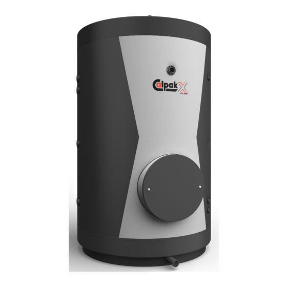
Ultratank Calpak X-FLOW
Δt = 1
The technology we have developed permits the
transmission of water from the tank to the
stainless hot water exchanger, with a temperature
difference of only 1 degree. This means rapid
achievement of the desirable temperature and a
steady flow of hot water for consumption.
www.calpak.gr
= 99%
η
th
The Calpak X-FLOW tank produces the hot water
that you need, with a 99% efficiency rate. This
means that the energy source is fully used, thus
saving you a lot of money.
ΕPO PATENTED
TECHNOLOGY
LAB MEASUREMENTS
FOR EFFICIENCY BY
"DEMOKRITOS"
Advertisement
Table of Contents

Related Manuals for CALPAK X-FLOW


Summary of Contents for CALPAK X-FLOW
- Page 1 η Δt = 1 The technology we have developed permits the The Calpak X-FLOW tank produces the hot water transmission of water from the tank to the that you need, with a 99% efficiency rate. This stainless hot water exchanger, with a temperature means that the energy source is fully used, thus difference of only 1 degree.
- Page 3 Ultratank CALPAK X-FLOW Dear Customer, Thank you for your preference for our products. Its leading technology, in conjunction with its functionality and reliability, makes it the most efficient solution for hot water management. The product comprises the following main components: •...
-
Page 5: Table Of Contents
CIRCULATOR CONFIGURATION AND INSTALLATION OF 1.5 m³/H CALPAK X-FLOW COUNTERFLOW KIT (FOR 500 LT, 1000 LT AND 2000 LT TANKS) 3.3.3. CIRCULATOR CONFIGURATION AND INSTALLATION OF 3.0 & 4.5 m³/H CALPAK X-FLOW COUNTERFLOW KIT (FOR 1000 LT TANKS) 3.3.4. CIRCULATOR CONFIGURATION AND INSTALLATION OF 3.0 & 4.5 m³/H CALPAK X-FLOW COUNTERFLOW KIT (FOR 2000 LT TANKS) 3.3.5... -
Page 6: Guarantees & Compliance
GUARANTEES & COMPLIANCE The guarantee begins when the product is installed at the location of the final user. The legal sale document or receipt will be proof of the installation date. Our company guarantees the excellent quality of the materials and the sound manufacture of the product. -
Page 7: Circulation Pump
CIRCULATION PUMP The circulation pump comes with a 2-year guarantee. CONTROL UNIT The control unit comes with a 2-year guarantee. CE DECLARATION OF CONFORMITY (in accordance with Directives 2004/108/EC and 2006/95/EC) This Declaration certifies that the product complies with the requirements of Directives 2004/108/EC and 2006/95/EC (Directive on electromagnetic compatibility and Directive on the harmonisation of the laws of Member States relating to electrical equipment designed for use within certain voltage limits), and certifies that the information included in the product’s technical file are true. - Page 8 DATE OF PURCHASE: DATE OF INSTALLATION: TYPE: CFA/3 CFA/3xxxxx Un 230 V In 20 mA 50 Hz IP 20 FOR INTERNAL INSTALLATION AND USE (on the front of the device) The device must not be used next to or mounted on top of other devices. If it is necessary to use the device next to or on top of other equipment, the device must be checked to verify that it functions properly in such configuration.
-
Page 9: Instructions For Safe Operation - Proper Use
2 INSTRUCTIONS FOR SAFE OPERATION - PROPER USE IN GENERAL In this manual, you will find safety instructions which you must follow to ensure your own safety and to protect the product and the equipment connected to it. The instructions are accompanied by a warning triangle and, depending on the level of risk, they are divided into the following categories. -
Page 10: Instructions For Safe Operation
INSTRUCTIONS FOR SAFE OPERATION • The installation, connection and initial start-up should only be undertaken by authorised and trained installers. • Disconnect the power supply before you start doing any work on the device. • Make sure that all the safety valves comply with the requirements of standard EN 12828 for connection with the heating side and standard EN 12897 for the water side. -
Page 11: Product Description
3 PRODUCT DESCRIPTION DEFINITION FOR ULTRATANK “A tank through which hot water passes, with the possibility of connection to multiple charging sources. Its exceptional property is the ability to provide a large and stable flow of hot water, after being charged at a temperature exceeding the desired hot water temperature by only one degree, thus resulting in a more economical operation of power sources (heat pump, boiler, solar panels, etc.) and exerting less strain on the system. - Page 12 Ν Ν Ultratank X-FLOW Ultratank X-FLOW plus Figure 1 Conventional product configuration Calpak Calpak Calpak Calpak X-FLOW X-FLOW X-FLOW 0,8 X-FLOW 1.5 POSITION DESCRIPTION 1.5/3/4,5 1.5/3/4,5 Dt1 /300lt Dt1 /500lt Dt1 /1,000 lt Dt1 /2,000 lt (plus) (plus) (plus) (plus) Α...
-
Page 13: Characteristics Of Ultratank Hot Water Tank
MINUTES Figure 4 Calpak X-FLOW Tank with static heat exchanger 5,4m ADVANTAGES OF CALPAK X-FLOW ULTRATANK • Top performance rate (99%) for an additional 25% in energy savings • Almost zero deviation between charging and supply temperature (ΔΤ=1) •... -
Page 14: Table Of Distances And Other Information
10 bar 10 bar 10 bar alternator Weight (Kg) of empty Calpak X-FLOW 0,8 tank 109 / (119) Weight (Kg) of empty Calpak X-FLOW 1.5 tank 159 / (193) 239 / (289) 402 / (459) Weight (Kg) of empty Calpak X-FLOW 3.0 tank 244 / (294) 407 / (464) Weight (Kg) of empty Calpak X-FLOW 4.5 tank... - Page 15 Figure 5.1 Pressure drop at the 0.8 m³/h DHW speed-alternator Supply rate [lt/h] Figure 5.2 Pressure drop at the 1.5m³/h DHW speed-alternator...
- Page 16 Supply rate [lt/h] Figure 5.3 Pressure drop at the 3m³/h DHW speed-alternator Supply rate [lt/h] Figure 5.4 Pressure drop at the 4.5m³/h DHW speed-alternator...
-
Page 17: Options When Using Calpak X-Flow Ultratanks
3.2.2 OPTIONS WHEN USING CALPAK X-FLOW ULTRATANKS Regarding the dimensioning of the tank, Calpak suggests: A Calpak X-FLOW with a 1,500 lt/h (1.5 model) supply heat exchanger can cover the needs of up to 25 rooms, assuming that: 1. The peak in demand lasts 1.30 hours or more, with uniform distribution. - Page 18 COUNTER FLOW KIT IN GENERAL The counterflow kit is consisted of a circulation pump (which type and size vary according to the type and size of the corresponding DHW speed-exchanger), a special controller, a stainless steel pipe and several fittings that are necessary to complete the counterflow closed circuit. The circulation pump is designed to be installed in heating systems.
-
Page 19: Circulator
Controller CFA/3 with two sensors Connection point counterflow pump section (see F image 1/p. 13) Ultratank Calpak X-FLOW Rotation venting valve Bushing nipple ½”*3/8* Bushing ¾” with sensor hose 8 mm Note: the above drawing is valid for the Calpak X-FLOW 0,8/300 (plus) - Page 20 TECHNICAL DATA OF THE COUNTERFLOW 0,8 m³/h CIRCULATION PUMP HYDRAULIC CONNECTION AREA DIMENSIONS Thread Total length Dimensions (mm) (mm) G2” POWER Thread Dimensions (mm) Energy efficiency (EEI Index) <= 0,20 Maximum manometer height 7,3 m Maximum flow Speed (rmp) 800 / 4660 Power consumption (1-230V) 3–45W ELECTRICAL CONNECTION...
-
Page 21: Counterflow Kit (For 500 Lt, 1000 Lt And 2000 Lt Tanks)
Calpak X-FLOW tank 1.5/500 or 1.5/ 1000 or 1.5/2000 1/2’’ M rotating venting valve 1/2”*3/8” joint 1’’ joint with 8mm sensor case Note: The above illustration applies to models: Calpak X-FLOW 1.5/500 (plus), Calpak X-FLOW 1.5/1000 (plus), Calpak X-FLOW 1.5/2000 (plus) - Page 22 TECHNICAL DATA OF THE COUNTERFLOW 1,5 m³/h CIRCULATION PUMP Figure 6 EXPLANATION OF CHARTS Figure 6 1. The circulation pump’s axis must be horizontal 2. Permitted installation location for the circulation pump Α1. Permitted positions of the electric junction box (module) Α2, Α3, Α4.
- Page 23 Figure 7 Figure 8 Counterflow circulation pump operation curve...
-
Page 24: Counterflow Kit (For 1000 Lt Tanks)
Nipple M DN40 x 1-1/4” S5 DN40*3.7 amplifier * Tighten the nut by hand as much as possible, and then use the suitable wrench for 1.5-2 more turns Note: The above illustration applies to models: Calpak X-FLOW 3.0/1000 (plus), Calpak X-FLOW 4.5/1000 (plus) -
Page 25: Circulator Configuration And Installation Of 3.0 & 4.5 M³/H Calpak X-Flow
S5 DN40*3.7 amplifier Reducer USA 2”*1-1/4” * Tighten the nut by hand as much as possible, and then use the suitable wrench for an additional 1.5-2 turns Note: The above illustration applies to models: Calpak X-FLOW 3.0/2000 (plus), Calpak X-FLOW 4.5/2000 (plus) - Page 26 TECHNICAL INFORMATION OF 3.0 & 4.5m /H COUNTERFLOW KIT PUMPS TECHNICAL DATA 50Hz PUMP NUMBER OF REQUIRED INTERIOR RATED POWER MODEL STAGES POWER CAPACITOR CURRENT Triphase 380-415V Triphase 380-415V 50 μF 50 Hz ΕΗ 5/2Τ 0.45 0.58 ΕΗ 9/3Τ 1.37 DIMENSIONS PUMP WEIGHT...
- Page 27 ΕΗ 5/2Τ & ΕΗ 9/3Τ PUMP DESIGN ΕΗ 9/3Τ MODEL CURVE OF PERFORMANCE AT 50Hz EH 9/3T EFFICIENCY NET POSITIVE SUCTION HEAD (NPSH)
-
Page 28: Failure Warning Panel
3.3.5 FAILURE WARNING PANEL Malfunction Cause Remedy The circulation pump does not Malfunction in the electricity Check the fuses and look for any start supply (voltage) disconnected cables Axis block because of wear of the Operation mode for little time plummer blocks Solid residues in the circulation Disconnect and clean the... - Page 29 Figure 9 Control unit dimensions The CFA/3 is available with a screen: 4 inputs and 4 outputs. Dimensions: 105mm x 90mm x 55mm (L x W x H) The CFA/3 has the following features: • Direct 230V AC supply • Connection to two (2) temperature sensors •...
-
Page 30: Cfa/3 Installation And Wiring
3.4.2 CFA/3 INSTALLATION AND WIRING 3.4.2.1 GENERAL INSTRUCTIONS You should follow the following instructions for the installation and wiring of the CFA/3: • Please ensure compliance with all relevant standards, as well as the international and local regulations for installation and wiring of any CFA/3 device. Contact the local authorities in order to find out what is applicable in each case. -
Page 31: Cfa/3 Installation/Removal
3.4.2.2 CFA/3 INSTALLATION / REMOVAL 1. The CFA/3 is installed on a 35 mm top hat rail (DIN EN 50022). 2. The CFA/3 has a width of 105 mm (~6 SAU - surface area units) The CFA/3 is installed on the rail as follows: 1. - Page 32 (Aux) (master) (counterflow) supply (master) (counterflow) Figure 10 CFA/3 terminals For more details, see the following terminal numbering table: CFA/3 Socket Point Description Upper tank temperature sensor (controls the auxiliary heat source AUX) Tbo 1 (position L, see p.13) controls the auxiliary heating source (AUX) Tank’s temperature sensor in the middle or at the bottom (position M or N, Tbo 2 see p.
-
Page 33: Cfa/3 Commissioning And Customisation
3.4.3. CFA/3 COMMISSIONING AND CUSTOMISATION The CFA/3 is not equipped with an ON/OFF switch. It requires 230V AC to operate. The behaviour of the CFA/3 when voltage is supplied depends on the following: • Whether a programme has been loaded •... - Page 34 The user can see the temperatures of the storage tank, the counterflow pump, the heat source and the upper (Tbo 1), lower (Tbo 2) and storage tank output (Ts out). In order to enter the system status and the various system settings, as shown in the following figures (14, 15), press the Λ...
- Page 35 By pressing the Λ key in the Setup Mr screen (fig. 17) and keeping the set key pressed, users can set the heat pump water storage temperature (basic heat source), as well as the differential restart temperature.The heat pump or the boiler temperature setting must be at least 2°C greater than the hot water output temperature (Ts out).
- Page 36 By pressing the Λ key in the Sche/er S/p screen (fig. 19) and keeping the set key pressed, the user can set the eco mode auto start and stop programme. The desired water temperature is the one we have set in the Sp Eco settings. Figure 19 Sch/er S/p The schedule for the counterflow eco mode (Start ->...
-
Page 37: Instructions For Operation And Maintenance
4 INSTRUCTIONS FOR OPERATION AND MAINTENANCE OPERATION Start product operation only if: all installation and connection works are completed. the tank has been filled with water as follows: 1. We fill the tank with water, keeping the counterflow circulation pump’s suction valve closed. 2. -
Page 38: Instructions For Users
INSTRUCTIONS FOR USERS Before delivering the heating system and the hot water tank, explain to the owner how it works and how he/she may perform checks on the heating system. Deliver the technical documentation (the present document and all supporting documents) to the user and inform him/her that the documents should be immediately available at any time and kept somewhere very close to the installation area. -
Page 39: Uses And Configuration
Use A: Underfloor heating and hot water heating using a heat pump and a boiler (if the boiler is the main source of energy, then connect it at the positions A and D) Use B: Heating water with Calpak M4 solar panels, a heat pump and a boiler... - Page 40 Use C: Underfloor heating and hot water heating using Calpak M4 solar panels and a heat pump Use D: Heating a swimming pool using Calpak M4 solar panels and a heat pump...
-
Page 41: Indicative Connection Of Multiple Calpαk X-Flow Ultratanks
Comments: 1. The suggested “reverse-return” configuration requires the calculation of appropriate pipe cross sections. 2. The counterflow check takes place separately for each Calpak X-FLOW ultratank, with a separate controller CFA and separate sensors. 5.3.A. INDICATIVE CONNECTION OF CALPAK X-FLOW ULTRATANK TO THERMAL PUMP... -
Page 42: Indicative Connection Of Calpak X-Flow Ultratank To Solar Collector
AND EXTERNAL BUFFER (FOR AMPLIFICATION OF THE DISCHARGING TIME) NETWORK Remark : The above configuration needs a circulation pump with automatism between the buffer and the Calpak X-FLOW. A connection to a backup source of energy is recommended. INDICATIVE RECIRCULATION CONNECTION OF THE CALPAK X-FLOW ULTRATANK NETWORK... - Page 43 We advise you to contact the technical department of our company (technical@calpak.gr) for further assistance in the dimensioning and detailed design of your systems.
-
Page 44: Questionnaire For The Accurate Assessment Of The Coverage
QUESTIONNAIRE FOR THE ACCURATE ASSESSMENT OF THE COVERAGE OF SPECIFIC NEEDS FOR DHW BY CALPAK X-FLOW CALPAK X-FLOW PRE-STUDY FORM Details of Interested Person Full name Address Telephone Email Category Selection Basic building category Building subcategory Climate zone System Information... - Page 45 Copyright © CALPAK X-FLOW - 2018 all rights reserved The reproduction and use of the contents of this manual is not allowed without proper authorisation. The contents of the book have been checked for mistakes. However, it is possible that there are still some errors.
Need help?
Do you have a question about the X-FLOW and is the answer not in the manual?
Questions and answers