Advertisement
Quick Links
IMPORTANT INFORMATION
This unit should be installed by a qualified competent person in accordance with all relevant legislation and regulations
including building regulations and wiring regulations BS7671. If in doubt contact a qualified competent person.
•
Turn off all power supplying this equipment before working on or inside the equipment.
•
Always use a properly rated volt-sensing device to confirm the power is off.
•
Replace all devices, doors and covers before turning on the power to this equipment.
•
To avoid ingress of swarf and similar material, always remove gland plates to allow cutting/slotting for cable entries.
Failure to follow these instructions could result in serious injury or death.
DO NOT USE POWER TOOL SCREWDRIVERS ON ELECTRICAL CONNECTIONS
•
After installation, tests must be carried out in accordance with the
requirements of the current edition of the IET Wiring Regulations. It
is essential that the user guide is drawn to the attention of the
person responsible for its operation and is at all times available for
ready reference.
•
The total current supplied by the unit must not exceed the rating of
the incoming main switch or RCD or any additional limitation (as
shown on the way label).
•
The total sum of the individual MCB ratings may exceed this value
where there is appropriate diversity on the installation. It is
expected that only one outgoing circuit will exceed 32A rating and
it is recommended that this is installed adjacent to the incoming
main switch or RCD. Others may be fitted if the diversity allows
and the total load is not exceeded.
•
The consumer unit must be de-rated as follows: - Max. 100%
rating, continuous load (in excess of 1 hour) 90% of incomer
rating. A diversity factor of 90% should be applied to all RCDs.
•
This product is suitable for mounting within a meter cabinet only
and is rated at IP2XC.
•
The consumer unit and associated components are designed for
use with copper cables and have been type tested to the following
specifications: -
Consumer Unit
MCB's
RCD's
RCBO's
Main Switch
Ambient Temperature Considerations
The NH Range of MCB's are calibrated to meet the 30°C Ref
Calibration Temperature requirements of BSEN 60898.
At other temperatures the following rating factors should be used:-
At 60°C 0.9
At 20°C 1.0
Adjacent thermal-magnetic MCBs should not be continuously
loaded or approaching their nominal rated currents when mounted
in enclosures. It is good engineering practice to apply generous
derating factors or make provision for adequate free air between
Electrium Sales Limited, Walkmill Lane, Cannock, WS11 0XE
Tel: 01543 455000 Fax: 01543 455001
LF1514_4
Installation instructions,
AM3 SKELETON (L TYPE)
FIXED BUSBAR RANGE
BSEN61439-3
BSEN 60898-1
BSEN 61008-1
IEC 61009-1
BSEN 60947-3
At 0°C 1.1
devices. In these situations, and in common with other
manufacturers, we recommend a 60% diversity factor is applied to
the MCB nominal rated current where it is intended to load the
MCB's continuously (in excess of 1 hour)
Before fitting the front cover, check the tightness of all
connections, including factory made connections.
Max. Cable
Device
Capacity
Main Switch / RCD
MCB
Outgoing connection
Standard RCBO
Busbar connection
Outgoing connection
Miniature RCBO
Busbar connection
Earth & neutral
terminals
Use No.2 Pozidrive bit
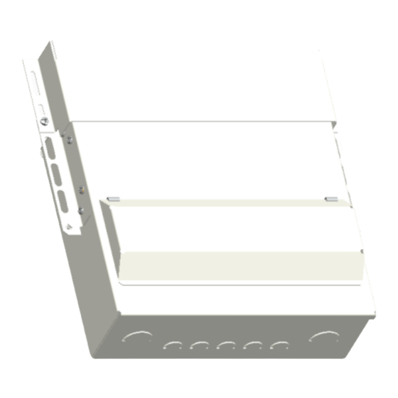
1. Enclosure Mounting
•
Remove appropriate KO's, cover and outer cable shroud from the
enclosure. Note, the top gland plate can be removed for ease of
KO removal.
•
The unit must be mounted with the gland plate facing upwards.
•
Mount the unit into its installation position, Both 'L' brackets
provided must be fitted in positions 'a' OR 'b', see Fig 2.1. When
installed the base of both 'L' brackets should sit flush against the
enclosure back wall in order to support the unit. Assess which 'L'
bracket position (a OR b) best suits the installation and which
bracket fixing holes should be used (the depth of the bracket fixing
can be adjusted using the various bracket holes). Remove the unit
from the installation.
•
Remove the appropriate 'L' bracket fixing blanks from positions 'a'
OR 'b' (4 per bracket) by drilling or knocking out from the inside of
the unit. The baseplate should be removed to aid the 'L' bracket
installation.
•
Use the following fasteners provided to attach each 'L' bracket to
the box: 4 x M5 screws, 4 x M5 nuts and 8 x M5 serrated washers,
See Fig. 2.1.
•
Mount the unit into its installation position. Secure the wing fixings
first using M6 fixings. Both 'L' brackets should then be screw-fixed
with M6 size screws (not supplied) to the cabinet back wall. See
Fig. 2.2.
•
Check the unit is securely mounted.
Recommended
tightening torque
2
50mm
2.3Nm
2
25mm
2.3Nm
2.0Nm
2
- 16mm
2.5Nm
2.0Nm
2
- 16mm
2.5Nm
2
16mm
1.7Nm
Page 1 of 2
Advertisement

Summary of Contents for WYLEX AM3
- Page 1 Installation instructions, AM3 SKELETON (L TYPE) FIXED BUSBAR RANGE IMPORTANT INFORMATION This unit should be installed by a qualified competent person in accordance with all relevant legislation and regulations including building regulations and wiring regulations BS7671. If in doubt contact a qualified competent person.
- Page 2 Only NHX range MCBs and NHXSBS range RCBOs must be used • The outer cable shroud should be fitted after the front cover is within Wylex AM3 skeleton range consumer units. • fitted. The shroud is screwed directly to the unit fixing wings.
Need help?
Do you have a question about the AM3 and is the answer not in the manual?
Questions and answers