
Summary of Contents for Eco Power Equipment IAQH Series
- Page 1 Installation and User Instructions IAQH Construction Heater IAQH-1000 / 1,000,000 BTU Indirect Fired These are the original English instructions August, 2021 Version 1.2 ©Eco Power Equipment Ltd.
- Page 2 ©Eco Power Equipment Ltd.
- Page 3 Neither Eco Power Equipment Ltd. nor any of its affiliates or subsidiaries shall be responsible or liable for misuse of the information that is contained herein. If you have any suggestions for improvements or amendments or have found errors in this publication, please notify us.
- Page 4 TRADEMARKS Eco Power Equipment Ltd. has made every effort to supply trademark information about company names, products and services mentioned in this manual. Trademarks shown below were derived from various sources. All trademarks are the property of their respective owners.
-
Page 5: Table Of Contents
Documentation Feedback Support and service DESCRIPTION OF THE PRODUCT Intended Use and Reasonably Foreseeable Misuse Process Overview Technical Data Product Compliance Product Elements Machine guards Understanding the user interface Operating Panels Explanation Visual Signals Lifting Lifting accessories ©Eco Power Equipment Ltd. - Page 6 Specifications of Tools/Hand Tools to be Used PREPARATION How to Transport and Store the Product Dimensions, mass and centre of gravity Lifting, handling, and transporting the product Storing the product How to Install the Product Packaging contents ©Eco Power Equipment Ltd.
- Page 7 What to Do in Emergency and Exceptional Situations Emergency Situation MAINTENANCE How to Maintain the Product Product maintenance by non-skilled persons Cleaning and Storage Product maintenance by skilled persons Maintenance Items How to Inspect the machinery ©Eco Power Equipment Ltd.
- Page 8 Troubleshooting and repair by non-skilled persons Troubleshooting and repair by skilled persons IAQH F4T Controller Troubleshooting: LME Burner Management System DISPOSAL How to Dispose the Product Disposal of electronic components RELATED DOCUMENTATION INSTALLATION FORM & CHECKLIST WIRING DIAGRAMS ©Eco Power Equipment Ltd.
-
Page 9: Preface
This document is intended for the equipment operator and the equipment installer of the IAQH. The IAQH series of indirect fired heaters are designed to support temporary construction heating applications that support a wide variety of temporary heating. The user of the product is intended to be qualified to install and connect the system. - Page 10 IAQH-1000 Manual User input variables < > Angle brackets surround user-supplied values Square brackets surround optional items Vertical bar indicates alternate selections - the bar means “or”...
-
Page 11: Explanation Of Safety Warnings
IAQH-1000 Manual Explanation of Safety Warnings Danger indicates a hazardous situation that, if not avoided, will result in death or serious injury Warning indicates a hazardous situation that, if not avoided, may result in death or serious injury. Caution indicates a hazardous situation that, if not avoided, may result in minor or moderate injury. -
Page 12: Obtaining Documentation And Information
This is the English user manual. Manuals in French are available upon request. Documentation Feedback If you are reading Eco Power Equipment Ltd. product documentation on the internet, any comments can be submitted on the support website. Comments can also be sent to info@ecopowerequip.com. -
Page 13: Description Of The Product
Your local authority can advise you about these other standards. The IAQH shall be used with the following original accessories and components only: ● Eco Power Equipment EHT and ERA Type Ducting ● IAQH Remote Thermostat ● IAQH Temporary Flue System... -
Page 14: Process Overview
IAQH-1000 Manual Process Overview The indirect heat transfer process relies on the heat from the heat exchanger to heat the air through convection, conduction, and radiation. The combustion air does not come in direct contact with air in this process. -
Page 15: Technical Data
IAQH-1000 Manual Technical Data Parameter Unit Device name IAQH Indirect Fired Heater Designation IAQH-1000 Type Indirect Fired Technical life span 10,000+ Hours Maximum Input BTU 1,000,000 BTU/HR / 293 kW Natural Gas: 1.0551 GJ/hour, 985 ft³/hour, 27.89 m³ hour Energy consumption Liquid Propane: 41.32 LPH / 10.92 GPH Natural Gas: (Pipeline Quality) (1075 BTH/ft³) (40.1 MJ/m³) -
Page 16: Product Compliance
IAQH-1000 Manual Product Compliance This product complies with all relevant legislation for portable gas fired construction heaters. The product is in conformity with the following relevant product safety standards: ● ANSI Z83.7-2017: Gas fired construction heaters ● CSA 2.14-2017: Gas fired construction heaters ●... -
Page 17: Product Elements
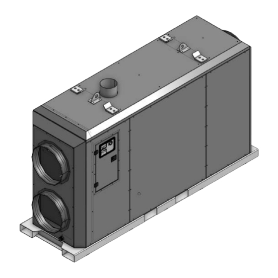
IAQH-1000 Manual Product Elements A. Element A: Combustion Exhaust Flue Connection Point, 8” B. Element B: Lifting Points Connection - See lifting guide below C. Element C: Stacking Points D. Element D: Unit control and operating panel E. Element E: Forklift Pockets F. - Page 18 IAQH-1000 Manual Element A: Heated Air Outlet, 24” Round Element B: Burner Control Panel and Burner Management System (BMS) Element C: Fuel Gas Inlet, 10” WC, 1-¼” NPT...
-
Page 19: Machine Guards
IAQH-1000 Manual Machine guards A. Guard A: Inlet fan guard system. Ensure the inlet is free and clear. We recommend filtration for inlet make-up air. -
Page 20: Understanding The User Interface
IAQH-1000 Manual Understanding the user interface The main user interface of the machine is located in the operating and control panel of the machine. The system utilizes a touchscreen display to allow the user complete control over the unit’s operation. When looking at the front panel of the display, at the bottom of the display are four push buttons. - Page 21 IAQH-1000 Manual...
- Page 22 IAQH-1000 Manual...
-
Page 23: Operating Panels
IAQH-1000 Manual Operating Panels Main Control and Operating Panel: The main operating panel has all the items required to control, operate and use the system.. - Page 24 IAQH-1000 Manual Burner Control Panel (BMS): Item# Part # Description 8429-78 SCEBM-2 Fan Control 8447-28 120/208/24vac – 24V 40VA Transformer 8402-50 Pilot Solenoid Valve 8409-25 Terminal Block 8406-98/99 Relay “B” 8406-95/96 Relay “A” 8425-56 Air Pressure Switch 8423-05 On/Off Switch 8447-22 Ignition Transformer 8447-39...
-
Page 25: Explanation Visual Signals
IAQH-1000 Manual Explanation Visual Signals The IAQH-1000 has multiple visual signals within the unit pertaining to different aspects of machine operations The limit fault light is located at the main control panel. This light becomes active in the event of the one or multiple of the following conditions: High Limit, Tilt Switch Activation, or Burner Management System Fault - in a high limit condition it is recommended that the user look at the display of the Siemens BMS manager for LOC code, this will provide detail into the lock out... - Page 26 IAQH-1000 Manual SCEBM-2 Module is designed to control the speed of the combustion blower based on three input signals and several programmable parameters. It is used to set and tune the combustion air for the burner system. It also automatically stages the combustion motor during the trial for ignition phase.
-
Page 27: Lifting
IAQH-1000 Manual Lifting Lifting accessories The lifting bail is classified as a "below-the-hook" lifting device; as such, in order to meet the requirements of ASME BTH-01 and B30.20 the lifting bail assembly must undergo an MPI (magnetic particle inspection) by qualified personnel after manufacture on an annual basis. The inspection must conform to B30.20 and OH&S requirements. -
Page 28: Safety Instructions
IAQH-1000 Manual C. SAFETY INSTRUCTIONS Read and understand this manual and its safety instructions before using this product. Failure to do so may result in serious injury or death. How to Use the Product Safely General Hazard Warning ● FAILURE TO COMPLY WITH THE PRECAUTIONS AND INSTRUCTIONS PROVIDED WITH THIS HEATER CAN RESULT IN DEATH, SERIOUS BODILY INJURY, AND PROPERTY LOSS OR DAMAGE FROM HAZARDS OF FIRE, EXPLOSION, BURN, ASPHYXIATION, CARBON MONOXIDE POISONING, AND/OR ELECTRICAL... -
Page 29: Personal Protective Equipment
IAQH-1000 Manual ● Examples of Misuse: o Permanent Heating Applications o Connecting the unit to inappropriate voltage or gas pressure o Operating the machine in a manner that is inconsistent with any federal, provincial, or local codes and regulations o Operating the machine outside of factory specifications o Operating the machine in a manner inconsistent with any warnings found on the machine or in the Operator’s Manual ●... -
Page 30: Installation Safety Information
IAQH-1000 Manual Installation safety information ● All gas inspection authorities in Canada require that the installation and maintenance of the heater and accessories shall be accomplished by a qualified gas fitter. ● This equipment has been test fired and inspected before shipping. It has been shipped free from defects from our factory. -
Page 31: Graphical Symbols
IAQH-1000 Manual Graphical Symbols Explanation of safety information on the packaging and product Symbol Meaning Indicates a hazardous situation that, if not avoided, will result in death or serious injury. Indicates a hazardous situation that, if not avoided, may result in death or serious injury. - Page 32 IAQH-1000 Manual fired—meaning the combustion byproduct does not enter the air space; however, all construction environments should be set up with proper mechanical ventilation (make-up air). Do not use the system in unventilated areas. Know the signs of CO and CO poisoning: ●...
-
Page 33: Personal Protective Equipment
IAQH-1000 Manual ● Local codes vary, but are adopted and enforced to promote safe electrical installations. A permit may be needed to do electrical work, and some codes may require an inspection of the electrical work. Personal Protective Equipment Instruction Job Site Standard Follow your local jobsite requirements Eye Wear... -
Page 34: Preparation
IAQH-1000 Manual D. PREPARATION How to Transport and Store the Product Safe transport of equipment to and from job sites is critical, always ensuring to properly secure and affix units during transportation, using proper hold down points and lifting points in accordance with factory guidelines. -
Page 35: Lifting, Handling, And Transporting The Product
IAQH-1000 Manual Lifting, handling, and transporting the product The IAQH-1000 system is designed to be lifted and transported in a number of different ways to facilitate quick, simple, and safe deployment and movement of the unit. To lift the product safely: 1. -
Page 36: Storing The Product
IAQH-1000 Manual To handle the product safely: 1. Existing fork pockets are designed to allow the use of an appropriately rated forklift to move and locate the unit on location 2. Side pocket spacing is such that an appropriately rated pallet jack can be utilized to move and place unit on sides where a pallet jack is appropriate To transport the product safely: 1. - Page 37 IAQH-1000 Manual To store the product safely: 1. Clean and blow out control panel 2. Disassemble and clean oils from gas train components 3. Cover inlet and outlet vents to avoid contamination during the summer months 4. Cover and seal exhaust chimney 5.
-
Page 38: How To Install The Product
IAQH-1000 Manual How to Install the Product The installation must conform with local codes or in the absence of local codes with the Standard for the Storage and Handling of Liquified petroleum Gases, ANSI/NFPA 58 and/or the National Standards of Canada CAN/CGA B149.2/3 installation codes. The heater must be located more than ten (10) feet (3.05 meters) away from the propane source or propane tank. - Page 39 IAQH-1000 Manual Minimum space needed This unit must be installed with a minimum clearance of 7” (180 mm) on the non control panel side, 20” (510 mm) on the control panel side, 18” (460 mm) from the top of the unit, 18” (460 mm) from the flue venting, 18”...
-
Page 40: Layout Plan
IAQH-1000 Manual Layout Plan Indoor Mounted System: This unit is designed to be mounted internally into the structure it is heating, following all clearance distances found in Section 4.2.2. Ensure the unit is only installed onto a non-combustible floor. Horizontal Venting: Venting must be done in accordance with CSA B149.1 or NFPA 54 or with appropriate local authorities having jurisdiction. - Page 41 IAQH-1000 Manual Fig. 5 -Vent installation shall confirm with local codes or in the absence of codes with the National Gas and Propane Installation Code, CSA B149.1, CSA B149.3, or ANSI Z223.1/NFPA 5 1. Maximize the height of the vertical run of the vent pipe. A minimum of three feet (0.91 m) of vertical pipe is required at the heater.
- Page 42 IAQH-1000 Manual 2. Horizontal runs must not exceed 75% of the vertical height of the vent pipe, up to a maximum of ten (10) feet (3 m). Horizontal runs should be pitched upward ¼” per foot (6.35 mm) and should be supported at 8 foot (2.44 m) maximum intervals. 3.
- Page 43 IAQH-1000 Manual Exterior Mounted System: This unit is designed to be mounted externally to the structure it is heating, following all clearance distances found in Section 4.2.2. Ensure the unit is installed onto a non-combustible surface. To maximize heating system efficiency it is recommended to pull a portion of return air from the structure.
- Page 44 IAQH-1000 Manual The exhaust venting chimney must maintain the following clearances from the building area or structure. Structure / Object Minimum Clearance Air Intake 0.9m (3’) above and 1.8m (6’) to the side Combustion air intake from another heater 1.8m (6’) above and 1.8m (6’) to the side Door, openable window, revolving door 1.8m (6’) to the side or all other openings...
-
Page 45: Installation Of Iaqh
IAQH-1000 Manual iii. Installation of IAQH Required tools: ● Multimeter ● Combustion Analyzer ● 2 x Manometer (s) ● Basic Hand Tools Including: Screwdrivers, Wrenches, Pipe Wrenches These instructions have been thoroughly written, but they cannot cover every particular installation and contingency. Therefore, if there is any doubt as to the interpretation of any requirements, contact your local authority having jurisdiction, your local dealer, or Eco Power Equipment Ltd. - Page 46 IAQH-1000 Manual 7. Ensure that the burner intake vents are not blocked and that debris or snow will not enter the enclosure during normal operation. 8. Do not place the unit in close proximity to alternate heat sources. Maintain 6 feet (2 meters) of clearance.
-
Page 47: Installation Checklist
IAQH-1000 Manual 12. Combustion Air a. The burner requires combustion air and ventilation air for reliable operation. Assure that the Building and/or combustion air openings comply with National Fuel Gas Code NFPA 54/CSA B149. For appliance/burner units in confined spaces, the room must have an air opening near the top of the room plus one near the floor, each with a free area at least one square inch per 1000 Btu/hr input of all fuel burning equipment in the room. -
Page 48: Duct Connecting
IAQH-1000 Manual Duct Connecting 1. It is recommended to only use Eco Power Equipment brand ducting for your IAQH heater. a. Inlet Ducting shall be vinyl type ductings with a minimum 4” pitch for sewn in helical coil, with a cuff and buckle type connections b. -
Page 49: How To Commission And Tune The Burner System
IAQH-1000 Manual How to Commission and Tune the Burner System Training of operators Contact the factory for operation and service training program information. Ensure that all tasks are performed by qualified individuals, and note that many tasks may be required to be performed by ticked journeyman professionals. -
Page 50: Gas Connection And Burner Setup
IAQH-1000 Manual Gas Connection and Burner Setup FIgure GT1... - Page 51 IAQH-1000 Manual Item # Part # Description 2120-01 Control Box 2101-01 Burner Housing Main Gas Manifold Pressure Tap Manual Firing Valve Ratio Regulator AIr Pressure Tap 8614-04 Dungs FRG Ratio Regulator Low Fire Bypass 8402-42 Main Gas Solenoid 1 8402-42 Main Gas Solenoid 2 8416-05 Main Gas Regulator...
- Page 52 IAQH-1000 Manual Step by Step Commissioning Instruction: 1. Use only 1-1/4” NPT gas pipe, the unit is designed for 10 inH20 or 25 mBar or 2.5 kPa inlet pressure operating under load 2. Seal all connections using a thread joining compound approved for natural gas & propane 3.
- Page 53 IAQH-1000 Manual 9. Set Pilot Pressure: a. With the burner and fuel off, install a barb fitting on the 1⁄8′′ NPT pressure tap downstream of the pilot regulator, this tap is located on the side of the solenoid valve, always pull from the downstream solenoid closest to the burner pilot (See Figure GT1, Item 14) b.
- Page 54 IAQH-1000 Manual 11. Adjust and Verify Main Gas Regulator: a. Turn the burner up to its maximum firing rate by changing HX Control Loop to manual and power to 100% b. Use a manometer to check the inlet pressure on the tee on the upstream side of the pilot regulator, see See Figure GT1, Item 12 c.
- Page 55 IAQH-1000 Manual e. If necessary, turn the screw on the ratio regulator, see Figure Midco 1 below, in order to adjust the manifold pressure. This is done by removing the black plastic cap, and using a flat head screwdriver to adjust the set point.
- Page 56 IAQH-1000 Manual Figure RTC Figure Midco 1...
- Page 57 IAQH-1000 Manual Figure RTC 2...
- Page 58 IAQH-1000 Manual 14. Excess Air Adjustment: a. If the burner is operated at any firing rate lower than maximum capacity, there is a possibility to have too much excess air. To increase excess air, loosen the nut on the air orifice plate and slide it outward.
-
Page 59: How To Use The Machinery
IAQH-1000 Manual OPERATION/USE How to Use the Machinery The installation shall conform with local codes, or, in the absence of local codes, with the National Fuel Gas Code, ANSI Z223.1/NFPA 54, or the National Gas and Propane Installation Code, CSA B149.1 Heating Mode Turn on the main power disconnect switch, if the ambient temperature is less than 5 °C or 41 °F, wait 10–15 minutes for the control panel heater to bring control system up to... -
Page 60: Manual Operating Techniques
IAQH-1000 Manual fans will automatically turn down to maintain optimal efficiency and decrease operating power requirements. 8.1.1 Manual operating techniques The fan system can be placed into 100% output mode to allow the fans to be at a constant max output. -
Page 61: Starting/Stopping The Product's Operation
IAQH-1000 Manual 8. Follow the same process and place the control loop back into AUTO mode 9. WARNING: This overrides the control loop and can cause the heater to overheat and shutdown, and should only be used by trained personnel for the purpose of commissioning the unit or advanced troubleshooting —... -
Page 62: Switching Between Fuel Sources
IAQH-1000 Manual 8.2 Switching Between Fuel Sources It is common for customers who use the IAQH-1000 heating system to switch between fuel sources as they become available during the construction process. This typically involved starting projects on propane fuel, and switching to natural gas when it becomes available. -
Page 63: What To Do In Emergency And Exceptional Situations
IAQH-1000 Manual 8.4 What to Do in Emergency and Exceptional Situations 8.4.1 Emergency Situation In case of an emergency situation: 1. Turn off gas valve at the gas source, there are also valves at the unit 2. Turn off power by opening source circuit breaker, or main disconnect switch 3. -
Page 64: Maintenance
IAQH-1000 Manual 9 MAINTENANCE The IAQH shall only be maintained by a qualified and trained person. Proper annual maintenance is a very important part of maintaining high performance, high reliability heating solutions. How to Maintain the Product 9.1.1 Product maintenance by non-skilled persons 9.1.1.1 Cleaning and Storage Cleaning the unit with standard water and soap, never use a pressure washer in burner... -
Page 65: How To Inspect The Machinery
IAQH-1000 Manual 9.2 How to Inspect the machinery 9.2.1 Weekly inspection tasks Task Action Inspect for abnormal wear Review all components Leak Test Gas Train and Gas System 9.2.2 Annual Inspection tasks Task Action Heat Exchanger Review for cracks and leaks Burner Maintenance Remove and clean burner and ignition system... -
Page 66: Troubleshooting And Repair
IAQH-1000 Manual 10 TROUBLESHOOTING AND REPAIR 10.1 How to Identify and Solve Problems 10.1.1 Troubleshooting and repair by non-skilled persons Our heating systems are designed to deliver high reliability and uptime. The number one and two causes of operational issues are related to fuel or power related issues. It is essential that the proper voltage and gas pressure are maintained to the unit. -
Page 67: Troubleshooting And Repair By Skilled Persons
IAQH-1000 Manual 10.1.2 Troubleshooting and repair by skilled persons Advanced diagnostics and troubleshooting should only be done by skilled, qualified professionals who have read and understood this manual, and preferably undergone a detailed factory training program. IAQH F4T Controller Troubleshooting: ●... - Page 68 IAQH-1000 Manual ● ● Current Error Load Current Shorted solid-state or Replace relay ● incorrect mechanical relay Route load wire through current transformer from ● Open solid-state or correct output, select the output that is driving the mechanical relay load. ●...
-
Page 69: Lme Burner Management System
IAQH-1000 Manual Burner Management System Panel Troubleshooting Guide LME Burner Management System The LME7 has an extensive list of fault codes to help clarify the nature of any fault. The next pages describe every fault code in detail and give guidance on how to correct it. When a fault occurs, the LME7 will alternate between displaying “Loc”... - Page 70 IAQH-1000 Manual Parameter 701 displays information about the current status of the LME7. Parameter 702 displays information about the most recent fault. Parameter 703 displays information about the second most recent fault. Parameter 711 displays information about the 10th most recent fault. Each fault code listed has indexes that provide additional information about the fault: Index 00 = Fault code Index 01 = Start number...
- Page 71 IAQH-1000 Manual Resetting Faults on the LME7 Burner Control Faults can be reset in one of three ways on the LME7… burner control: 1. Pressing the info button on the LME7 burner control for 1-3 seconds. Note: Pressing the info button for less than one second has no effect. Pressing the info button for more than three seconds places the LME7 into diagnostic mode.
- Page 72 IAQH-1000 Manual LME7 BMS Complete Fault Code List Fault Description of Corrective Action Code the Fault A flame failure occurred during light off. 1. Check the wiring of the ignition transformer, pilot valve, and main valve(s). 2. Ensure manual shutoff valves on the pilot gas line and main gas line are open.
- Page 73 IAQH-1000 Manual The required position feedback from the connected SQM… actuator was not received. 1. Ensure the potentiometer on the SQM… actuator is wired correctly. -For counter-clockwise actuators (SQM40…, SQM50…), terminal "c" on the potentiometer should be wired to terminal X66.1 on the LME7, and terminal "a" on the potentiometer should be wired to terminal X66.3 on the LME7.
- Page 74 IAQH-1000 Manual On PME73.840A1, the upstream gas valve V1 failed valve proving. On all other PME7 program modules, the downstream gas valve V2 failed valve proving. Fuel valve V1 leaking 1. Bubble test the gas valve to ensure the valve is not (PME73.840A1) Fuel valve leaking.
- Page 75 IAQH-1000 Manual The speed of the PWM blower does not match the expected speed. More specifically, the blower speed fell outside of tolerance band 1 (parameter 650.00) for a time longer than the maximum speed deviation allowed (parameter 660), or the blower speed fell outside of tolerance band 2 (parameter 650.01).
- Page 76 IAQH-1000 Manual One or more PWM blower settings are not compatible. Make sure the following three conditions on the minimum and maximum speed settings are met. PWM blower 1. 516.00 ≤ P0 ≤ 516.01 parameterization error 2. 517.00 ≤ P1 ≤ 517.01 3.
-
Page 77: Disposal
IAQH-1000 Manual 10.2 DISPOSAL 10.3 How to Dispose the Product To dispose the product: 1. Review all components and dispose / recycle in line with your local guidelines and laws 10.3.1 Disposal of electronic components The symbol on the product, the accessories or packaging indicates that this device shall not be treated as unsorted municipal waste, but shall be collected separately! Dispose of the device via a collection point for the recycling of waste electrical and electronic equipment if you live within the EU and in other European countries that operate separate collection systems for waste... -
Page 78: Related Documentation
IAQH-1000 Manual RELATED DOCUMENTATION Document Title Version # IAQH-1000: Electrical Schematics Rev. A Technical Instructions LME-1000 June 11,2019 Midco Unipower VA Series Installation and Service 8471 95 Manual F4T® Controller Setup and Operations User Guide 1680-2414 Rev. D IAQH Installation Form and Checklist Rev A. -
Page 79: Installation Form & Checklist
IAQH-1000 Manual INSTALLATION FORM & CHECKLIST Job Location: Technician Name: Unit Model Number: Unit Serial Number: Job Elevation: System Voltage Off: System Voltage Full Load: Gas Type: Inlet Gas Pressure with Machine Off: Inlet Gas Pressure at High Fire: Set Air Ratio Regulator for appropriate fuel (Propane or Natural Gas, see section 4.3) Manifold Pressure @ High Fire: Checklist Unit Clean and Fully Assembled:... - Page 80 IAQH-1000 Manual Combustion Analysis Efficiency Stack Temperature Ambient Temperature Excess Air...
-
Page 81: Wiring Diagrams
For high resolution wiring diagrams, scan the QR code fixed to your specific unit or visit: Http://www.ecopowerequip.com/iaqh-1000man Wiring Diagrams are confidential and proprietary to Eco Power Equipment Ltd - do not duplicate or distribute without express written permission. Note: Always ensure that you scan and reference your specific unit and have the correct drawing... - Page 82 IAQH-1000 Manual 1-833-249-2417 / 1-780-483-0700 #8, 26004 Township Road 544 Sturgeon County, AB, T8T 0B6, Canada www.ecopowerequip.com info@ecopowerequip.com...
Need help?
Do you have a question about the IAQH Series and is the answer not in the manual?
Questions and answers