
Summary of Contents for SIMTRUM NANYTE BEAM
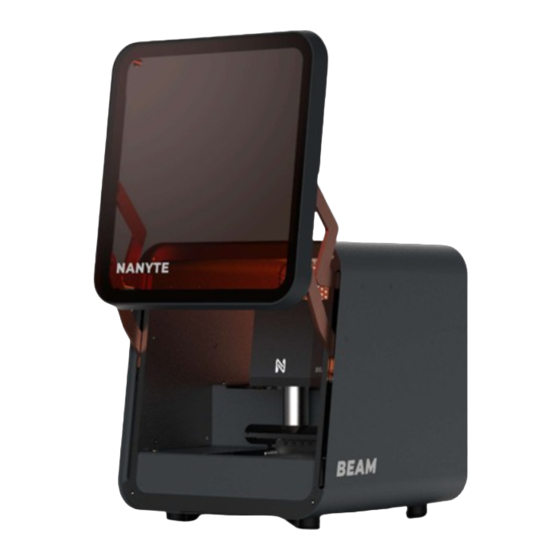
- Page 1 NANYTE BEAM Desktop Maskless Lithography User Manual BM-001-A3 / June 2022 www.simtrum.com...
-
Page 2: Table Of Contents
NANYTE BEAM Manual Contents Contents............................2 Getting Started ........................4 Safety Precautions ..........................4 Laser Safety ............................5 Maintenance ............................5 Contact Information .......................... 6 Packing List ............................6 Unpacking and installation ....................... 6 Product overview ..........................6 Specifications ............................ 8 System requirements........................ - Page 3 NANYTE BEAM Manual Laser calibrations ........................... 30 PI curve ............................30 Spatial power calibration ......................30 Stage levelling ..........................31 Focus calibration ..........................31 Calibrating the autofocus ......................31 Calibrating the laser beam spot focus offset ................32 Troubleshooting ........................33...
-
Page 4: Getting Started
NANYTE BEAM Manual Getting Started Safety Precautions The following safety precautions should be observed before using this product and any associated instrumentation. This product is intended for use by qualified personnel who recognize shock hazards and are familiar with the standard lithography processes. Read and follow all installation, operation, and maintenance information carefully before using the product. -
Page 5: Laser Safety
NANYTE BEAM Manual Laser Safety During operation, NANYTE BEAM uses <5 mW of laser radiation to cure the UV-sensitive photoresist. For increased safety to operator, the equipment is equipped with a laser interlock system to prevent accidental exposure to 405 nm light. Located on the bottom side of the front door, the magnetic door catch/interrupt can detect if the front door is closed properly. -
Page 6: Contact Information
Packing List Due to its low weight and compact size, NANYTE BEAM is shipped in a 50 x 50 x 50 cm corrugated cardboard box with foam protection. - Page 7 A h-line laser light source is used and is compatible with a wide range of resists. The BEAM ENGINE can be upgraded to use other light sources. Please contact your local representative for this upgrade. Below are some samples patterned with NANYTE BEAM. 50 µm NANYTE BEAM Manual BM-001-A3 / V1.1a...
-
Page 8: Specifications
NANYTE BEAM Manual Specifications The following tables detail the design specifications of NANYTE BEAM. Patterning 2 µm guaranteed Minimum Linewidth 0.8 µm achievable Minimum Pitch 1.6 µm achievable Exposure Time < 2 s for 1 writefield 400 µm ✕ 400 µm... -
Page 9: System Requirements
NANYTE BEAM Manual System requirements Power BEAM operates on 100-240 VAC 50-60 Hz. Line voltage and frequency are automatically sensed; therefore, no switches are to be set. Check that the operating voltage in your area is compatible. CAUTION – Operating the equipment on an incorrect line voltage may cause damage, possibly voiding the warranty. -
Page 10: Front View
3500 2000 The standard NANYTE BEAM is shipped with the Nikon 20x option. The theoretical resolution is calculated from the numerical aperture of the objectives, while the achievable linewidth is empirically determined from testing. The values listed are for reference and may greatly differ (increased or even decreased) due to process parameters. - Page 11 NANYTE BEAM Manual distance is the distance from the bottom of the objective to the top of the sample. For the Nikon 20x objectives, the working distance is 1 mm means that the sample can potentially be driven into the objectives. Caution should be exercised when focusing.
-
Page 12: Beam Engine
NANYTE BEAM Manual BEAM ENGINE ELECTRICAL INTERFACE The electrical interface on the BEAM ENGINE consists of three sets of connections. 1. USB 3.0 Micro connection 2. 16-pin IDC ribbon connection to the motion controller 3. 6-pin IDC ribbon connection to the encoder BACKLIT LOGO INDICATOR Provides information about the system status. -
Page 13: Back View
NANYTE BEAM Manual Back View ON/OFF SWITCH Controls the AC power supply to the system. FUSE DRAWER Holds two 240V fuse, with one for spare. For replacement, use 20 x 5 mm 3.15A cylindrical speed F fuse. RS Part: 537-1155. -
Page 14: Xplorer Main Window
NANYTE BEAM Manual XPLORER Main Window Preview window Acts as a minimap of the entire sample stage. Loaded patterns and exposed areas can be viewed. The black box shows the region that the BEAM ENGINE is currently at. The live video stream on the camera window also corresponds to the same area. - Page 15 NANYTE BEAM Manual Loaded Pattern When a compatible file is loaded for exposure, it is shown in blue. During exposure, red shapes are overlaid on top to indicate which area has been exposed. Terminal Output The terminal shows important information through text. These can be: 1.
- Page 16 NANYTE BEAM Manual brightness is limited to 90%. Once the slider is moved, the appropriate exposure time is automatically calculated. Stepper controls XYZ input boxes: The text boxes allow the operator to key in any position to move the BEAM ENGINE to.
- Page 17 NANYTE BEAM Manual Patterning controls Contains the all the actions required to perform patterning. The controls are discussed in detail in the patterning section. NANYTE BEAM Manual BM-001-A3 / V1.1a Page 17 of 33 www.simtrum.com...
-
Page 18: Camera Window
NANYTE BEAM Manual Camera Window The camera window shows a live stream of what the BEAM ENGINE is looking at. The camera window also plays an important role during alignment, where the chosen alignment features appear overlaid on the camera stream. -
Page 19: Keyboard/Mouse Shortcuts
NANYTE BEAM Manual Keyboard/Mouse Shortcuts ‘W’, ‘A’, ‘S’, ‘D’ : Moves the BEAM ENGINE upwards, leftwards, downwards and rightwards, respectively. : Moves the BEAM ENGINE upwards, leftwards, downwards and rightwards, ↑ ← ↓→ respectively. ‘Shift’ : When pressed with the above movement keys, the speed at which the BEAM ENGINE moves is greatly increased. -
Page 20: Patterning
NANYTE BEAM Manual Patterning NANYTE BEAM was designed so that the least number of steps are necessary to do a full exposure. Depending on the complexity of the patterning job, it is possible to load, align and expose a pattern onto a wafer in under 3 minutes. The flow of the entire patterning process is... -
Page 21: Load Gds
NANYTE BEAM Manual We suggest visiting the MicroChemicals website to see their entire range of photoresists. After spin coating, it is usual to have a soft-bake. For resist-related processes, please refer to the product’s datasheet instead. Loading NOTE: Before placing the sample, please check that the back surface of the sample is clean; it is not unusual to have resist stains on the back of the sample, due to resist residue on the spin coater chuck. - Page 22 NANYTE BEAM Manual 3. A GDS preview window will appear for the loaded GDS file. Since a GDS file can contain multiple layers, a layer must be chosen for the exposure. To navigate in the GDS preview window, the same mouse actions for the Main control preview window can be used. To help with the visualization, the patterns are color-coded and the legend is located on the top right corner of the window.
-
Page 23: Load Image Files
NANYTE BEAM Manual An option is also provided to invert the layer for use with negative photoresists. A 15 um offset from the layer is created. This offset area will be exposed. 5. Clicking Ok, the GDS pattern will be loaded on to the main control preview window. -
Page 24: Draw Patterns
NANYTE BEAM Manual 2. A load bitmap window will appear and provide several patterning options (see above). To navigate on the pattern preview, use similar controls as the preview window. X and Y repeats allow the creation of arrays. X and Y offset controls the distance between adjacent patterns in an array. -
Page 25: Alignment
NANYTE BEAM Manual 3. Text can also be added to label patterns. Click on the Text button on the top left of the camera window, the below dialog will appear. Enter any text that you wish to create and click ok. The text pattern can also be moved around by dragging and deleted by right clicking and select delete. - Page 26 NANYTE BEAM Manual 2. Alignment is performed with four points. Hence, it is necessary to repeat the below steps four times. To perform alignment, navigate the BEAM ENGINE to a feature that you wish to align to. The feature should be close to the center of the camera window. Next, using zoom (mouse scroll) and translate (Left-click and drag), locate the corresponding feature on the preview window.
-
Page 27: Exposure
1. Ensure that the correct UV expose power is used. You can access this setting on the main window. The value corresponds to mJ/cm 2. Click the slice button to generate the toolpath for NANYTE BEAM. For simple exposures, this process should take less than a second. For complex exposures, a loading bar will appear and the number of write fields that have been processed compared to the total write fields will show. -
Page 28: Calibration
The purpose of this section is not to encourage operators to perform calibration, but rather for better understanding of the operation principles of the system. Three coordinate systems are used by NANYTE BEAM: 1. Stepper coordinates (microns, 100 nm resolution) 2. -
Page 29: Galvo Scanner Position Calibration
NANYTE BEAM Manual Galvo scanner position calibration The galvo controls the position of the laser beam spot, with respect to the camera coordinates. Calibration is required because optical aberrations such as pincushion can severely distort the galvo coordinates by few microns. A second order fitting with 10 coefficients is used to map the galvo coordinates to the camera coordinates. -
Page 30: Laser Calibrations
NANYTE BEAM Manual Laser calibrations PI curve Besides the spatial calibrations, the laser output should also be calibrated. This is especially because the laser power does not vary linearly with laser current. A photodiode is installed within each BEAM ENGINE that allows for self-calibration. Click the calibrate button to start the calibration. -
Page 31: Stage Levelling
NANYTE BEAM Manual Stage levelling To ensure that the stage is parallel to the x and y stepper axis, stage levelling is required. Insert a large polished silicon substrate (> 3 x 3 cm) onto the sample stage and position BEAM ENGINE on the silicon substrate. -
Page 32: Calibrating The Laser Beam Spot Focus Offset
NANYTE BEAM Manual Calibrating the laser beam spot focus offset It is possible for the laser beam spot to be focused at a level that is different from the sample surface. This also provides an opportunity to tune for the sidewall profile. Typically, high resolution features in far field optics will require a large beam cone angle. -
Page 33: Troubleshooting
NANYTE BEAM Manual Troubleshooting For any calibration procedure, ensure that the operator is trained and familiar with the calibration procedure. Symptom Action Camera window is completely black. Turn on the LED on the main window. Second layer alignment is more than 1 Perform galvo position calibration.
Need help?
Do you have a question about the NANYTE BEAM and is the answer not in the manual?
Questions and answers
Hello, why the slicing is so slow and finally cannot pattern after 2 hours?
The slicing may be slow and unable to pattern after 2 hours with the SIMTRUM NANYTE BEAM due to resist residues on the spin coater chuck. These residues can cause small samples to tilt, which may lead to autofocus failure and prevent proper patterning.
This answer is automatically generated