Table of Contents
Advertisement
Quick Links
Advertisement
Table of Contents

Summary of Contents for TECHNOJET FZE TJ560C
- Page 1 TJ560C Continuous Ink Jet Printing System TECHNOJET FZE...
- Page 2 TJ560C Continuous Ink Jet Printing System User Guide Revised 07/08/2019 PN# 20190006 Rev – Ver1.0...
-
Page 3: Table Of Contents
Contents Introduction ..........................5 Printing System Specifications ..................6 Components ..........................7 Top View ..........................7 Front View .......................... 8 Side View ..........................8 Printhead View ......................... 8 Equipment Setup ........................9 Printing System Component ..................9 Installation and Setup Instructions ................. 10 Operation .......................... - Page 4 “Ambient temp. high warning” ................... 51 “Electrical temperature too high” warning............51 “Viscometer fault” warning ..................51 “Ink bottle chip fault” warning .................. 52 “Solvent bottle chip fault” warning ................53 “Filter assembly fault” warning ................. 53 “Ink shortage”...
-
Page 5: Introduction
This printer will provide you with quality coding on a variety of substrates: porous, non-porous, smooth, textured, curved, concave and more. Printing up to 5 lines (5x5 dot matrix) of text, TJ560C printer offers a reliable, yet cost effective solution for virtually any small character primary packaging application. -
Page 6: Printing System Specifications
Printing System Specifications Nozzle size 60µm (standard) Dot matrix 5x5,7x5,9x7,12x12,16x16,24x24 and 32x32 Printing height 1.8mm~15mm Printing speed 285m/min. (5x5 single line) Throw distance Up to 30mm Display 10.1"1280x800,TFT color touch screen Product sensor Photocell sensor (NPN type) Controller dimensions 370mm x 307mm x 490mm Controller weight 20Kg Printhead dimensions... -
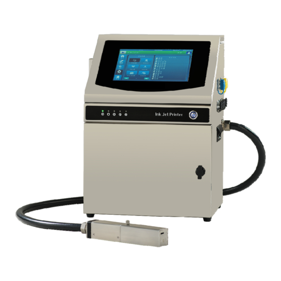
Page 7: Components
Components Printing system consists of Controller, Printhead and Umbilical tube which is flexible and strong enough to protect the ink tubes and wires inside it. Top View Power supply indicator Jetting on indicator Ready indicator Printing indicator Warning indicator Power switch Touch screen Unscrew two fixing screws M4x16, and open top cover, then could find Integrated main board and Core board. -
Page 8: Front View
Front View Rotate door lock counterclockwise to open the front door, then could find Ink tank, Solvent tank and Ink Mixer Tank. Ink mixer tank Ink tank Solvent tank Side View From side could find following connectors interface: Encoder interface, photocell interface, Serial interface, Printing output interface, Network interface, USB interface. -
Page 9: Equipment Setup
Gun body Charge electrode Detector Negative plate HV deflection plate Gutter Note Could find HV switch sensor on the interior surface of printhead cover. If “Printhead Warning” function enabled, HV will be shut off as soon as open printhead cover. Equipment Setup Printing System Component YourTJ560C printing system has been pre-assembled and tested for your convenience. -
Page 10: Installation And Setup Instructions
TJ560C printing system controller with umbilical cord All parts for printhead stand Photocell product sensor Power cord Installation tools User guide for TJ560C printing system Installation and Setup Instructions Remove the carton cover from the top, then find all parts for the printhead stand, and take them out. - Page 11 Remove the top white protection materials, and take the printer controller out of package, then mount the printing cabinet on a flat and secure surface. Make sure there is easy access to the operation panel. Leave sufficient room around the printer cabinet to be able to open the access panels.
- Page 12 Connect the photocell sensor to the socket on side-cabinet of printer before switching on it, otherwise the photocell sensor could not work normally. Note: photocell and encoder hot plug and play are not available in TJ560C printing system, please power off the printer before connecting the photocell sensor or encoder.
-
Page 13: Operation
Operation Status Indicator On top cover, could find five special designed status indicators: Power, Jetting on, Ready, Printing and Warning. Status Indicator Descriptions Power: Should be on after power on: Jetting on: Should be on after jetting on: Ready: Should be on when ink drop charging and phasing is ok: Printing:... -
Page 14: Menu Page
Device Debug Open File & File management Main Menu When TJ560C printing system is turned on, main menu will be displayed as following figure shown: Message Editing In main menu, click button, you will see “Message Editing” menu page as following figure... - Page 15 Note Block editing function are available in TJ560C printing system. After creating a block, you could double click it, the character`s color become red, then you could re-edit it; Click the other area out of this block, the character`s color become black, then this...
- Page 16 Message Editing Descriptions Click to create a new static text. Up to 40 blocks are available in TJ560C printing system, and up to 640 dot length for each block. Click this button, you will see following dialog: Font selection. Use the drop-down button to select font:...
- Page 17 Font size. Use the drop-down button to select the font size: Width(Bold) factor. Use the drop-down button to set the width (Bold) factor of the character:...
- Page 18 Character spacing. Use the drop-down button to set the character spacing: Click this button to insert a counter and open the counter settings page: Click this button to insert Time and Date:...
- Page 19 Multiple time formats can be set, and the time is the current time of the system. Click “Shift Setting” button, then could set the shift code, start and stop time of each shift. Four shifts can be set. Click this button to edit or insert logos The maximum height of the edited graphics is 32 points, and the maximum width is 320 points.
- Page 20 Click the “Open BMP” button to open the logo saved on the U disk or local disk. Click this button to insert barcode. Set the IP address of the external device, establish the connection between the external device and TJ560C, and then import the data to TJ560C.
- Page 21 Click this button to insert an external variable, which is stored on the U disk. Click this button to set print lines and font size. Click the button to copy fields . First, click on the block that needs to be copied, then click on the button, and the content is copied to the jet code machine cache.
-
Page 22: Printing Setting
Click this button to zoom in the selected fields. Click this button to zoom out on the selected fields. Click this button to save the edited file, which can be saved to local disk or U disk. Click this button to open the saved file, which was saved to local disk or U disk. - Page 24 Printing Parameters Descriptions Click this button, the screen on the right shows as follows: Use the drop-down button to select the right printing mode: Printing Mode Descriptions...
- Page 25 Photocell Triggers from Photocell. Encoder The Encoder mode is used when an encoder is plugged in to the printing system. Photocell auto Start or stop Auto Printing by photocell. Print the data saved in the U disk, Photocell usb data triggers by photocell.
- Page 26 16x16B For 16x16 dot, 2 rows message 16x16A For 16x16dot, 1 row message 12x12B For 12x12 dot, 2 rows message 12x12A For 12x12dot, 1 row message 9x7B For 9x7 dot, 2 rows message 9x7A For 9x7 dot, 1 row message 7x5D For 7x5 dot, 4 rows message 7x5C...
- Page 27 Use the drop-down button to select the desired print direction. Use the drop-down button to select the trigger mode of reverse print. Software trigger mode: The print direction controlled by the software, used with “Reverse repeat”. External Trigger mode: This is controlled by an external I/O signal.
- Page 28 Reverse repeat is how many it prints before the print direction changes, when the printer works in software trigger mode. Increasing or decreasing the Height will raise or lower the text height.100 is the maximum height. Setting Height too low may cause ink build-up on the gutter rube and affect print quality.
- Page 29 Switch printing messages through external I/O. Four DI signals can switch up to 16 messages Click this button, the screen on the right shows as follows: Triggers at the starting or falling edge of when the sensor “sees” the product. Sets number of prints per trigger.
-
Page 30: System Setting
Sets delay time between prints “Meter Counting Parameter” is used to define how many encoder pulses there are between prints when in the repeat mode. Set the “ F.Div.Coefficient” to dictate message length. The higher the value, the longge the message will print. Default encoder value is “0”. - Page 31 System Setting Descriptions Increases and decreases the ink stream pressure.
- Page 32 Add Make-up to the mixing tank to decrease viscosity. Increase or decrease the ink drop break point. The highe the value, the faster the break will be. Turn the heater ON or OFF. Turn the High Voltage On or Off.
- Page 33 The “Alarm settings” icon will open the alarm settings window. In the Alarm Settings window, place a button you would like to monitor. Stopped alarms will not be recorded in the alarm log. If the “Gutter” is started the system will stop jetting after a few seconds pass without the gutter receiving ink.
- Page 34 Switching languages through the follow window: Occasionally, software and/or firmware updates will become avalible from KeSiHui. Software and Printer System Firmware can be updated from U disk. Set network parameters through the following window:...
- Page 35 To set level 1 and level 2 password. Level 2 password has higher protection level. Select the “Date & Time” icon to change the date and time in the printer Selecting the “System Info” icon will display important information for the currently selected printer.
-
Page 36: Ink System
Ink System The “Ink System” window contains keys for stopping/starting and cleaning the ink system. It also contains a “Status” section that monitors the condition of the ink system. Select the “Ink System” icon to open the Ink Operation window. -
Page 37: Maintenance
Ink System Descriptions Start the ink system jetting. Stop the ink system jetting. Perform the Cleanjet cleaning cycle when jetting starts. Selecting “Purge” will cause a light suction for about 20 seconds at the nozzle face. This is used when spraying cleaner externally onto the nozzle so the cleaning fluid can be drawn back into the Gunbody. - Page 38 and the ink itself. It also contains a “Status” section that monitors the ink system. Ink System Descriptions Printer will detect and display the current viscosity. Will add a small amount of make-up to the reservoir. Performing this function will slightly lower viscosity. Runs a cleaning cycle through the Gunbody.
-
Page 39: Device Debug
This will drain the mixing tank. Follow the on-screen prompts to perform drain the mixing tank. This will flush the system for a short-term shutdown. Follow the on-screen prompts to perform a short-term shutdown. This will drain the mixing tank and flush the entire printer with make-up. - Page 40 Device Debug Descriptions Click this button,the right window will display the device test window. Device test window is generally used by service and engineering personnel. Device test window is only available if the hydraulics (jet) are shut down/off. A/C power must be on.
- Page 41 Click this button, the right window will display the ink level in the mixing tank. Click this button, the right window will display the details of the filter. Click this button, the right window will display the Screen Setting window.
-
Page 42: Warning Log
Click this button to restore factory settings (may be password protected from operator). Warning log Selecting the “Alarm event” icon will display a list of tripped system alarms. -
Page 43: File Management
File Management In main menu, click button, you will see Load file menu as following figure shows:... -
Page 44: Maintenance
Maintenance Daily Maintenance Turn Off Daily At the end of working day, it’s recommended that you select “Clean & Stop” in Ink System menu page to stop the printer. The printer will clean the gunbody and nozzle automatically while jetting off. Switch off the power supply after jetting off. -
Page 45: Checking The Level Of Ink Tank And Solvent Tank
Checking the level of Ink tank and Solvent tank If no remaining ink and solvent in bottles, and remaining percentage become 0%, it will cause printer shut down suddenly while working, so it recommended that customers change ink and solvent bottle timely when remaining percentage become 0%. If ink remaining percentage becomes 0%, and printer still jetting on, then it could continue working for 18 hours. -
Page 46: Ink Drop Break-Off Adjustment
1. Loosen fixing screw. 2. Adjust ink streamline position. 3. Fasten gunbody. Ink Drop Break-off Adjustment The Ink Drop Break-off must be adjusted properly to obtain good quality printing. The Ink Drop Break-off Point should be in the middle of the Charge Electrode Tunnel. Ink Drop Break-off is related to the following conditions: ... -
Page 47: Shut Down Over One Month
Note: Whenever working with fluids or inks, be sure to wear gloves, safety glasses and protective clothing. Open the ink outlet at the back of ink mixer tank, put the by-pass tube into an empty bottle, and run[Maintenance] →[Tubes Emptying] till no more ink comes out from by-pass tube, discharge volume of ink is 600ml, taking about 5 minutes. -
Page 48: Changing Filters
Note: Operating conditions can vary. Excessive heat, dust, and humidity could all affect filter life. Changing Filters Main Filter Changing As shown on the above drawing, when filter time below 200 hours, “Filter assembly remaining cycling time less than 200 hours, please replace it timely!” warning will be shown on screen. - Page 49 Remove the old main filter. Place the new filter in the mounting position. Notice: Please ensure to install the four O rings 9.6x1.8. Close the back door. Plug the printer into a properly wired and grounded power source. Turn on the power and follow the normal start up procedure. Ink Feeding Filter, Return Filter and Cleaning Filter The procedure for changing these ink filters is similar.
-
Page 50: Cleaning Or Changing Fan Filters
Note: Make sure the filter is in the proper orientation. Tip! Take a few moments and carefully inspect the fluid lines. Make sure they are in good condition with no cracks or leaks. Make sure the ends have neat square cuts and will seat well in the fittings. -
Page 51: Printhead Cover Is Open" Warning
Overflow” will not be displayed in [Warning Log] anymore. Then start jetting on for 15 minutes to check ink viscosity value (should be “setting viscosity value”±10). “Printhead cover is open” warning If printhead cover warning function enabled, when open printhead cover while printing, this warning will occur, also warning indicator will light on. -
Page 52: Ink Bottle Chip Fault" Warning
“Ink bottle chip fault” warning When following fault occurs, warnings will be displayed on screen. Also “Ink bottle chip fault” will be displayed in [Warning Log]. 1. “Ink bottle not detected” When ink bottle not fitted well in position or not fitted, warning “Ink bottle not detected” will be displayed on screen, also warning indicator will light on. -
Page 53: Solvent Bottle Chip Fault" Warning
“Solvent bottle chip fault” warning When following fault occurs, warnings will be displayed on screen. Also “Solvent Bottle Chip Fault” will be displayed in → [Warning Log]. 1. “Solvent bottle not detected” When Solvent Bottle not fitted well in position or not fitted, warning “Solvent Bottle Not Detected” will be displayed on screen, also warning indicator will light on. -
Page 54: Solvent Shortage" Warning
clearing the fault. Also “Ink shortage” will be displayed in → [Warning Log]. “Solvent shortage” warning When solvent is insufficient and sensor of Solvent Tank could not detect solvent, “Solvent shortage” will be displayed on screen and warning indicator will light on, printer will continue working for 3 hours then execute jetting off procedure automatically. -
Page 55: Troubleshooting
Photocell can’t trigger printing after connected to the printer. Possible Solutions: Check the printing mode. If this doesn’t help, continue on. Jetting off and power off, connect the photocell again. Note: Photocell Hot-Plug is not available in TJ560C printing system.
Need help?
Do you have a question about the TJ560C and is the answer not in the manual?
Questions and answers