Subscribe to Our Youtube Channel
Summary of Contents for SENSECAP S-Soil MT-02
- Page 1 User Manual Soil Moisture & Temperature Sensor User Manual Product Model: S-Soil MT-02 Version: V2.0 1 / 15 ©2008-2020 Seeed Technology Co., Ltd. All rights reserved. solution.seeedstudio.com...
-
Page 2: Table Of Contents
User Manual Contents Introduction ............................3 Specifications ............................4 Wiring ..............................5 Installation ............................. 6 Modbus Communication Protocol ......................7 Serial communication parameters ..................... 8 Modbus Register ........................9 Detail of Modbus Register ......................11 CRC16 Validation and Sample Code ..................14 2 / 15 ©2008-2020 Seeed Technology Co., Ltd. -
Page 3: Introduction
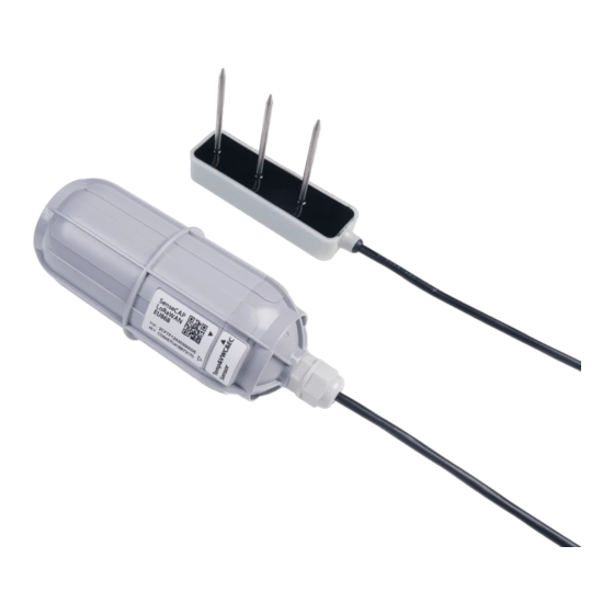
User Manual 1 Introduction The S-Soil MT-02 soil moisture & temperature sensor is provided with high accurate and high sensitive. By measuring the dielectric constant of the reaction of soil, soil direct stable real moisture content. This S- SOIL MT-02 soil moisture & temperature sensor can measure the volume of soil moisture. the soil moisture measurement method is in line with international standards at present. -
Page 4: Specifications
Soil Moisture Range From completely dry to fully saturated (from 0% to 100% of saturation) Accuracy ±3% (0~53%); ±5% (53~100%) Resolution General Parameters Product Model S-Soil MT-02 Interface RS-485 0-2V voltage Protocol MODBUS-RTU RS485 Power Supply 3.6 ~ 30V DC 3.9 ~ 30V DC... -
Page 5: Wiring
User Manual 3 Wiring Yellow RS485+/A/T+ White RS485-/B/T- VCC+, power supply Black VCC-, power ground Blue Temperature Output Brown Moisture Output Green SET, V+ (power) when boot module into the "setting mode". Not connected or connected with the GND when boot into "mode of operation". Module configuration parameters such as Modbus address, baud rate, parity, communication protocol is composed of module inside the EEPROM (power down storage device stores). -
Page 6: Installation
User Manual 4 Installation Rapid measurement method: the selected measurement locations, the right to avoid the rocks, to ensure that the needle will not touch the stones like hard object, according to the required depth of cut open the surface soil, maintain the tightness degree of the original soil below the sensor body, clenched vertically inserted into the soil, can not be inserted before and after shaking, ensure the close contact with the soil. -
Page 7: Modbus Communication Protocol
User Manual 5 Output Model The parameter range conversion relation Output voltage 0-2V corresponding Temperature =60.0* voltage -40. If the temperature of -40- measured voltage is 1.5V, the temperature of 80 ℃ =60.0*1.5-40=50.00 ℃. volumetric water volumetric moisture content=0.15*voltage . content corresponding If the measured voltage is 1.5V, the 0-30%... -
Page 8: Serial Communication Parameters
User Manual 6 Modbus Communication Protocol 6.1 Serial communication parameters Modbus is a serial communication protocol, Modicon programmable logic controller (PLC) for the use of published. It has become the industry standard communication protocols, and is now quite common connection between industrial electronic equipment. Modbus has extensive application in the industrial field. -
Page 9: Modbus Register
User Manual 6.2 Modbus Register Modbus Register address (HEX) Parameter Parameter Type Function Range of Parameters and instructions default Channel 0 Number -4000-8000 Divided by 100 to obtain the actual Temperature 0x0000 INT16,read only temperature value. temperature measurement model the readout value is always 0. - Page 10 User Manual 2:Odd parity UINT16,Read 1:8 data data bits 0x0204 3/6/16 and write 1:8 data bits bits UINT16,Read Stop bits 0x0205 3/6/16 0:1 stop bits stop bits and write 1:2 stop bits 0-255 The host request command is received UINT16,Read Response delay 0x0206 3/6/16...
-
Page 11: Detail Of Modbus Register
User Manual 6.3 Detail of Modbus Register Soil Temperature parameter range -4000-8000 Default: none parameter storage none Significance: the measured value of the temperature, negative for complement representation. Example: if the return value is 0702H (16 m, the original code), the first byte byte second byte 07H, low byte is 02H, then the temperature measurement value of (07H*256+02H) /100=17.94 C. - Page 12 User Manual Modbus Address parameter range 0-255 Default:1 or 17 parameter storage Immediate memory The Modbus address, can be set to 0-255. When the module external address code switch is set to address 0, use this register contents as the slave address. After setting the need to power on or use the RST command to restart module, make this address in force.
- Page 13 User Manual Response Delay parameter range 0-255 Default:0 parameter storage Immediate memory Serial communication delay in response to a user in the following cases: when the host sends a request command module, delay (RESPONSEDELAY*10) ms, then the response data is returned to the host computer.
-
Page 14: Crc16 Validation And Sample Code
User Manual 6.4 CRC16 Validation and Sample Code For example: 0x0000H-0x0001H read registers, measuring temperature, volumetric water content values Request: 01 03 00 00 00 02 C4 0B (8 bytes) Device address 1 byte 0x01 Function number 2 bytes 0x03 starting register 2 bytes... - Page 15 User Manual crc ^= c; for(j = 0;j < 8; j ++) if (crc & 0x0001) crc>>=1; crc^=0xA001; else crc>>=1; return(crc); To get results back to 0 then the verification is successful, if the validation fails to return to a non-zero value.

Need help?
Do you have a question about the S-Soil MT-02 and is the answer not in the manual?
Questions and answers