Table of Contents
Advertisement
Advertisement
Table of Contents

Summary of Contents for Hanwell 4000 Series
- Page 1 IM5990 4000 Series Sensor Units User Guide hanwell.com...
- Page 2 Intentionally Left Blank...
- Page 3 4000 Series Sensor Units User Guide Document History Document Number: IM5990 Issue Issue Date Changes 1 June 2018 First Issue 7 November 2018 Additions to Section 2.4 Compliance Addition of Section 3.1 - Connecting Sensor 13 November 2019 Units to External Probes...
-
Page 4: Table Of Contents
Setting up 4000 Series Sensor Units ................7 Connecting Sensor Units to an External Probe ................ 7 Testing the Sensor Unit ........................8 Entering a 4000 Series Sensor Unit’s Calibration Settings into EMS ......... 8 3.3.1 Setting Alarms ..........................15 Synchronising Sensor Units ...................... -
Page 5: Introduction
Durable Units) from Hanwell Solutions Ltd for use in conjunction with the EMS application. • Durable Units (-DU) function in exactly the same way as other 4000 Series Sensor Units, but have a higher IP Rating. It also details the additional functions, such as Calibration. -
Page 6: The 4000 Series Sensor Unit
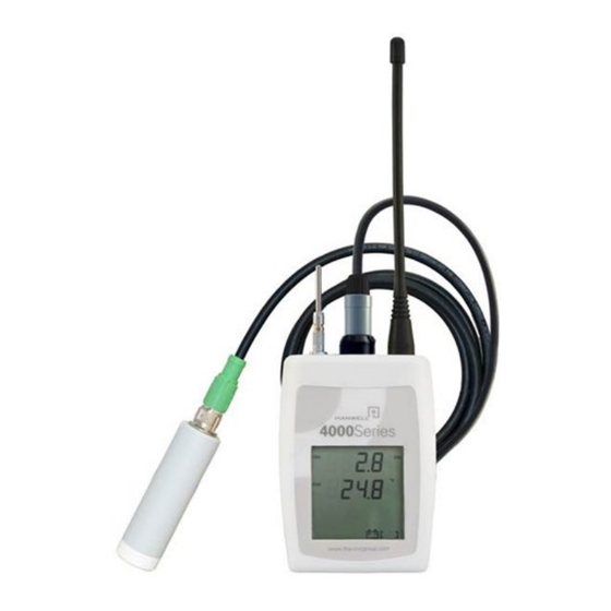
4000 Series Sensor Units User Guide 2 The 4000 Series Sensor Unit The illustrations below represent typical 4000 Series Sensor Units fitted with probes. Figure 1 – Typical 4000 Sensor Units Durable Unit Figure 2 – Typical 4000 Series Sensor Unit - Schematic Note: The actual design will vary depending on the probes you have installed. -
Page 7: Sensor Unit Battery
• To mount a 4000 Series Sensor Unit on the bracket, line up the slots on the back of the Unit with the tabs on the bracket and click the Unit into place. -
Page 8: Start-Up Messages
Hardware Reset by shorting the pads visible beside the battery. 2.6 Cleaning the Sensor Unit The 4000 Series Sensor Units are cased in ABS plastic and can be cleaned using a damp, non- abrasive cloth. -
Page 9: Setting Up 4000 Series Sensor Units
4000 Series Sensor Units User Guide 3 Setting up 4000 Series Sensor Units For information on entering 4000 Series Sensor Units’ details into EMS, please refer to the EMS Online User Guide, in particular the section System Configuration - Sensors: http://www.help.emsprocloud.com/index.html?system-configuration-sensors.html •... -
Page 10: Testing The Sensor Unit
4000 Series Sensor Units User Guide 3.2 Testing the Sensor Unit Before putting a 4000 Series Sensor Unit in its intended monitoring location, we recommend testing its operation after entering its details into EMS: • Connect a Radio Testing Dongle (Code: Y058), if you have one, to the USB socket of the Sensor Unit to speed the test. - Page 11 4000 Series Sensor Units User Guide Figure 5 • By default, the Edit Mode window for the Zone at the top of the left-hand menu is displayed. • To display another Zone's Edit Mode window, click on the entry for the required Zone in the left-hand menu.
- Page 12 In the left-hand list, click on the required 4000 Series Sensor Unit’s icon: In the table in the Zone's Edit Mode window, click on the required 4000 Series Sensor Unit’s name in the Sensor Name column. See Figure 9 below: hanwell.com...
- Page 13 4000 Series Sensor Units User Guide Figure 9 • The Edit Mode window for the selected 4000 Series Sensor Unit is displayed. See Figure 10 below: hanwell.com IM5990-8 Page 11 of 23...
- Page 14 4000 Series Sensor Units User Guide Figure 10 Click the on the Calibration field to expand the Calibration pane for the selected 4000 Series Sensor Unit. • The Calibration pane will display a separate tab for each channel/probe associated with the selected 4000 Series Sensor Unit.
- Page 15 4000 Series Sensor Units User Guide Figure 11 Click on each tab representing the sensor(s)/probe(s) to be calibrated and: Enter the date that the next Calibration is due into the Next Calibration Due Date field, in the format: YYYY-MM-DD ∗...
- Page 16 If the Update has been successful, you will be returned to Edit Mode window and the following message will be displayed. See example in Figure 12 below: Figure 12 Repeat Steps 2 -5 for all required 4000 Series Sensor Units. hanwell.com Page 14 of 23 IM5990-8...
-
Page 17: Setting Alarms
4000 Series Sensor Units User Guide Note: Should you wish to carry out your own calibration of a sensor/probe, please refer to both the EMS Online User Guide: http://www.help.emsprocloud.com/index.html?calibration-management-tools.html and the following links which are also listed on the Box Insert: http://pd.hanwell.com/Cal-linear-sensor.xls... -
Page 18: Synchronising Sensor Units
4000 Series Sensor Units User Guide 3.4 Synchronising Sensor Units The Synchronise process takes data from a connected USB device and updates its Serial Number, and Calibration settings in the EMS Database; as well as setting the Physical Transmit ID of the device from the EMS Database. - Page 19 4000 Series Sensor Units User Guide Figure 13 Right click on the selected Sensor Unit’s entry and select Sync Selected Sensor from the displayed menu. See Figure 14 below: Figure 14 The EMS Synchronise USB Sensor Vx.x window is displayed. See Figure 15 below: hanwell.com...
- Page 20 4000 Series Sensor Units User Guide Figure 15 Note: The Sensor Unit selected must match the physical device or the program will not complete. Select the required Transmit (TX) interval from the Transmit interval drop-down list (60 seconds is recommended for Calibration).
-
Page 21: Alarms On Sensor Lcd Display
4000 Series Sensor Units User Guide 3.4.1 Alarms on Sensor LCD Display Sensors with LCD displays can be configured to show an alarm bell symbol on the display when the High High or Low Low alarm threshold is exceeded, using the process described here. -
Page 22: Merging Collected Data
EMS Online User Guide: http://www.help.emsprocloud.com/index.html?EMS-Remote-Management-Tool.html From the displayed drop-down menu, select Merge Selected Sensor. See Figure 18 below: Figure 18 • The Hanwell 4000 series logger download window is displayed. See Figure 19 below: hanwell.com Page 20 of 23 IM5990-8... - Page 23 4000 Series Sensor Units User Guide Figure 19 Click on the Download button. • The Save Data button becomes active and ‘Download complete’ is displayed in the bottom left-hand corner of the window when the Download is complete. See Figure 20...
- Page 24 4000 Series Sensor Units User Guide Figure 21 • When the Waiting for Task window disappears with no error messages displayed, the data from the Sensor Unit’s memory has been successfully merged with the E Database. The Merge Collected Data process is now complete and the Data filing complete Information window is displayed.
-
Page 25: Contact Hanwell Solutions
Tel: 01462 688070 Email: sales.hanwell@ellab.com Web: www.hanwell.com For Technical Support: Tel: 01462 688 078 Email: support.hanwell@ellab.com EU & Overseas Customers: Please contact your local Hanwell Distributor. A list of distributors is available at: https://hanwell.com/distributors/ hanwell.com IM5990-8 Page 23 of 23...
Need help?
Do you have a question about the 4000 Series and is the answer not in the manual?
Questions and answers