
Summary of Contents for Tetra TMR880i
- Page 1 INSTALLATION GUIDE FOR EADS TMR880i TETRA MOBILE RADIO AND CUR-3 CONTROL UNIT XXXJ4096-EN-0.1 1 (61)
- Page 2 Copyright © 2010 EADS Secure Networks Oy. All rights reserved. All particulars included in the materials, including but not limited to computer programs and documentation, were provided by EADS Secure Networks Oy exclusively for your information. The materials are subject to copyright and any copying, distribution, modification, reproduction, adaption and translation in part or in its entirety is strictly prohibited - without the prior written permission of EADS Secure Networks Oy.
-
Page 3: Table Of Contents
Contents Contents General information ................5 Terminology ................... 5 Contact ....................5 EADS TMR880i Technical Specifications ........... 6 Sales packages for TMR880i ............... 8 Radio sales package................8 Control Unit CUR-3 sales package............8 Basic configuration................. 8 Connectors and PIN-layouts ............. 11 Speaker microphone cable and connector ........... - Page 4 7.1.2 Front panel cable for speaker microphone (MPR-1) ......40 7.1.3 Swivel (HHR-1) Assembly ..............42 TMR880i installation by using an installation plate (9500318) ....44 7.2.1 Installation plate ................... 44 CUR-3 installation into DIN-slot by using the DIN-slot installation set ..................46 7.3.1...
-
Page 5: General Information
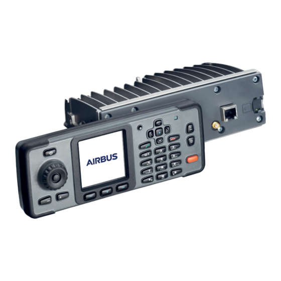
General information General information The EADS TETRA TMR880i mobile radio conforms to the ETSI standards for compatible digital TETRA networks. It has been targeted to meet the demanding communications requirements of professional mobile radio users, from voice communication to messaging and data transmission. -
Page 6: Eads Tmr880I Technical Specifications
EADS TMR880i Technical Specifications The EADS TMR880i TETRA mobile radio fulfils the following specifications for TETRA radio equipment in the temperature range – ο 20 to +55 C : ETS 300 392-2 Voice and Data Air Interface, ETS 300 394 Voice and Data Conformance testing and ETS 300 395 V + D Air Interface. - Page 7 EADS TMR880i Technical Specifications Dimensions & weight Control Unit Length x Height 190 x 72 mm Thickness 26 mm (36 mm with rotary switch) Weight 240 g Radio unit L x H x W 182 x 60 x 125 mm...
-
Page 8: Sales Packages For Tmr880I
Sales packages for TMR880i The TMR880i has two separate sales packages. A radio package is a customer specific and CUR-3 Control Unit sales package is generic for all customers. The CUR-3 Control Unit is available in 5 different keymat variants: Latin, Arabic, Chinese, Korean and Greek. - Page 9 Sales packages for TMR880i HFR-1 HSU-1T TETRA antenna Flashing Parametring NMEA output * Not included in the sales package. ** May be included in the sales package. Please check from your sales contacts. *** EXT line can be used to connect external emergency button into the radio unit via system cable.
- Page 10 connected to corresponding IGN line in vehicles power switch. If IGN line is connected and vehicle is switched on, power is also supplied to radio via IGN line. Once vehicle is switched off, there is user request to continue radio operation; otherwise radio will also be switched off as IGN line gets down.
-
Page 11: Connectors And Pin-Layouts
Connectors and PIN-layouts Connectors and PIN-layouts Connectors in the back-front 1. System Connector (§4.2 ) .2 Control Unit Interface Connector (§4.3 ) Installation cables from 0.75m to 10m Overall diameter: 8.3±0.2 mm Minimum bending radius: 5 x D 3. Auxiliary Accessory Connector (I/O Pins) (§4.4 ) Antenna Connector (§0) Warning: Both Control unit and auxillary connectors are DB-26 female. - Page 12 Connectors in the front panel GPS Antenna Connector (§4.6 ) External Smart Card Connector (§4.5 ) Connectors in CUR-3 Speaker microphone connector (§4.1) Helmet cable connector (§5 ) Overall diameter: 5.9±0.2 mm Minimum bending radius: 5 x D See Chapters 7.1.1 and 7.1.2 for placements of speaker microphone and helmet cable connectors.
-
Page 13: 4.1 Speaker Microphone Cable And Connector
Connectors and PIN-layouts 4.1 Speaker microphone cable and connector Speaker microphone cable is used to provide connection from Control Unit (CUR-3) to the Speaker microphone MPR-1. The cable is an accessory which can be connected permanently to a PWB connector of the CUR-3 through opening in the back cover. -
Page 14: System Connector
Signal Parameter IN/OUT Min. Typ. Max. Unit Notes SPM_SPK+ Speaker-mic LSP+ SPM-MIC- Speaker-mic microphone Data Data System Connector The system connector is a male 26-pin high density D connector which makes all the main connections. These include the power feed, HF equipment, Helmet connection, and data interface. - Page 15 Connectors and PIN-layouts Technical data: Signal Parameter Min. Typ. Max. Unit Notes 1, 2, 3 CARBAT+ The external supply 10.8 13.2 15.6 voltage EXT_EMERGENCY External Emergency Signal PTT button Stand by. State change by ground. +10V Supply voltage for OUT 9.5 10.55 the data cable DLR- mADC...
-
Page 16: Control Unit Interface Connector
The CUR-3 connector provides an interface for the external control unit. The connector is a female 26 pin high density D connector. The display data bus parallel to TMR880i display controls and serial data interface are converted to RS-485 level. The connector includes also an audio interface and the voltages supply for the control unit. - Page 17 RS-485 output voltage SCLK- Display Serial clock, Driver common mode RS-485 output voltage CU_TXD+ Ext. CU control data Driver common mode from TMR880i, output voltage RS-485 CU_TXD- Ext. CU control data Driver common mode fromTMR880i, output voltage RS-485 data CU_RXD+ Ext.
-
Page 18: Auxiliary Accessory Connector
Signal Parameter IN/OUT Min. Typ. Max. Unit Notes CU_REG_CTRL Ext. CU voltage Logic low regulator control Logic high 18,19 GND EXT_MIC+ Ext. CU microphone, Vrms Signal level Connected to HS mic input using an analogue MUX EXT_MIC- Ext. CU microphone ground EAR+ Audio to Ext. - Page 19 Connectors and PIN-layouts Technical data: Signal Parameter IN/OUT Min. Typ. Max. Unit Notes 1-9, GEN_IO Programmable I/O IN/OUT -0.5 Low level input High level input 11-17 High level output Maximum 8 mA EXT_ALARM External alarm control Open collector/ drain output Maximum 0.5 A 18, 19 HS_MIC+...
-
Page 20: External Smart Card Connector
External Smart Card Connector This connector offers the interface for an external smart card reader (DD-5) through an RJ45 connector. Face view of RJ45 smart card reader (radio part): The length of external smart card reader cable is app. 1800 mm. Active GPS antenna connector This connector provides the interface for the active GPS antenna with output supply 5V, 30mA through an SMA (female) connector. -
Page 21: Tetra Antenna Connector
Connectors and PIN-layouts TETRA antenna connector This connector provides the interface for the TETRA RF antenna (50 ohm) through a TNC (female) connector. Face view of TNC TETRA antenna (radio part): Smart card connector This connector provides the interface for a smart card or SIM card. -
Page 22: Helmet Cable Installation
Helmet cable installation Introduction Helmet installation cable is used to provide connection from Control Unit (CUR-3) to the motorbike installation set. The cable is an accessory which can be connected permanently to a PWB connector of the CUR-3 through opening in the back cover. The opening is sealed and provided by a cable clamp. -
Page 23: Detailed Description Of The Helmet Interface
Helmet cable installation Customer spesific accessories X1 Helmet Cable Connector HELMET_MIC+ Helmet microphone HELMET_MIC- HELMET_SPK+ Helmet Twisted pair speaker HELMET_SPK- Push-to-talk switch Twisted pair MC_PTT HELMET_SWITCH 9 Helmet Twisted pair switch SPKMIC_MUTE Speakermic Twisted pair mute switch Figure 1 Circuit diagram of helmet cable Detailed description of the helmet interface 5.3.1 Microphone Input Interface... - Page 24 Figure 2 Helmet Cable Microphone Input Flowchart 5.3.1.1 Electrical Specifications Table 1 Microphone Input Electrical Specifications Parameter Min. Typ. Max. Unit Notes Input impedance Biasing voltage Biasing voltage level to 2k microphone impedance. Input level Maximum differential peak to peak input voltage level to the microphone input.
-
Page 25: Speaker Output Interface
Helmet cable installation 5.3.1.3 Selection Of The Electret Microphone Capsule Be sure that the selected electret microphone capsule is RF noise- resistant type and it fulfils 89 / 336 / EEC EMC directive, because most of the electret microphones are very sensitive for the RF-noise. HELMET_MIC+ and HELMET_MIC- inputs are filtered against RF- noise, but there is no possibility to filter audio frequency noise, which has been indicated from the RF-signal in microphone capsule. -
Page 26: Control Signals
5.3.2.1 Electrical Specifications Table 2 Speaker Output Electrical Specifications Parameter Min. Typ. Max. Unit Notes Load Min. load impedance, which can Impedance be connected between speaker outputs, without producing audible distortion. * Output power , THD = 0.5%, f = 1kHz Output level Max. -
Page 27: Technical Specification
Helmet cable installation Table 3 Control Signals Control Signal Contact type Function MC_PTT OFF-ON External push to talk button for semi- duplex calls. (ON) = momentary contacts. Switch is closed when it is pressed and open when released. Contacts return automatically to OFF position HELMET_SWITCH OFF-ON... - Page 28 Pin Line Symbol Cable Cable Pair with line (pin) Min. Typ. Max. Unit Notes colour thickness HELMET_MIC+ line HELMET_SPK+ OUT White AWG26 HELMET_SPK- (6) HELMET_SPK- OUT Brown AWG26 HELMET_SPK- (5) Green AWG26 MC_PTT (8) MC_PTT Yellow AWG26 GND (7) Logic low Logic high HELMET_SWIT Grey...
-
Page 29: Accessories
CA-104 T0730627 Helmet cable CA-106 T0730632 GPS antenna AN-5 HR7773AA Combined TETRA/GPS antenna 380-430MHz AN-6 HR7774AA Fixed mount TETRA antenna 380-430 MHz AN-7 HR7775AA Magnet TETRA antenna 380-430MHz AN-9 HR7816AA Smart card reader DD-5 T0632189 Combined TETRA/GPS antenna 806-870MHz AN-12... -
Page 30: Handset (Hsu-1T)
Please check the availability from your local distributor. Please check your warranty terms before connecting other than those EADS own accessories. TMR880i can be assembled in a desktop kit. The installation manual of the desktop kit is available as a separate document. Handset (HSU-1T) 30 (61) Version 4.3... -
Page 31: Data Cable (Dlr-3T)
Accessories Data Cable (DLR-3T) Antennas (AN-5, AN-6, AN-7, AN-9, AN-12) AN-5: Magnet GPS antenna Version 4.3 31 (61) - Page 32 AN-6: Combined TETRA and GPS antenna 380-430MHz AN-12: Combined TETRA and GPS antenna 806-870MHz + 2 cables + FME/TNC connector AN-7: Fixed mount TETRA antenna 380-430MHz + cable + FME/TNC connector 32 (61) Version 4.3...
-
Page 33: Cur-3 Installation Cables (Ca-103, Ca-104, Ca-108, Ca-116)
Accessories AN-9: Magnet TETRA antenna 380-430MHz + FME/TNC connector Please check from your sales contacts for other antennas. CUR-3 installation Cables (CA-103, CA-104, CA- 108, CA-116) Version 4.3 33 (61) -
Page 34: Power Supply (Acr-1E, Acr-1U, Acr-1X )
Power supply (ACR-1E, ACR-1U, ACR-1X ) Speaker Microphone (MPR-1) MPR-1 is optionally included in CUR-3 sales package. Please check from your sales contact. 34 (61) Version 4.3... -
Page 35: Swivel Mount (Hhr-1)
Accessories Swivel mount (HHR-1) External Smart Card Reader (DD-5) Note: Smart card is not included in DD-5 package. Please check the availability of smart cards from your sales contacts. Version 4.3 35 (61) -
Page 36: Installation Plate (9500318)
Other parts 6.8.1 Installation plate (9500318) 6.8.2 Installation cover (9452555) 6.8.3 DIN installation set (T0087632) DIN installation set consists of DIN-slot installation bracket and adapter. Adapter is mounted inside the DIN-slot installation bracket and will be locked with solenoid. 36 (61) Version 4.3... -
Page 37: Extra Connector (Ht8418Aa)
Accessories DIN-slot installation bracket DIN-slot installation adapter 6.8.4 Extra connector (HT8418AA) Version 4.3 37 (61) -
Page 38: Fuse 5A 125° C Rated (Pk1705A)
6.8.5 Fuse 5A 125° C rated (PK1705A) 38 (61) Version 4.3... -
Page 39: Considerations For Tmr880I Installation
Considerations for TMR880i installation Considerations for TMR880i installation Please read these installation guidelines carefully through and follow them faithfully. EADS cannot guarantee the targeted functionality if EADS´s installation instructions are not properly followed. Assembly instructions for CUR-3 7.1.1 Installation cable and optional helmet cable assembly... -
Page 40: Front Panel Cable For Speaker Microphone (Mpr-1)
Figure 4 CA-103/CA-104/CA-108/CA-116 Installation Cable and CA-106 Helmet Cable assembly 7.1.2 Front panel cable for speaker microphone (MPR-1) The connector for the speaker microphone is Hirose HR30-7J-12PC. The connection to the circuit board is implemented using wires to the SMK CGP4512-0101 connector. The Hirose connector is used for the speaker microphone. - Page 41 Considerations for TMR880i installation Figure 5 Fastened cable cover Figure 6 Speaker microphone connector Version 4.3 41 (61)
-
Page 42: Swivel (Hhr-1) Assembly
7.1.3 Swivel (HHR-1) Assembly Figure 7 Complete Swivel (HHR-1) Figure 8 Swivel fastening (Fixed Mounting kit, MKE-1BK) 42 (61) Version 4.3... - Page 43 Considerations for TMR880i installation Figure 9 Fastened Swivel Fastened Swivel Figure 10 Version 4.3 43 (61)
-
Page 44: Tmr880I Installation By Using An Installation Plate (9500318)
There are 12 holes in the bottom of the Installation plate for fixing the bracket onto a base, panel etc. Fix the TMR880i radio unit to the Installation plate with two of the stainless steel screws provided in the screw bag. The maximum inclination for the radio unit is approx. - Page 45 Installation Cover’s cooling fins. The above picture shows the attached tapes. When installing the installation cover on the TMR880i radio unit, press the spot shown above to ensure the cover is positioned at the proper height with respect to the Front Panel.
-
Page 46: Cur-3 Installation Into Din-Slot By Using The Din-Slot Installation Set
CUR-3 installation into DIN-slot by using the DIN- slot installation set 7.3.1 Preparations for DIN-slot installation bracket Assembly DIN-slot installation bracket (9537050) Notice before installation! Electrical or manual unlocking system must be in use before inserting the DIN-slot installation adapter into the DIN-slot installation bracket. Please read these installation guidelines carefully through and follow them faithfully. - Page 47 (9537050) and position it as desired. (Pull cord is not included in the Sales Package). There is also a mounting hole for screw fastening (M4) at the back panel of the TMR880i radio unit. The fixing tabs of the assembly DIN-slot installation bracket can be bent.
-
Page 48: Preparations For Din-Slot Installation Adapter
7.3.2 Preparations for DIN-slot installation adapter Fasten the swivel (HHR-1) into the DIN-slot installation adapter with screws. DIN-slot installation adapter is mounted inside the DIN-slot installation bracket and will be locked with solenoid. 48 (61) Version 4.3... -
Page 49: Attaching Cur-3 Into Din-Slot Installation Set
Considerations for TMR880i installation 7.3.3 Attaching CUR-3 into DIN-slot installation set Attach the swivel (HHR-4) into the CUR-3 and fasten CUR-3 into the swivel as described in Chapter 7.1.3 . Version 4.3 49 (61) -
Page 50: Instructions For Shortening The Installation Cable (Ca-103, Ca-104, Ca-108)
Instructions for shortening the installation cable (CA-103, CA-104, CA-108) It is possible to shorten the installation cables CA-103 and CA-104 and CA-108 by using an extra connector. Those modifications have to be made by professional to guarantee the functionality and performances of the product with the modified cable. - Page 51 Considerations for TMR880i installation The modification consists of cutting the cable and rewiring the connector on the radio side ( High density 26 AMP plug (X1)) using a new high density 26 AMP plug. Appearance of Installation Cable Figure 11...
- Page 52 The X1 connector cover which has to be assembled according to Dir. A in Figure 12. The connection on X1 is described in the following circuit diagram and table. Connections, pin numbers, cable colours are listed in the following table. Signal IN/OUT Cable Color Cable...
-
Page 53: Power Distribution
Considerations for TMR880i installation Signal IN/OUT Cable Color Cable Twisted with line Unit Notes thickness (pin) CU_TXD+ Purple/Red AWG26 CU_TXD- (9) Driver common mode output voltage CU_TXD- Purple/Black AWG26 CU_TXD+ (8) Driver common mode output voltage Green/Red AWG26 /LCD_RES (1) - Page 54 mains voltage of other than 12 volts. This minimises the risk of disturbances from or to the radio unit, as well as guaranteeing loss- free power distribution. Grounding cable is connected to the car chassis, with as short a lead as possible (not directly from the negative pole of the battery!).
-
Page 55: System Cable
Considerations for TMR880i installation System cable Version 4.3 55 (61) - Page 56 System cable connections: X1, System X2, Connections for data and handset Connector as in DTC-1 adapter HD26 X3, HF_MIC HFR-1/ 3.5 mm stereo jack X4, HF Speaker HFS-10 / Molex X5, GPS NMEA Output / 9-Pin Sub D X6 and X7, Power Supply / Flat connector + Fuse X8, IGNITION / Flat connector + Fuse X9, EXT_EMERGENCY PTT/ Flat...
- Page 57 Considerations for TMR880i installation Connector(s) Name Note High Density 26 AMP plug AMP 1658682-1 X100 (X2) 10-pin modular connector in X2 (DTC-1) SS-641010-NF-K1 (Stewart) X200 (X2) 10-pin modular connector in X2 (DTC-1) SS-641010-NF-K2 (Stewart) Extension jack socket ∅ 3.5 mm, 3 pole, 3.5 mm stereo jack...
-
Page 58: 7.7 Flashing And Parametering
If system cable is connected incorrectly, it can cause a voltage peak. Due to that voltage peak, some component of TMR880i terminal can get broken. As a result of this broken component is, that E2EE smart card reader does not work properly. - Page 59 Considerations for TMR880i installation System cable should be connected to TMR880i terminal by complying following rules: Option 1: Main power (DC 13.2 V/5A) must be switched off, if flash cable is connected to system cable, when system cable is connected or disconnected to/from terminal.
-
Page 60: Use Without Cur-3
7.8 Use without CUR-3 RC-9 can be used without external control unit CUR-3, for example as a modem. In that case the radio unit can be powered on/off by IGS line (see pin 20 of system cable, §4.0). If there are electricity breaks when IGS line is activate, the radio unit will start again automatically. -
Page 61: 7.9 Audio Accessories Use
Considerations for TMR880i installation 7.9 Audio accessories use Different audio accessories can be connected to TMR880i. − Speaker microphone (MPR-1) − Handset (HSU-1T) − Handsfree (PTT-1, HFS-10, HFR-1) − Additional audio through auxillary interface Recognition − Speaker microphone and handsfree accessories are automaticaly detected.
Need help?
Do you have a question about the TMR880i and is the answer not in the manual?
Questions and answers
TMR base USB programming cable connection layout
The USB programming cable for the Tetra TMR880i should be connected to the system cable (CA-105) at the designated connector. Proper connection is important to avoid voltage peaks that could damage components in the TMR880i terminal.
This answer is automatically generated