Advertisement
Quick Links
Smart-Reach Cellular
Quick Start Guide
About Smart-Reach Cellular
The Smart-Reach Cellular router works with Safe Fleet recorders to
provide remote access to live streaming video, vehicle location, and
telemetry data.
Kit contents
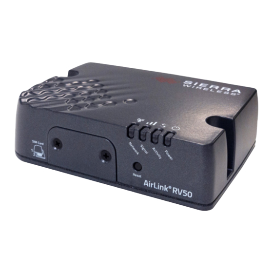
• Sierra Wireless
®
AirLink
®
RV50-X-LTE (032-1057 or 032-1052
*
Includes Safe Fleet data plan
Includes mounting screws, 10 ft./3 m power harness (4-wire)
• Cellular/LTE MIMO and GNSS window-mount antenna, 10 ft./3 m leads
(085-1129)
• Installation package (020-1070)
• 1A & 5A fuses, 2 fuse holders, and 2 butt-splice connectors
• GPS adapter (060-1101) and extension cable, 5 ft./1.5m length
(060-0122)
• Ethernet (CAT5e) patch cable - 5 ft./1.5 m length (085-0065)
Step 1: Install the Router
(continued)
Step 1d: Connect the power harness
Tip: Power-off timing
The router is configured with an internal timer for power management. It does not require a separate control signal from the recorder.
1. Connect the red wire (pin 1) from the power
harness to the 5A fuse holder.
a. Insert the fuse, and connect the fuse holder to
battery positive.
2. Connect the white wire (pin 3) to the 1A fuse
holder.
a. Insert the fuse, and connect the fuse holder to
vehicle ignition.
3. Connect the black wire (pin 2) to battery negative.
4. Connect the power harness to the router's DC
Power port.
Step
1:
Install the Router
Step
1a:
Mount the chassis
1. Select a secure, dry location that is not subject to constant vibration, with
enough clearance for easy access to cable connections.
Note: 5 ft./1.5 m cables run between the router and the recorder
Contact Technical Support if you require cable extensions.
2. The router has 2 mounting holes, as shown in the diagram below. Use the
holes on each side of the device enclosure to mark drilling positions, and
drill the 2 screw holes.
Chassis (underside view)
4.17"
106 mm
*
)
2.16"
55.06 mm
Mounting Holes (0.22"/5.5 mm diameter)
3. Fasten the Smart-Reach Cellular to the mounting surface with the 2
provided screws.
© Safe Fleet | 2022 | All rights reserved | Part #: 700-1206 R4
Step
1:
Install the Router
Step
1b:
Mount the Antenna
1. Choose a mounting location on the inside of the
windshield or a side window.
(10 ft./3 m) can reach the router.
Note: GPS signal quality
For optimal GPS and cellular signal quality,
DO NOT attach the antenna to the dashboard or
near metal.
1.1"
28.05 mm
2. Clean the mounting area with alcohol, and allow to dry.
3. Peel the backing from the adhesive, and attach the
antenna.
Step 2: Configure the Recorder
3
Note: Recorder firmware
If the router will communicate with a legacy DVR (DX-HD or TL 4/2), confirm the DVR is running current firmware.
If required, contact Technical Support for a DVR Firmware Upgrade Kit.
1. In the recorder menu, select
ConfigurationNetworkAdvanced.
a. Set Integrated VML to ON.
b. Enter a value in the LAN Range:
• If Wi-Fi is not installed: enter 10 into the first octet.
• If Wi-Fi is installed: contact Technical Support.
c. Click Back to save settings.
*
2. Select User Levels
a. For the default Admin user: change the Password to the first 8
characters of the Fleet ID (for more information, see the Smart-
Reach Cellular online setup documentation on the Safe Fleet
Community). If you need details on setting passwords, please
refer to the recorder documentation.
b. Create a User named admin (lowercase) and set the same
password used in the previous step. For the Level, select
Administrator.
c. Create a User named super, and set the password to "super".
Leave the Level at Playback.
d. Click Back to save settings.
(continued)
Step 1c: Wire the system
1. Connect the three antenna leads to the router as shown in the diagram below.
2. Connect the supplied Ethernet patch cable (085-0065) from the router's Ethernet port to an
Ethernet port
on the recorder.
*
3. Wire GPS from the router to the recorder:
a. Plug the male DB9 connector end of the supplied GPS adaptor (060-1101) into the
router's RS-232 serial port.
b. Use the supplied GPS extension cable (060-0122) to connect the 2x2 Microfit on the GPS
adaptor to the GPS port on the recorder.
Ensure antenna leads
Rear panel connections
Red antenna lead to
Cellular connector
Blue antenna lead to
GPS connector
For a list of recorder types and their Ethernet port names, see
*
"Recorders - Rear Ethernet Ports" on page 7
2
*
Recorder Ethernet
port
Red antenna lead to
to Ethernet connector
Diversity connector
Power harness to DC
GPS adapter/extension
Power port (see Step 1d)
to RS-232 port
4
*
On some older recorders, the
User Levels tab exists under
NetworkAdvanced.
Advertisement

Summary of Contents for Safe Fleet Smart-Reach Cellular
- Page 1 3. Fasten the Smart-Reach Cellular to the mounting surface with the 2 provided screws. • Ethernet (CAT5e) patch cable - 5 ft./1.5 m length (085-0065) © Safe Fleet | 2022 | All rights reserved | Part #: 700-1206 R4 Step 1: Install the Router Step 2: Configure the Recorder...
- Page 2 Rear Ethernet Ports Symptom Possible Cause Potential Solution Installation is not complete until online setup and system verification steps have been performed with the Safe Fleet Cloud software. NH16, NH16K, TH8 or TH6 MODEM The front panel The router is Wait 5-10 minutes.
Need help?
Do you have a question about the Smart-Reach Cellular and is the answer not in the manual?
Questions and answers