Table of Contents
Advertisement
Quick Links
Advertisement
Table of Contents

Summary of Contents for ensto Arcteq AQ-S391
- Page 1 AQ-S391 Bay control device Instruction manual...
-
Page 2: Table Of Contents
A A Q Q -S391 -S391 Instruction manual Version: 2.00 Table of contents 1 Document inf 1 Document informa ormation tion ..............................................3 3 2 Saf 2 Safe e t t y inf y informa ormation tion ................................................5 5 3 Abbr bbre e via viations... - Page 3 A A Q Q -S391 -S391 Instruction manual Version: 2.00 Disclaimer Please read these instructions carefully before using the equipment or taking any other actions with respect to the equipment. Only trained and qualified persons are allowed to perform installation, operation, service or maintenance of the equipment.
-
Page 4: Document Inf
A A Q Q -S391 -S391 1 Document information Instruction manual Version: 2.00 1 Document information Table. 1 - 1. History of Revision 1. R R e e vision vision 1.00 1.00 Date August 2011 Changes • The first revision of the manual. R R e e vision vision 1.01... - Page 5 A A Q Q -S391 -S391 1 Document information Instruction manual Version: 2.00 Table. 1 - 2. History of Revision 2. R R e e vision vision 2.00 2.00 Date February 2023 • Updated the Arcteq logo on the cover. •...
-
Page 6: Saf Y Informa Ormation Tion
A A Q Q -S391 -S391 2 Safety information Instruction manual Version: 2.00 2 Safety information This document contains important instructions that should be saved for future use. Read the document carefully before installing, operating, servicing, or maintaining this equipment. Please read and follow all the instructions carefully to prevent accidents, injury and damage to property. -
Page 7: Abbr Bbre E Via Viations Tions
A A Q Q -S391 -S391 3 Abbreviations Instruction manual Version: 2.00 3 Abbreviations A A C C alternating current A A VR automatic voltage regulator circuit breaker CBFP CBFP circuit breaker failure protection CPU U central processing unit C C T T current transformer C C T T S S current transformer supervision... - Page 8 A A Q Q -S391 -S391 3 Abbreviations Instruction manual Version: 2.00 intelligent electronic device IO IO inputs and outputs L L CD liquid-crystal display light-emitting diode normally closed normally open Network Time Protocol radio frequency R R CA relay characteristic angle root mean square SCAD SCADA A...
-
Page 9: General
A A Q Q -S391 -S391 4 General Instruction manual Version: 2.00 4 General The AQ S391 bay control IED is a member of the AQ-300 product line. The AQ-300 protection product line in respect of hardware and software is a modular device. The hardware modules are assembled and configured according to the application IO requirements and the software determines the available functions. -
Page 10: Ied User Interface Erface
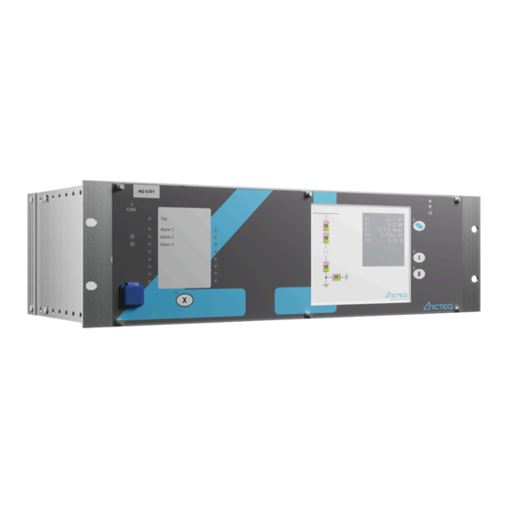
A A Q Q -S391 -S391 5 IED user interface Instruction manual 5.1 Front panel Version: 2.00 5 IED user interface 5.1 Front panel The figure below presents the front panel structure for AQ-300 series units, while the table below the image describes the functions of the front panel's various elements. -
Page 11: Led Assignment
5 IED user interface A A Q Q -S391 -S391 5.2 LED assignment Instruction manual Version: 2.00 Function Description The device has four (4) capacitive operational buttons: • "X" (below the LED label) latches and resets the LEDs. Operation • The button with a blue icon (top right) changes the touch screen menus. buttons •... - Page 12 A A Q Q -S391 -S391 5 IED user interface Instruction manual 5.3 Touch screen Version: 2.00 Main menu The main menu is the first one shown when the device is turned on. It displays general information such as the device and station names, the current time, and language options (when available). Figure.
- Page 13 5 IED user interface A A Q Q -S391 -S391 5.3 Touch screen Instruction manual Version: 2.00 Figure. 5.3 - 4. The password input screen. NOTICE! TICE! The lock icon is displayed even when the device has no password! Parameter menu In the parameters menu (below) you can view, set and edit certain parameters within the device.
- Page 14 A A Q Q -S391 -S391 5 IED user interface Instruction manual 5.3 Touch screen Version: 2.00 Figure. 5.3 - 5. The parameter set menu. The A A ctiv ctiva a t t e but e butt t on on activated the selected parameter set, which the device will now use. Depending on the device's configuration, the "Activate"...
- Page 15 5 IED user interface A A Q Q -S391 -S391 5.3 Touch screen Instruction manual Version: 2.00 • Floating-point number A number with a decimal point, entered with the number pad. Please note that the pad has the decimal point available only when the value can be entered as a floating-point number! •...
- Page 16 A A Q Q -S391 -S391 5 IED user interface Instruction manual 5.3 Touch screen Version: 2.00 Online measurement menu The online measurement menu displays real-time data depending on what is connected to the device. When you have selected a specific function block from the online functions list, clicking the V V ie iew w but butt t on takes you to a new window that displays the parameters and their current values.
- Page 17 5 IED user interface A A Q Q -S391 -S391 5.3 Touch screen Instruction manual Version: 2.00 Figure. 5.3 - 9. Event structure. NOTICE! TICE! The events menu does no not t display the whole event log, only the first few hundred items in the log! System settings menu Figure.
- Page 18 A A Q Q -S391 -S391 5 IED user interface Instruction manual 5.3 Touch screen Version: 2.00 Table. 5.3 - 4. The system settings. Setting Description System parameters and station bus settings Please contact your local network administrator for further information about these (IP address, settings.
-
Page 19: The Embedded Web Server
5 IED user interface A A Q Q -S391 -S391 5.4 The embedded web server Instruction manual Version: 2.00 Figure. 5.3 - 11. Turning on Q2. (1) First, we press Q2 on the touch screen to highlight the object. This causes Q2 to start blinking for a short while;... -
Page 20: Ethernet Connections
A A Q Q -S391 -S391 5 IED user interface Instruction manual 5.4 The embedded web server Version: 2.00 • provide remote or local firmware updgrades • perform administrative tasks. System requirements In order to access the device interface you need a compatible web browser as well as an Ethernet connection. - Page 21 5 IED user interface A A Q Q -S391 -S391 5.4 The embedded web server Instruction manual Version: 2.00 The diagram below depicts the three (3) different CPU versions and their structures: Figure. 5.4.1 - 12. The three CPU versions. Settings needed for Ethernet connection The AQ-300 devices can only be accessed over Ethernet-based communication protocols.
- Page 22 A A Q Q -S391 -S391 5 IED user interface Instruction manual 5.4 The embedded web server Version: 2.00 Make sure that your browser does NO NOT T use a proxy server while accessing an AQ-300 device. However, if there is a proxy server in your network, contact the system administrator and have them add an exception.
- Page 23 5 IED user interface A A Q Q -S391 -S391 5.4 The embedded web server Instruction manual Version: 2.00 Figure. 5.4.1 - 14. Using the RJ45 connection. The crossover cable's pinout has been depicted in the diagram below: Figure. 5.4.1 - 15. The pinout of the crossover cable. Please note that the cable's RJ45 connector can also be connected to an Ethernet switch.
-
Page 24: Getting Started
A A Q Q -S391 -S391 5 IED user interface Instruction manual 5.4 The embedded web server Version: 2.00 ST-type fiber optic connection The ST-type fiber optic connector of the 100Base-FX Ethernet provides a connection to an Ethernet switch with an identical fiber optic input. When using this connection, all the network's IEDs with client functionalities (e.g. - Page 25 5 IED user interface A A Q Q -S391 -S391 5.4 The embedded web server Instruction manual Version: 2.00 Figure. 5.4.2 - 17. Web server elements. The menu that is currently selected is highlighted in black (in the image above, the main menu is selected).
-
Page 26: Menu Items
A A Q Q -S391 -S391 5 IED user interface Instruction manual 5.4 The embedded web server Version: 2.00 5.4.3 Menu items Main menu Figure. 5.4.3 - 18. The main menu and its elements. In the main menu you can control the device's front panel. The image of a touch screen (located on the right) behaves the same way as the actual touch screen. - Page 27 5 IED user interface A A Q Q -S391 -S391 5.4 The embedded web server Instruction manual Version: 2.00 Parameters menu Figure. 5.4.3 - 19. The parameters menu and its elements. You can view and change various parameters and variables in this menu. You can manage the different parameter sets by resetting, renaming, exporting and importing them.
- Page 28 A A Q Q -S391 -S391 5 IED user interface Instruction manual 5.4 The embedded web server Version: 2.00 In the "Parameter set" section of the page there are options for managing the parameter sets. The section lists all the available parameter sets, and each can be manipulated with the buttons located on the right of the line.
- Page 29 5 IED user interface A A Q Q -S391 -S391 5.4 The embedded web server Instruction manual Version: 2.00 Figure. 5.4.3 - 21. The system settings menu. Table. 5.4.3 - 6. The system setting sections and their content. Section name Description If enabled, the device asks you to confirm the saving of new settings by pressing the "I"...
- Page 30 A A Q Q -S391 -S391 5 IED user interface Instruction manual 5.4 The embedded web server Version: 2.00 Section name Description Contain the parameters to control the LCD panel's behaviour. The light switches off after its set timeout. LCD backlight The "Backlight group"...
- Page 31 5 IED user interface A A Q Q -S391 -S391 5.4 The embedded web server Instruction manual Version: 2.00 Figure. 5.4.3 - 23. Elements of the events menu. With the R R e e fr fresh esh button you can refresh the list displaying the events, the E E ra rase all e se all ev v ents ents button clears the list on the screen, and the Expor...
- Page 32 A A Q Q -S391 -S391 5 IED user interface Instruction manual 5.4 The embedded web server Version: 2.00 Figure. 5.4.3 - 25. Disturbance recorder. The "Recorded disturbances" section lists all disturbance records. You can refresh the list with the R R e e fr fresh esh button to display any new disturbance records that have occurred after the page was opened or refreshed last.
- Page 33 5 IED user interface A A Q Q -S391 -S391 5.4 The embedded web server Instruction manual Version: 2.00 You can set a setpoint by clicking anywhere on the graph, and the positioning the cursor to a desired second point. The preview then displays the timestamp of the first setpoint, and the time difference between the two setpoints.
- Page 34 A A Q Q -S391 -S391 5 IED user interface Instruction manual 5.4 The embedded web server Version: 2.00 Advanced Figure. 5.4.3 - 29. The Advanced menu. This menu displays the additional, more advanced options. You can set a password request before a user is allowed access to these options.
- Page 35 5 IED user interface A A Q Q -S391 -S391 5.4 The embedded web server Instruction manual Version: 2.00 The Ge Get r t repor eport t button generates a .zip file that has all of the log files archived together. The files have valuable information and they can help in analyzing errors and malfunctions;...
-
Page 36: Troubleshooting
A A Q Q -S391 -S391 5 IED user interface Instruction manual 5.4 The embedded web server Version: 2.00 Figure. 5.4.3 - 32. Update manager. 5.4.4 Troubleshooting Some browsers have a tendency to handle and cache various JavaScript function improperly, and this may cause anomalies and errors in the interface. -
Page 37: Applica A Tion
6 Application A A Q Q -S391 -S391 5.4 The embedded web server Instruction manual Version: 2.00 6 Application The AQ S391 bay control IED is suitable to various types of control and monitoring applications in extra-high voltage, high voltage and medium voltage applications. The modular hardware construction offers required options for different kind of bay configurations in terms of type and quantity of analogue and digital signals. -
Page 38: Main Characteristics Of The A
A A Q Q -S391 -S391 7 Main characteristics of the AQ-S391 bay control system Instruction manual 5.4 The embedded web server Version: 2.00 7 Main characteristics of the AQ-S391 bay control system List of the main characteristics • Flexible and modular hardware construction allowing for multiple sets of current and voltage measurement modules, digital input and output modules and mA input modules •... -
Page 39: Soft E Set T Up Up
8 Software setup A A Q Q -S391 -S391 8.1 Functions included in AQ-S391 Instruction manual Version: 2.00 8 Software setup 8.1 Functions included in AQ-S391 In this chapter are presented the control and monitoring functions, listed in the table below. The function blocks are described in detail in following chapters. - Page 40 A A Q Q -S391 -S391 8 Software setup Instruction manual 8.2 Control, monitoring and measurements Version: 2.00 • All necessary timing tasks are performed within the function block: ◦ Time limitation to execute a command ◦ Command pulse duration ◦...
- Page 41 8 Software setup A A Q Q -S391 -S391 8.2 Control, monitoring and measurements Instruction manual Version: 2.00 The symbol of the function block in the AQtivate 300 software Figure. 8.2.1 - 34. Function block symbol of circuit breaker control. The binary input and output status signals of the circuit breaker control are listed in tables below.
- Page 42 A A Q Q -S391 -S391 8 Software setup Instruction manual 8.2 Control, monitoring and measurements Version: 2.00 Table. 8.2.1 - 12. The binary output status signals of the circuit breaker control. Binary status signal Title Explanation Off command impulse, the duration of which is CB1Pol_CmdOff_GrI_ Off Command defined by the parameter "Pulse length".
- Page 43 8 Software setup A A Q Q -S391 -S391 8.2 Control, monitoring and measurements Instruction manual Version: 2.00 In the Figure above the local/remote selection is made by another function block (Common). In VB1Pol, synchro check is not applied, the input “SynOK” is programmed for constant “True”. The circuit breaker can be switched any time, no interlocking is needed, the “EnaOff”...
-
Page 44: Disconnector Control Function
A A Q Q -S391 -S391 8 Software setup Instruction manual 8.2 Control, monitoring and measurements Version: 2.00 Setting value, Parameter range, and Description step Length of the time period to wait for the synchroswitch pulse (see synchrocheck/synchroswitch function description). After this time the Max.SynSW time 0...60,000 ms function resets and no switching is performed. - Page 45 8 Software setup A A Q Q -S391 -S391 8.2 Control, monitoring and measurements Instruction manual Version: 2.00 Table. 8.2.2 - 14. Status variable of the circuit breaker control. Status variable Title Explanation 0: Intermediate 1: Off DisConn I_stVal_Ist_ Status 2: On 3: Bad The available control channel to be selected is:...
- Page 46 A A Q Q -S391 -S391 8 Software setup Instruction manual 8.2 Control, monitoring and measurements Version: 2.00 Binary status signal Title Explanation The active state of this input enables the opening of the disconnector. The state is usually DisConn_EnaOff_GrO_ EnaOff generated by the interlocking conditions defined by the user.
- Page 47 8 Software setup A A Q Q -S391 -S391 8.2 Control, monitoring and measurements Instruction manual Version: 2.00 Configuration example Figure. 8.2.2 - 38. Simulation of the disconnector (and circuit breaker; detail). In the Figure above the local/remote selection is made by another function block (Common). The disconnector cannot be switched any time: interlocking is needed;...
-
Page 48: Dead Line Detection (Dld)
A A Q Q -S391 -S391 8 Software setup Instruction manual 8.2 Control, monitoring and measurements Version: 2.00 Setting value, Parameter range, and Description step Length of the time period to wait for the conditions of the synchronous Max.SynChk state. After expiry of this time, the synchroswitch procedure is initiated (see 10...5,000 ms time synchrocheck/synchroswitch function description). - Page 49 8 Software setup A A Q Q -S391 -S391 8.2 Control, monitoring and measurements Instruction manual Version: 2.00 Figure. 8.2.3 - 40. The function block of the dead line detection function. The binary input and output status signals of the dead line detection function are listed in tables below. Table.
-
Page 50: Voltage Transformer Supervision (Vts)
A A Q Q -S391 -S391 8 Software setup Instruction manual 8.2 Control, monitoring and measurements Version: 2.00 Setting Parameter value/ Step Default Description range Minimum current threshold for detecting the dead line status. If all the Min. 8…100 phase to ground voltages are under the setting "Min. operate voltage" operate 10 % and also all the phase currents are under the "Min. - Page 51 8 Software setup A A Q Q -S391 -S391 8.2 Control, monitoring and measurements Instruction manual Version: 2.00 Figure. 8.2.4 - 41. Operation logic of the voltage transformer supervision and dead line detection. The voltage transformer supervision logic operates through decision logic presented in the following figure.
-
Page 52: Synchrocheck (Dv/Da/Df; 25)
A A Q Q -S391 -S391 8 Software setup Instruction manual 8.2 Control, monitoring and measurements Version: 2.00 Figure. 8.2.4 - 43. The function block of the voltage transformer supervision function. The binary input and output status signals of voltage transformer supervision function are listed in tables below. - Page 53 8 Software setup A A Q Q -S391 -S391 8.2 Control, monitoring and measurements Instruction manual Version: 2.00 To prevent such problems, this function checks if the systems to be interconnected are operating synchronously. If yes, then the close command is transmitted to the circuit breaker. In case of asynchronous operation, the close command is delayed to wait for the appropriate vector position of the voltage vectors on both sides of the circuit breaker.
- Page 54 A A Q Q -S391 -S391 8 Software setup Instruction manual 8.2 Control, monitoring and measurements Version: 2.00 Figure. 8.2.5 - 44. Operation logic of the synchrocheck function. The synchro check/synchro switch function contains two kinds of software blocks: • SYN25_Com = a common block for manual switching and automatic switching. •...
- Page 55 8 Software setup A A Q Q -S391 -S391 8.2 Control, monitoring and measurements Instruction manual Version: 2.00 If the active bus section changes the function is dynamically blocked for 1000ms and no release signal or switching command is generated. The processed line voltage is selected based on the preset parameter (Voltage select).
- Page 56 A A Q Q -S391 -S391 8 Software setup Instruction manual 8.2 Control, monitoring and measurements Version: 2.00 If the conditions are fulfilled for at least 45 ms, then the function generates a release output signal (Release Auto/Manual).If the conditions for synchro check operation are not fulfilled and a close request is received as the input signal (SySwitch Auto/Manual), then synchro switching is attempted.
- Page 57 8 Software setup A A Q Q -S391 -S391 8.2 Control, monitoring and measurements Instruction manual Version: 2.00 Binary status signal Title Explanation Cancel SYN25_CancelM_GrO_ Signal to interrupt (cancel) the manual switching procedure. Manual Table. 8.2.5 - 25. The binary output signals. Binary status signal Title Explanation...
- Page 58 A A Q Q -S391 -S391 8 Software setup Instruction manual 8.2 Control, monitoring and measurements Version: 2.00 Setting Parameter value/ Step Default Description range Breaker operating time at closing. This parameter is used for the synchroswitch closing command compensation and it Breaker Time 0…500 ms 80 ms...
- Page 59 8 Software setup A A Q Q -S391 -S391 8.2 Control, monitoring and measurements Instruction manual Version: 2.00 Setting Parameter value/ Step Default Description range Manual synchroswitching selection. Selection may be enabled SynSW Man "On" or disabled "Off". Deadbus Energizing mode of manual synchroswitching. Selections LiveLine Energizing DeadBus...
- Page 60 A A Q Q -S391 -S391 9 Application examples Instruction manual 8.2 Control, monitoring and measurements Version: 2.00 9 Application examples One and a half circuit breaker configuration Figure. 9 - 48. Application example of a one-and-a-half circuit breaker configuration. DC 1 POSITION IND DC 1 CONTROL +110 VDC...
- Page 61 9 Application examples A A Q Q -S391 -S391 8.2 Control, monitoring and measurements Instruction manual Version: 2.00 IED IO positions in one and a half circuit breaker configuration Figure. 9 - 49. Application example of the IO positions in a one-and-a-half circuit breaker configuration. O12+ 1101 PS+ 1030 DI 1...
-
Page 62: Construction And Installation Tion
A A Q Q -S391 -S391 10 Construction and installation Instruction manual 10.1 Construction Version: 2.00 10 Construction and installation 10.1 Construction The AQ-S391 bay control IED consists of hardware modules. Due to modular structure optional positions for the slots can be user defined in the ordering of the IED to include I/O modules and other types of additional modules. -
Page 63: Cpu Module
10 Construction and installation A A Q Q -S391 -S391 10.2 CPU module Instruction manual Version: 2.00 10.2 CPU module Figure. 10.2 - 52. Communication card with 100Base-FX Ethernet MM/LC 1300 nm, 50/62.5/125 μm connector, (up to 2 km) fiber. The CPU module contains all the protection, control and communication functions of the AQ-300 device. -
Page 64: Power Supply Module
A A Q Q -S391 -S391 10 Construction and installation Instruction manual 10.3 Power supply module Version: 2.00 • Embedded WEB-server: ◦ Firmware upgrade possibility ◦ Modification of user parameters ◦ Events list and disturbance records ◦ Password management ◦ Online data measurement ◦... - Page 65 10 Construction and installation A A Q Q -S391 -S391 10.3 Power supply module Instruction manual Version: 2.00 The power supply module converts primary AC and/or DC voltage to required system voltages. In most applications, one power supply module is sufficient to provide the required power to the system. Redundant power supply modules extend system availability in case of the outage of any power source.
-
Page 66: Binary Input Module(S)
A A Q Q -S391 -S391 10 Construction and installation Instruction manual 10.4 Binary input module(s) Version: 2.00 10.4 Binary input module(s) The inputs are galvanic isolated and the module converts high-voltage signals to the voltage level and format of the internal circuits. Table. - Page 67 10 Construction and installation A A Q Q -S391 -S391 10.4 Binary input module(s) Instruction manual Version: 2.00 Module type O16+2401 O16+4801 O16+1101 O16+2201 Time Configured via Configured via Configured via Configured via synchronization AQtivate 300 AQtivate 300 AQtivate 300 AQtivate 300 Rated voltage 24 V...
-
Page 68: Binary Output Module(S)
A A Q Q -S391 -S391 10 Construction and installation Instruction manual 10.5 Binary output module(s) Version: 2.00 Figure. 10.4 - 54. Binary input modules. 10.5 Binary output module(s) The signaling module has 4, 8, 12 or 16 relay outputs with dry contacts. Table. - Page 69 10 Construction and installation A A Q Q -S391 -S391 10.5 Binary output module(s) Instruction manual Version: 2.00 Table. 10.5 - 32. Hardware data for the different R8 module types. Module type R8+00 R8+80 R8+C0 Rated voltage 250 V AC/DC 250 V AC/DC 250 V AC/DC Continuous carry...
- Page 70 A A Q Q -S391 -S391 10 Construction and installation Instruction manual 10.5 Binary output module(s) Version: 2.00 • Breaking capacity max.: 2000 VA • Short time carrying capacity: 1 s, 35 A • Limiting making current, max. 4 s: 15 A (df = 10 %) •...
-
Page 71: 9Di + Bnc Irig-B
10 Construction and installation A A Q Q -S391 -S391 10.6 9DI + BNC IRIG-B Instruction manual Version: 2.00 10.6 9DI + BNC IRIG-B Figure. 10.6 - 56. The O9S+2121 module. The inputs are galvanic isolated and the module converts high-voltage signals to the voltage level and format of the internal circuits. -
Page 72: Milliampere Module
A A Q Q -S391 -S391 10 Construction and installation Instruction manual 10.7 Milliampere module Version: 2.00 10.7 Milliampere module Figure. 10.7 - 57. The milliampere (mA) input module AIC +0200. The analog input module accepts transducers current outputs. The AIC module can measure unipolar and bipolar current values in wide ranges. -
Page 73: Tripping Module
10 Construction and installation A A Q Q -S391 -S391 10.8 Tripping module Instruction manual Version: 2.00 10.8 Tripping module Figure. 10.8 - 58. The tripping module TRIP+ 2101. The tripping module applies direct control of a circuit breaker. The module provides fast operation and is rated for heavy duty controlling. -
Page 74: Rtd Module
A A Q Q -S391 -S391 10 Construction and installation Instruction manual 10.9 RTD module Version: 2.00 10.9 RTD module Figure. 10.9 - 59. The RTD +1100 module. The RTD+1100 module is used to measure the temperature through the variation of resistance of temperature detectors. - Page 75 10 Construction and installation A A Q Q -S391 -S391 10.9 RTD module Instruction manual Version: 2.00 Figure. 10.9 - 61. 3-wire RTD wiring. Figure. 10.9 - 62. 4-wire RTD wiring. Figure. 10.9 - 63. 4-wire RTD wiring. of potentiometer. ©...
-
Page 76: Voltage Measurement Module
A A Q Q -S391 -S391 10 Construction and installation Instruction manual 10.10 Voltage measurement module Version: 2.00 10.10 Voltage measurement module Figure. 10.10 - 64. The voltage measurement module VT+ 2211. For voltage related functions (over- /under -voltage, directional functions, distance function,power functions) or disturbance recorder functionality this module is needed. -
Page 77: Current Measurement Module
10 Construction and installation A A Q Q -S391 -S391 10.11 Current measurement module Instruction manual Version: 2.00 10.11 Current measurement module Figure. 10.11 - 65. Connector allocation of the current measurement module. Current measurement module is used for measuring current transformer output current. Module includes three phase current inputs and one zero sequence current input. -
Page 78: Installation And Dimensions
A A Q Q -S391 -S391 10 Construction and installation Instruction manual 10.12 Installation and dimensions Version: 2.00 10.12 Installation and dimensions Figure. 10.12 - 66. Dimensions of AQ-x39x IED. Figure. 10.12 - 67. Panel cut-out and spacing of AQ-x39x IED. ©... -
Page 79: Technic Echnical Da Al Data Ta
11 Technical data A A Q Q -S391 -S391 11.1 Control functions Instruction manual Version: 2.00 11 Technical data 11.1 Control functions Circuit breaker control function Operation time inaccuracy ±5 % or ±15 ms, whichever is greater Disconnector control function Operation time inaccuracy ±5 % or ±15 ms, whichever is greater Synchroncheck function du/df (25) -
Page 80: Hardware
A A Q Q -S391 -S391 11 Technical data Instruction manual 11.3 Hardware Version: 2.00 Dead line detectioin (DLD) Pick-up voltage inaccuracy Operation time inaccuracy <20ms Reset ratio 0.95 11.3 Hardware Power supply module 80-255VAC Input voltage 90-300VDC Nominal voltage 110VDC/220VDC Maximum interruption 100ms... - Page 81 11 Technical data A A Q Q -S391 -S391 11.3 Hardware Instruction manual Version: 2.00 250V (continuous) Voltage withstand 275VAC/350VDC (1s) Voltage measurement range 0.05-1.2xUn 0.61VA at 200V Power consumption 0.2 VA at 100V Relative accuracy ±0.5 % (>0.6Un) Frequency measurement range ±0.01 % at Ux ≥...
-
Page 82: Tests And Environmental Conditions
A A Q Q -S391 -S391 11 Technical data Instruction manual 11.4 Tests and environmental conditions Version: 2.00 ± 20 mA (typical 0-20, 4-20 mA) Measurement ranges Rload = 56 Ω 11.4 Tests and environmental conditions Disturbance tests CE approved and tested according to EN EMC test 50081-2, EN 50082-2 Emission... - Page 83 11 Technical data A A Q Q -S391 -S391 11.4 Tests and environmental conditions Instruction manual Version: 2.00 Environmental conditions Specified ambient service temp. range -10…+55°C Transport and storage temp. range -40…+70°C IED lifetime > 20 years © Arcteq Relays Ltd IM00076...
-
Page 84: Ordering Inf Dering Informa Ormation Tion
A A Q Q -S391 -S391 12 Ordering information Instruction manual 11.4 Tests and environmental conditions Version: 2.00 12 Ordering information Visit https://configurator.arcteq.fi/ to build a hardware configuration, define an ordering code and get a module layout image. © Arcteq Relays Ltd IM00076... -
Page 85: Contact And R Ence Informa Ormation Tion
13 Contact and reference information A A Q Q -S391 -S391 11.4 Tests and environmental conditions Instruction manual Version: 2.00 13 Contact and reference information Manufacturer Arcteq Relays Ltd. Visiting and postal address Kvartsikatu 2 A 1 65300 Vaasa, Finland Contacts Phone: +358 10 3221 370...