Table of Contents
Advertisement
Quick Links
Advertisement
Table of Contents

Summary of Contents for 6TL YAV90132
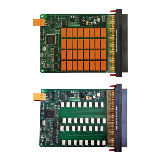
- Page 1 TECHNICAL DESCRIPTION YAV90132 / YAV90133 32 channel, 2A SPDT Relays...
-
Page 2: Table Of Contents
SWITCH CONFIGURATION................... 8 HARDWARE SPECIFICATIONS ..................9 OPERATION ........................ 10 11.1 PHI6 EXPLORER soft interface ................ 10 LOW LEVEL CAN COMMANDS ................... 11 ACCESSORIES ......................12 UNPACKAGING AND INSTALLING ................12 Pag 2 | 13 www.6tlengineering.com 18/06/2022 YAV90132 / YAV90133... -
Page 3: Safety Guidelines
ELECTROMAGNETIC COMPATIBILITY GUIDELINES The product YAV90132 / YAV90133 to which this manual relates meet the provisions of the EU Directives 2014/30/CE which declares the compliance of electromagnetic compatibility (EMC) and directive 2014/35/CE of low voltages electronic devices. -
Page 4: Description
• 1x 4 relays NO sharing the common pin. P/N YAV90132 contacts are for general purpose applications and up to 2A continuous current, being . P/N YAV90133, with the same functionality and electrically compatible, has contacts designed to carry a maximum of 2A, but with better behaviour for low voltage signals. -
Page 5: Relay Distribution
RELAY DISTRIBUTION Pag 5 | 13 www.6tlengineering.com 18/06/2022 YAV90132 / YAV90133... -
Page 6: Pinout (Front)
PINOUT (FRONT) Module function Receiver Pos. # I.T.A. Module P/N 510 108 126 I.T.A. contact P/N 610 110 108 YAV90132: 32 SPDT relays Description Description Description CAN L +24V CAN H NC relay K1 NO relay K1 NC relay K2... -
Page 7: Connector Pinout (Rear)
Pin Number Signal Description Ground connection +24V Board power supply CAN L CAN-Bus Low signal CAN H CAN-Bus High signal X1 pinout description Plug type: • Manufacturer: Weidmuller • Model: BLZF 3.50/04/180 Pag 7 | 13 www.6tlengineering.com 18/06/2022 YAV90132 / YAV90133... -
Page 8: Led Behaviour
Must be OPEN on operation. A temporary bridge causes a reset of the board. CAN-END Placing jumper adds a 120 Ohm resistor between the CAN-High and CAN-Low signals of CAN-Bus. Switches description Pag 8 | 13 www.6tlengineering.com 18/06/2022 YAV90132 / YAV90133... -
Page 9: Hardware Specifications
Power Dissipation (TA = 25 ºC) Operation specifications Switching specifications Property Min. Typ. Max. Units • Rated current • Maximum switching voltage AC Switching specifications YAV90132 Relays contact specifications Property Min. Typ. Max. Units • 1250 Maximum switching power AC • 15x10^6 Cycles Mechanical endurance •... -
Page 10: Operation
11. OPERATION Through the PHI6 Explorer soft panel the user can interface with the YAV90132 board manually. This tool is a very useful for table-top debugging of test-systems or system maintenance on-site. Activate relays By clicking a relay in the panel, the relay closes and its status in the panel is updated. -
Page 11: Low Level Can Commands
Relays 0 Relays 1 Relays 2 Relays 3 0x06 ASK ALL Relays 0x155103xx 0x03 0x04 Autosend All Relays Status Tx 0x155203xx 0x03 0x04 Relays 0 Relays 1 Relays 2 Relays 3 Pag 11 | 13 www.6tlengineering.com 18/06/2022 YAV90132 / YAV90133... -
Page 12: Accessories
To start using the product just remove vacuum bag carefully to avoid damage. To install the YAV90132 / YAV90133 simply insert the module on a VPC receiver, vertical or horizontally, according to the Receiver arrangement. Once it is completely inserted, fix YAV module with two 4-40 UNC screws on each side of connector. - Page 13 Finally, connect the X1 rear plug of CAN bus and power supply (24VDC) to start using the module. Pag 13 | 13 www.6tlengineering.com 18/06/2022 YAV90132 / YAV90133...
Need help?
Do you have a question about the YAV90132 and is the answer not in the manual?
Questions and answers