Table of Contents
Advertisement
Advertisement
Table of Contents

Summary of Contents for ANDELI TIG-250PL ACDC
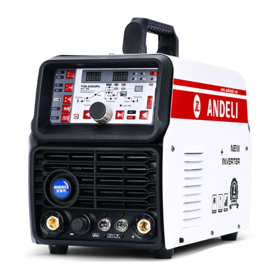
- Page 1 OPERATOR’S MANUAL INVERTER AC/DC PULSED TIG WELDER TIG-250PL ACDC...
-
Page 2: Table Of Contents
CONTENT 1 SAFETY..............................1 ..........................1 1.1 S IGNAL XPLANATION 1.2 A ........................1 ELDING AMAGE ................5 1.3 T HE KNOWLEDGE OF LECTRIC AND AGNETIC IELDS 2 SUMMARY...............................6 2.1 B ..........................6 RIEF NTRODUCTION 2.2 M ..........................7 ODULE XPLANATION 2.3 W .......................... -
Page 3: Safety
SAFETY 1 SAFETY 1.1 Signal Explanation The above signals mean warning! Notice! Running parts and getting an electric shock or thermal parts will take damage for your body or others. The corresponding notices are as follows. It is quite a safe operation after taking several necessary protection measures. - Page 4 SAFETY semiautomatic welding gun are also electrically “hot”. Always be sure the work cable makes a good electrical connection with the metal being welded. The connection should be as close as possible to the area being welded. Maintain the electrode holder, work clamp, welding cable and welding machine in good, safe operating condition.
- Page 5 SAFETY the arc when welding or observing open arc welding. Use suitable clothing made from durable flame-resistant material to protect your skin and that of your helpers from the arc rays. Protect other nearby personnel with suitable, non-flammable screening and /or warn them not to watch the arc nor expose themselves to the arc rays or to hot spatter or metal.
- Page 6 SAFETY an explosion even though they have been “cleaned”. Vent hollow castings or containers before heating, cutting or welding. They may explode. Sparks and spatter are thrown from the welding arc. Wear oil free protective garments such as leather gloves, heavy shirt, cuff less trousers, high shoes and a cap over your hair.
-
Page 7: The Knowledge Of Electric And Magnetic Fields
SAFETY 1.3 The knowledge of Electric and Magnetic Fields Electric current flowing through any conductor causes localized Electric and Magnetic Fields (EMF). The discuss on the effect of EMF is ongoing all the world. Up to now, no material evidences show that EMF may have effects on health. -
Page 8: Summary
SUMMARY 2 SUMMARY 2.1 Brief Introduction TIG-250PL AC/DC welding machine adopts the latest pulse width modulation (PWM) technology and insulated gate bipolar transistor (IGBT) power module, which can change work frequency to medium frequency so as to replace the traditional hulking work frequency transformer with the cabinet medium frequency transformer. -
Page 9: Module Explanation
SUMMARY AC TIG AC Pulse TIG 1.For DC TIG, DCEP is used normally (workpiece connected to positive polarity, while torch connected to negative polarity). This connection has many characters, such as stable welding arc, low tungsten pole loss, more welding current, narrow and deep weld; 2.For AC TIG (rectangle wave), arc is more stable than Sine AC TIG. -
Page 10: Working Principle
SUMMARY 2.3 Working Principle The working principle of TIG-250PL welding machines is shown as the following figure. Single-phase 220V work frequency AC is rectified into DC (about 312V), then is converted to medium frequency AC (about 20KHz) by inverter device (IGBT module), after reducing voltage by medium transformer (the main transformer) and rectifying by medium frequency rectifier (fast recovery diodes), then is outputted DC or AC by selecting IGBT module. -
Page 11: Installation And Adjustment
INSTALLATION AND ADJUSTMENT (V) Volt-ampere characteristic The relation between the conventional loading Working voltage and welding current point (A) 3 Installation and Adjustment 3.1 Parameters Models TIG-250PL ACDC Parameters Input power 1~220±10%,50Hz Rated input current(A) 26(TIG) Rated input power ( KW) 5.7(TIG)... -
Page 12: Duty Cycle & Over Heat
INSTALLATION AND ADJUSTMENT Power factor 0.76 Max no-load voltage(V) Adjustment range LIFT start current(A) 10~welding current 30~welding 10~welding current current Adjustment range 10~200 30~200 10~200 welding current(A) Adjustment range 10~200 30~200 10~200 Crater arc current(A) Adjustment range 0~5 downslope time(S) Pre-gas time(S)... -
Page 13: Movement And Placement
INSTALLATION AND ADJUSTMENT shown as the right figure. If the welder is over-heat, the IGBT over-heat protection unit inside it will output an instruction to cut output welding current, and brighten the over-heat pilot lamp on the front panel. At this time, the machine should be relaxed for 15 minutes to cool the fan. When operating the machine again, the welding output current or the duty cycle should be reduced. -
Page 14: Assembling The Equipment (Tig)
INSTALLATION AND ADJUSTMENT Set the voltage stabilization device in the front of power cable input. 3.5 Assembling the equipment (TIG) Workpiece is connected to the positive electrode of welding machine, and welding torch is connected to the negative electrode, which is called DC POSITIVE CONNECTION; otherwise, that is called DC NEGATIVE CONNECTION. -
Page 15: Operation
MAINTENANCE AND TROUBLESHOOTING 4 Operation 4.1 Layout for the panel Positive output The welder’s positive polarity output. Aero socket Is connected to torch switch control wire. Negative output The welder’s negative polarity output. Shield gas connector Is connected to the gas input pipe of torch. Power source switch Switch to “ON”, the welder is turned on, while switch to “OFF”, the welder is turned off. -
Page 16: Control Panel
INSTALLATION AND ADJUSTMENT 4.2 Control panel (12) Welding current display (11) Welding voltage/other parameter display (1) AC/DC selecting key (2) Mode selecting key (3) Gas-test key (10) Cool HZ/Time (4) The program to save (9) Rod electrode welding key (5) Pulse key (7) Parameter selection key (6) Parameter selection key (8) Adjusting dial... -
Page 17: Parameters
INSTALLATION AND ADJUSTMENT Overview The key feature of the control panel is the logical way in which the controls are arranged. All the main parameters needed for day-to-day working can easily be -selected with the keys -altered with the adjusting dial -shown on the display during welding. - Page 18 MAINTENANCE AND TROUBLESHOOTING Available parameters where 2T mode have been selected: Pre-flow time Unit Setting range 0.1—1 Factory setting Start (No such function) Upslope time Unit Setting range 0—10 Factory setting TIG :Welding current Unit TIG-250 10—200 (TIG-DC);10—200 (TIG-AC-HF); 30—200 (TIG-AC-LIFT); Base :Base current Unit TIG-250PL...
- Page 19 MAINTENANCE AND TROUBLESHOOTING Factory setting Stop: Crater arc current (No such function) Post-flow Unit Setting range 0.1—10 Factory setting Hz: AC frequency (only with TIG-AC) Unit Setting range 50—250 (Iw<50A) 50—200 (50A≤Iw<100A) 50—150 (100A≤Iw<150A) 50—100 (150A≤Iw<200A) Balance (only with TIG-AC) Balance adjustment is mainly used to set the adjustment of eliminating metal-oxide (such as Aluminium, Magnesium and its alloy) while AC output.
- Page 20 MAINTENANCE AND TROUBLESHOOTING After the start of welding, the right-hand display shows the present actual value of the welding voltage. (10) Welding current display Display the pre-set or the actual welding current value. Before the start of welding, the left-hand display shows the pre-set current value of Is, Iw, Ib and After the start of welding, the left-hand display shows the present actual value of the welding current.
Need help?
Do you have a question about the TIG-250PL ACDC and is the answer not in the manual?
Questions and answers