Advertisement
Quick Links
Advertisement

Subscribe to Our Youtube Channel
Related Manuals for Medicatech MasterRad30

Summary of Contents for Medicatech MasterRad30
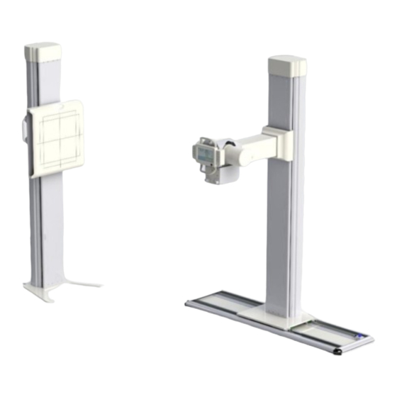
- Page 1 Installation Manual MasterRad30 Universal Radiographic System Page 1 of 15 Rev. 01...
- Page 2 Introduction: Important! .. X-ray Protection X-RAY EQUIPMENT IS DANGEROUS TO BOTH PATIENT AND OPERATOR UNLESS MEASURES OF PROTECTION ARE STRICTLY OBSERVED X-ray equipment if not properly used may cause injury. Accordingly, the instructions herein should be thorougly read and understood before attempting to place this equipment in operation.
-
Page 3: Pre-Installation Checks
SECTION 1: INSTALLATION 1.1 TOOLS The following hand tools are required for the installation: • Standard service engineers tool kit. • Electric drill motor and assorted bits. 1.2 Pre-installation checks Prior to beginning installation, it is recommended to inspect the sire and verify that the x-ray room complies with requirement such as: •... - Page 4 Page 4 of 15 Rev. 01...
-
Page 5: Hardware Installation
1. Hardware Installation: 1.1. Refer to the layout of the room 1.2. Locate and unscrew the 10 x allen flat head screws #10-32 screws 5x Allen flat head #10-32 screws Floor mount Brake strips cover 5x Allen flat head #10-32 screws Figure 1:take the bare strips and the floor mount cover 1.3. - Page 6 1.6. Using a 3/8” cement drill bit, Drill 7 mounting holes (refer to figure 2) Figure 2: floor mount mounting holes 1.7. Place the washer and the nut on the anchor, as it will be hard to place them after hammering the anchors in the floor.
- Page 7 Figure 3:place the tube stand on the floor mount. 1.11. Align the tube mount base with the 4 carts on the floor mount. 1.12. Use the 16 xM6 screws to connect the tube stand to the floor mount. (figure 4) Figure 4: 16x M6 screws Page 7 of 15 Rev.
- Page 8 1.13. Place the 4 side covers and the 4 corners simply by connecting them and place them around the floor mount (refer to figure 5) 1.14. Make sure that the side cover with the cable tray attached is at the back side. Side covers Corners Figure 5: showing the top cover, brake strips, side cover and corner.
- Page 9 Tube , collimator, and generator installation (all cables are going to the back of the tube stand and through the cable tray) 1.26. Place the tube on top of the arm. 1.27. Place the collimator ring at the bottom of the arm below the tube through the 1.28.
- Page 10 2.1.3. remove the collimator mounting plate 2.1.4. connect the collimator mounting plate to the tube using the screws previously used to align and keep tube in place 2.1.5. place collimator on to mounting plate and tighten all four screws in order to secure collimator on the tube arm 2.1.6.
- Page 11 Figure 9: internal wiring of the tube. 2.2.6. Screw the cap back on 2.2.7. Feed the loose end of the grey cable through the arm and through to the bottom access point 2.3. Generator connections: 2.3.1. Connect the high-tension cables to the tubes. 2.3.1.1.
- Page 12 2.3.3.2. Connect the positive end of the cable to the positive end inside the generator and so for the negative Figure 10: connecting the high tension cables to the generator 2.3.4. Close the generator cover 2.3.5. Organize the cables through the cable tray 2.3.6.
- Page 13 4. Electrical connections 4.1. Mount the relay box to the back of the tube stand 4.2. Connect the wires to the relay box as follow: 4.2.1. 1. Use the lemo connector (black wire with silver head) a. Connect the cable to the back of the control panel. b.
- Page 14 6. Connect the rotation brakes (wire from the arm) 7. Skip 8. Connect the floor mount brakes 9. Skip 10. Skip 11. Power cable 5. DR Panel , workstation installation: 5.1. DR Panel: (refer to figure 11) 5.1.1. Remove the DR panel from the packing (take care don’t drop it or hit). 5.1.1.1.
- Page 15 6. Mount the column’s top cap for the tube stand and the chest stand, by the provided M4 screws. 7. Control panel: system movement 7.1. Buttons are the same on both sides Arm Up and down Arm Rotation Tube stand (left and right) Power button Page 15 of 15 Rev.
Need help?
Do you have a question about the MasterRad30 and is the answer not in the manual?
Questions and answers