Advertisement
Advertisement

Related Manuals for Cairox R-AQUA HPB R290

Summary of Contents for Cairox R-AQUA HPB R290
-
Page 3: Table Of Contents
Content 1. Preface............... 04 2. Safety Instructions..........05 3. Unit Dimension (mm) ......... 09 4. Maintenance............11 5. Parameters............19 6. Display Operation Guide ........20 7. Failure List & Troubleshooting......33... -
Page 4: Preface
Preface In order to provide customers with high-quality, strong reliable and good versatile products, this heat pump is manufactured by strict design and manufacture standards. This manual includes all the necessary information about installation, debugging and maintenance. Please read the manual carefully before you start or maintain the unit. -
Page 5: Safety Instructions
Safety Instructions The manual provides many important security measures for you to use the air source heat pump water heater. To prevent the users and others from the unpredictable/unexpected hurt of this unit, and avoid damage on the unit or other property, please read the manual carefully before using the unit. - Page 6 Warning Installation Meaning The heat pump must be installed by qualified personals, to avoid improper installation which may lead to water leakage, Professional installer electrical shock or fire. is required. Please make sure that the unit and power connection have good earthing, otherwise may cause electrical shock.
- Page 7 ATTENTION Meaning Installation The unit CANNOT be installed near the flammable gas. Once there is any leakage of the gas, fire may occur. Installation Place Make sure that the basement of the heat pump is strong enough, to avoid any decline or fall down of the unit Fix the unit.
- Page 8 Usage Meaning The earth electrode of socket should have the perfect earth wiring and the rating current should be more than 16A. Keep the socket and plug dry to avoid leakage and check if they are connected well usually. The check ways are as follow: Put the plug into the socket and turn on the unit, then pull out the plug half an hour later and check if the plug is hot.
-
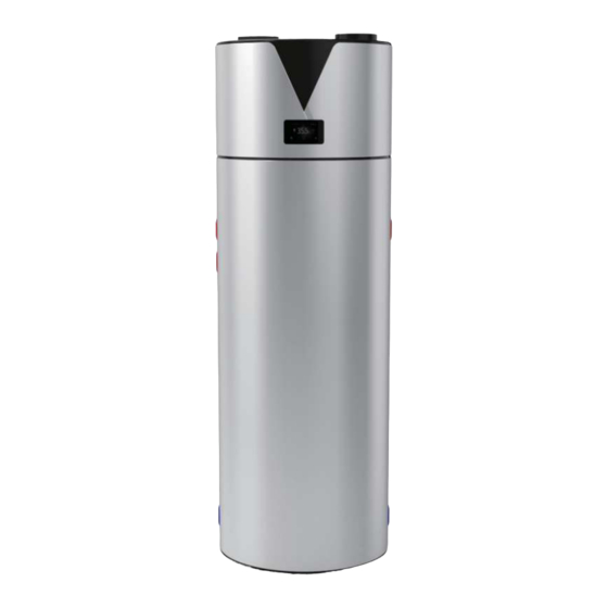
Page 9: Unit Dimension (Mm)
Unit Dimension (mm) Packing list About the Box Heat Pump Water Heater × 1 Pressure Release valve × 1... - Page 10 Dimensions Pressure Release valve Hot water outlet Magnesium Cold water Drainage inlet Unit: mm Model HPB-300(R290) HPB-200(R290) Dimensions 1905 1600 1467 1162 1208 1088...
-
Page 11: Maintenance
Maintenance WARNING: Servicing shall be performed only as recommended by the manufacturer. The local assembly should be the ones designated by manufacturer. The power cable connection should be complied with the local rules. If you need to remove or reinstall the unit, please ask the qualified person to make it to avoid improper installation which will lead to water leakage, electrical shock or fire. - Page 12 Total Hardness Dissolved Water Saturation Dissolved Chloride Solids heater CaCO3) index Co2 mg/L s mg/L (TDS) system mg/L or (Langelier) or ppm or ppm mg/L or +0.4to-1.0 2500* *For TDS levels up to and including 800mg/liter the magnesium based anode is to be used. It is recommended that magnesium anode be checked annually.
- Page 13 If any hot work is to be conducted on the refrigeration equipment or any associated parts appropriate fire extinguishing equipment shall be available to hand. Have a dry powder or CO2 fire extinguisher adjacent to the charging area 6) No ignition sources No person carrying out work in relation to a refrigeration system which involves exposing any pipe work that contains or has contained flammable refrigerant shall use any sources of ignition in such a...
- Page 14 Repair and maintenance to electrical components shall include initial safety checks and component inspection procedures. If a fault exists that could compromise safety, then no electrical supply shall be connected to the circuit until it is satisfactorily dealt with. If the fault cannot be corrected immediately but it is necessary to continue operation, an adequate temporary solution shall be used.
- Page 15 shall be at the correct rating. Replace components only with parts specified by the manufacturer. Other parts may result in the ignition of refrigerant in the atmosphere from a leak Cabling Check that cabling will not be subject to wear, corrosion, excessive pressure, vibration.
- Page 16 Purge again with inert gas; Open the circuit by cutting or brazing. The refrigerant charge shall be recovered into the correct recovery cylinders. The system shall be "flushed" with OFN to render the unit safe. This process may need to be repeated several times. Compressed air or oxygen shall not be used for this task Flushing shall be achieved by breaking the vacuum in the system with OFN and continuing to fill until the working pressure is achieved, then venting to atmosphere, and finally...
- Page 17 refrigerant cylinders: All personal protective equipment is available and being used correctly; The recovery process is supervised at all times by a competent person; Recovery equipment and cylinders conform to the appropriate standards. d) Pump down refrigerant system, if possible e) If a vacuum is not possible, make a manifold so that refrigerant can be removed from various parts of the system f) Make sure that cylinder is situated on the scales before recovery takes...
- Page 18 condition. Before using the recovery machine, check that it is in satisfactory working order, has been properly maintained and that any associated electrical components are sealed to prevent ignition in the event of a refrigerant release. Consult manufacturer if in doubt. The recovered refrigerant shall be returned to the refrigerant supplier in the correct recovery cylinder, and the relevant Waste Transfer Note arranged.
-
Page 19: Parameters
Parameters Model HPB-200(R290) HPB-300(R290) Power Supply 230V~/50Hz 230V~/50Hz Moisture Resistance IPX1 IPX1 Electrical Shockproof Heating Capacity Range Heating Power Input Range 0.41 0.41 Heating Current Input Range Auxiliary E-heater Max. Power Input Max. Current Input Refrigerant / Proper Input R290 / 150g R290 / 150g Unit Dimension(L/W/H) 640×1600... -
Page 20: Display Operation Guide
Display Operation Guide 6.1. Function of wire controller 1 Function of key Button Name Function ON/OFF Turn on/off the unit. Switch unit running modes or save setting Mode parameters. Clock Set the clock or the timer. Electric Turn on/off the electric heater or switch Heater fan modes. - Page 21 Status Name What it means icon. Shows that the unit is in heating mode. Heating Eco. heating Shows that the unit is in eco. heating mode. Vacation Shows that the unit is in vacation mode. Cooling Shows that the unit is in cooling mode Shows that the fan is on and the speed of the fan.
- Page 22 6.2. Usage of wire controller 6.2.1 Turn ON/OFF the unit Press " " and hold for 0.5s in the standby interface of the wire controller to turn on the unit and at this time the main display area shows the water outlet temperature.
- Page 24 Example: Running period 1: 8:00~10:00; Running period 2: 16:30~20:00.
- Page 25 2) In the vocation mode Press ” ” and hold for 2s to enter into the timer setting interface. The symbol ”ON ” and the date parameter are flashing at this time. Example: Set the start-up date on September 28 (Note : Turn off the unit before going out.)
- Page 26 3) If you want to cancel the timer setting, follow this below 6.2.3 Electric heater setting The electric heater can be turned on when the unit is heating or standby. Press” ” once to turn on the electric heater and press” ”...
- Page 27 6.2.4 Mode selection Press " " to select Standard heating mode, Eco heating mode, Vacation heating mode, Intelligent heating mode and High demand heating mode in power-on state and power-off state. For example:" Standard heating mode Eco heating mode We also call standard heating mode. The heat pump system will start The heat pump system will start according to the actual temperature...
- Page 28 Intelligent heating mode Vacation heating mode The heat pump automatically switches to When you select vacation mode, you economy mode, standard mode and high need to set a vacation time. The unit demand mode according to different mbient will keep operating the mode you set temperatures.
- Page 29 6.2.5 Target temperature checking and setting In the standby or running interface, press ” ” or ” ” once to check the target temperature of the outlet water. Press ” ” or ” ” again to change the target temperature. After making the changes to the parameter, press ”...
- Page 30 6.2.6 Time setting In the standby or running interface, do as follows to set the time when in heating mode. When press ” ” once, the time parameter will flash. When press ” ” again, the hour parameter will flash then press ” ”...
- Page 31 9.2.7 Fan mode setting In the main interface, long press the " " for 2S to set the fan mode.It will flash only when the fan is running, otherwise the fan blade will be static during forced ventilation; FAN MODE Definition of the fan icon : shows the fan will run at gear 1 when target setting temperature is reached.
- Page 32 :shows the fan will run at gear 3 when target setting temperature is reached. :shows the fan will run at gear 4 when target setting temperature is reached. :shows the fan will run at gear 5 when target setting temperature is reached.
-
Page 33: Failure List & Troubleshooting
Failure List & Troubleshooting 7.1. Non-error tips 1 Why the compressor is not running when I start up the unit? Answer: When the unit is powered on after the last shut-down, the compressor will not run until 3 minutes later. This is the self-protection of the unit. 2 Why sometimes the outlet water temperature on the display increases slowly? Answer Because the water temperature is different between the upper layer and bottom layer in the tank at the beginning. - Page 34 distinguishing features of the units. Normally, the heating time is 2~6 hours according to the inlet water temperature, water consumption and ambient temperature. 7.2. The normal failure and solutions For any malfunctions, please refer to the table below: Display Malfunction Description Corrective action Bottom water temp.
- Page 35 Check the connection line Communication failure (Wired remote between the wired remote control with master signal failure) control and motherboard. The water temperature is too Winter frost protection low, please pay attention to anti-freezing. Check the motor and its DC motor stalling connector.
- Page 36 CAIROX BELGIUM NV/SA Hoogstraat 180 - 1930 Zaventem - Belgium www.cairox.be Code:20221219-0001...
Need help?
Do you have a question about the R-AQUA HPB R290 and is the answer not in the manual?
Questions and answers