
Related Manuals for Nexen WEB CONTROL PA100


Summary of Contents for Nexen WEB CONTROL PA100
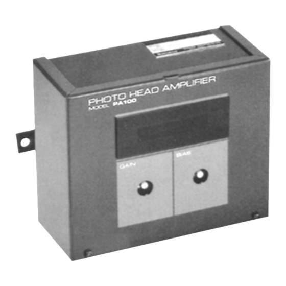
- Page 1 WEB CONTROL PRODUCTS User Manual Photo Head Amplifier System PA100 FORM NO. L-20194-B-0601...
- Page 2 In accordance with Nexen’s established policy of constant product improvement, the specifications contained in this manual are subject to change without notice. Technical data listed in this manual are based on the latest information available at the time of printing and are also subject to change without notice.
-
Page 3: Table Of Contents
TABLE OF CONTENTS Introduction ---------------------------------------------------------------------------------------------------------------------------------------- 1 Theory of Operation --------------------------------------------------------------------------------------------------------------------------- 1 Installation ---------------------------------------------------------------------------------------------------------------------------------------- 1 Electrical Connections ----------------------------------------------------------------------------------------------------------------------- 2 Calibration ----------------------------------------------------------------------------------------------------------------------------------------- 2 Maintenance -------------------------------------------------------------------------------------------------------------------------------------- 3 Specifications ------------------------------------------------------------------------------------------------------------------------------------ 3 Mounting Dimensions ------------------------------------------------------------------------------------------------------------------------- 4 Warranties ----------------------------------------------------------------------------------------------------------------------------------------- 5 (iii) -
Page 4: Introduction
Accordingly, anyone who uses a procedure that is not recommended by Nexen must first satisfy themselves that neither their safety or the safety of the product will be jeopardized by the service method selected. -
Page 5: Electrical Connections
ELECTRICAL CONNECTIONS 2. Supply 110 to 220VAC at Terminals 9 and 10, with 1. Refer to Figure 2 for electrical connections. Earth ground to Terminal 8. PHOTO HEAD + 12 VDC (11.4 to 12.6 V) Lamp Voltage 0 to + 200 mVDC (200 to 300 mV) Detection Signal Output Signal 9.5VDC to... -
Page 6: Maintenance
FIELD ADJUSTMENT WITHOUT A VOLTMETER 1. Set GAIN and BIAS Pots to midrange (See Figure 3). 2. Set POWER Switch to ON (See Figure 3). RED LEDs GREEN LED RED LEDs 3. Insert an opaque web or sample to block the light path of Photo Head, then completely remove the web or sample (See Figure 4). -
Page 7: Mounting Dimensions
MOUNTING DIMENSIONS [120] GAIN BIAS POWER [60] 2.75 [145] [70] [155] [170] [mm] FIGURE 6 FORM NO. L-20194-B-0601... -
Page 8: Warranties
Exclusive Remedy The exclusive remedy of the Buyer for any breach of the warranties set out above will be, at the sole discretion of Nexen, a repair or replacement with new, serviceably used or reconditioned Product, or issuance of credit in the amount of the purchase price paid to Nexen by the Buyer for the Products.
Need help?
Do you have a question about the WEB CONTROL PA100 and is the answer not in the manual?
Questions and answers