Table of Contents
Advertisement
Quick Links
Advertisement
Table of Contents

Related Manuals for Nexen WEB CONTROL TM140-D

Summary of Contents for Nexen WEB CONTROL TM140-D
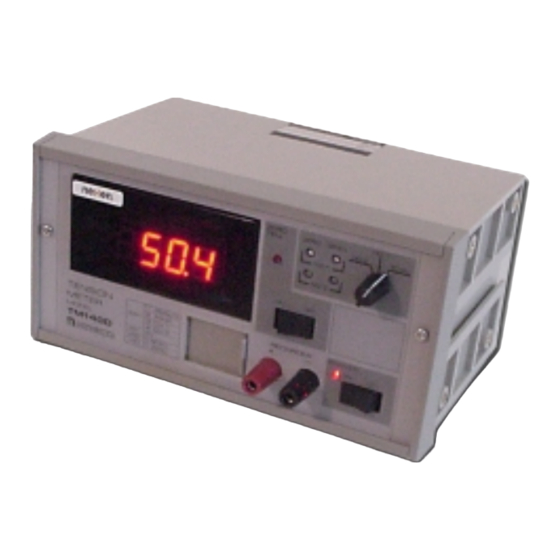
- Page 1 WEB CONTROL PRODUCTS User Manual Tension Meter TM140-D FORM NO. L-20186-B-0702...
- Page 2 In accordance with Nexen’s established policy of constant product improvement, the specifications contained in this manual are subject to change without notice. Technical data listed in this manual are based on the latest information available at the time of printing and are also subject to change without notice.
-
Page 3: Table Of Contents
ABLE OF ONTENTS Introduction --------------------------------------------------------------------------------------------------------------------------- 4 Installation ----------------------------------------------------------------------------------------------------------------------------- 5 Electrical Connections ------------------------------------------------------------------------------------------------------------ 6 Adjustment of Full Scale Value ------------------------------------------------------------------------------------------------- 7 Sensor Calibration ----------------------------------------------------------------------------------------------------------------- 7 Operation ------------------------------------------------------------------------------------------------------------------------------ 8 Maintenance -------------------------------------------------------------------------------------------------------------------------- 9 Fuse Replacement ----------------------------------------------------------------------------------------------------------------- 9 Check Terminal Values ------------------------------------------------------------------------------------------------------------ 9 Troubleshooting ------------------------------------------------------------------------------------------------------------------- 10 Mounting Dimensions ----------------------------------------------------------------------------------------------------------- 12 Specifications ---------------------------------------------------------------------------------------------------------------------- 13 Warranty ----------------------------------------------------------------------------------------------------------------------------- 14... -
Page 4: Introduction
NOTES, CAUTIONS, and These buffered signals are also present at Terminals WARNINGS are not exhaustive. Nexen can not 26, 27, and 28 located on the back panel of the possibly know or evaluate all conceivable methods in “TM140D. -
Page 5: Installation
INSTALLATION NOTE: “TM140D” is an electronic component and should be mounted in a dry, dust-free, shock and vibration-free area which has an ambient temperature of more than 32º F [0º C] and less than 122º F [50º C]. A. SHELF WALL MOUNTING 1. -
Page 6: Electrical Connections
ELECTRICAL CONNECTIONS NOTE: Use cables provided with MB Tension Sensor to connect MB Tension Sensors to External Terminals “TM140-D. ” Use 18 AWG two connector cable Green for all other connections (See Fig. 7). Yellow Tension A. SENSOR WIRING. Sensor 1. -
Page 7: Adjustment Of Full Scale Value
ADJUSTMENT OF FULL SCALE VALUE 1. Slide Adjustment Window to the left to open (See 8. Rotate VR2 until Indicator reads maximum desired Fig. 8). tension readout value. This value can be anywhere between “0” and “1999”. 2. Set Power Switch to “ON”. 9. -
Page 8: Operation
B. S DJUSTMENT 1. Thread a rope or narrow web over the sensor roll in the normal web path, making sure that the rope is in the center of the sensor roll. Hang a known weight (weight must be less than the Maximum Full Scale) on one end of the rope. -
Page 9: Maintenance
MAINTENANCE Nexen’s “TM140-D” does not require maintenance. Periodically check that the pillow block bearings mounted to the Tension Sensors have not moved. Nexen also recommends checking Zero and Span Adjustment (See Sensor Calibration) if close accuracy is required. FUSE REPLACEMENT “TM140-D”... -
Page 10: Troubleshooting
TROUBLESHOOTING START Go to “A” power supply Are the DC power supply circuit check. voltages normal? • Check voltages using the check terminal for the power supply. Is tension normally indicated Go to “B” tension when a load is applied/released sensor check. - Page 11 “B” power supply circuit check Is a voltage proportional to tension generated at check terminal CP4? Is the connector for Digital Connect to the specified Display connected to the connector. specified terminal? • AX1 is defective. • External terminal 14 and 15 are not short-circuited.
-
Page 12: Mounting Dimensions
MOUNTING DIMENSIONS Figure 14 FORM NO. L-20186-B-0702... -
Page 13: Specifications
SPECIFICATIONS Rated Torque ------------------------------------------------------------------------ 5, 10, 20, 50, 100, 200,300, 500, 1000 lbs or kg Power Supply ---------------------------------------------------------------------- 100, 110, 120, 200, 220, and 240 VAC, 50/60 Hz Ambient Temperature ---------------------------------------------------------------------------------------------- 32° to 122°F [0° to 50° C] Weight ----------------------------------------------------------------------------------------------------------------------------------- 3.3 lbs [1.5 kg] TERMINAL NUMBER OUTPUT 28--29... -
Page 14: Warranty
Buyer shall be obligated to pay or which Buyer may incur based upon, related to or arising out of its contracts with its customers or other third parties. In no event shall Nexen be liable for any amount of damages in excess of amounts paid by Buyer for Products or services as to which a breach of contract has been determined to exist.
Need help?
Do you have a question about the WEB CONTROL TM140-D and is the answer not in the manual?
Questions and answers