
Subscribe to Our Youtube Channel
Related Manuals for Eurotech INONET Concepion-hX

Summary of Contents for Eurotech INONET Concepion-hX
- Page 1 SYSTEM DOCUMENTATION Concepion -hX - 10. Gen. ® © 2023 InoNet Computer GmbH Published: 09.02.2023...
- Page 2 Table of contents General instructions Installation instructions Product description Service and support Maintenance Appendix System Documentation © InoNet Computer GmbH...
-
Page 3: Qualified Personnel
1. Notes 1.1 Notes on the documentation This documentation is intended exclusively for qualified personnel of the control and automation technology, which is familiar with the applicable standards. For the installation and commissioning of the components, it is absolutely necessary to observe the following instructions. Read the manual completely before first use and keep it in a safe place for later use. - Page 4 1. Notes © This documentation is protected by copyright. Any reproduction or third party use of this publication, in whole or in part, is prohibited without written permission. All trademarks mentioned are the property of their respective owners. Errors excepted. 1.5 Explanation of the security symbols This manual contains information that you must observe for your own safety and to avoid material damage.
-
Page 5: Installation
1. Notes 1.6 Basic safety instructions 1. Observe safety instructions Be sure to read the safety instructions before starting the operation. 2. Proper use Electronic devices are generally not fail-safe. In the event of a failure of the operating or control device or a non-disruptive power supply, the user is responsible for ensuring that connected devices, such as motors, are placed in a safe state. - Page 6 1. Notes 8. Repairs Repairs to your computer system may only be carried out by specially trained qualified personnel. Only use original spare parts and accessories for repairs. 9. Security check After servicing or repairing the product, ask the technician to perform safety checks to make sure that the product is working properly.
-
Page 7: Operating Personnel Requirements
1. Notes 1.7 Duty of care of the operator The operator must ensure that the industrial PC is only used as intended. the industrial PC is operated only in perfect working condition. the operating instructions are always in a legible state and completely ... - Page 8 2. Installation 2.1 Transport Despite the robust construction of the industrial PC, the built-in components are sensitive to heavy shocks and vibrations. Therefore, protect your systems from heavy mechanical loads during transport. Please use the original packaging for shipping. When transporting in cold environments or when the device is exposed to extreme temperature differences, ensure that no moisture (condensation, condensed water etc.) is reflected by and in the appliance.
- Page 9 2. Installation The system is to be installed professionally so that no danger (e.g. by overturning) can go out of it. There must remain a free space of at least 50 mm in the area of the ventilation slots, so that the industrial PC is adequately ventilated. 2.4 Extension/upgrading of the system Should your system be equipped with your own expansion cards, please observe the maximum power consumption as specified in the...
-
Page 10: Requirements For Commissioning
2. Installation 2.5 Setting up/installing the system When setting up the computer system, make sure that an unobstructed air flow to the cooling fins of the system is ensured. This way, optimal cooling of the PC is ensured. 2.6 Requirements for commissioning Before you switch on the system, the peripheral devices mouse, keyboard, monitor as well as the power supply must be connected. -
Page 11: Switch Off
2. Installation Now the computer runs through the power on self test. The BIOS boot message then appears on the screen. If the computer does not report on the screen, please check the cabling again and make sure that the sockets carry power. If this also does not lead to success, please refer to chapter 4.1. - Page 12 2. Installation 2.10 Decommissioning Disposal & recycling According to the EU Directive 2002/96/EC of the European Parliament and the EU Council on Waste Electrical and Electronic Equipment (WEEE) or the revised version of the EU Directive, 2012/19/EU, there is an obligation to collect waste electrical and electronic equipment, to treat it in accordance with the regulations, to dispose it and to finance this.
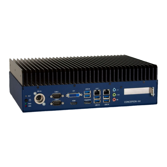
- Page 13 3. Description 3.1 Controls Control elements on the front Description Reset Button Power Button Short press (<2 sec.) in off state - operating system starts. Short press (<2 sec.) in power-on state - operating system shuts down automatically if the operating system supports shutdown via ACPI event.
- Page 14 4. Support 4.1 Troubleshooting In this chapter, you'll find tips on how to fix or isolate problems you may encounter. Causes Malfunction Measures No function of Lack of power Check the power supply cables. the computer supply to the computer The screen Screen is off Turn on the screen.
- Page 15 4. Support USB device USB ports are Other USB port or turn on the port. does not work disabled in BIOS USB 2.0/3.0 device Turn on USB 2.0/3.0. connected, although USB 2.0 is disabled Operating system No remedial action. does not support the USB interface Fan led One or more fans...
- Page 16 4. Support 4.3 Contact If a device is defective, please proceed as follows: 1. Contact us: Phone: + 49 (0)89 / 666 096-337 Fax: + 49 (0)89 / 666 096-100 E-Mail: rma@inonet.com 2. You tell us the S/N No. of the product and describe the error. 3.
- Page 17 5. Wartung 5. Maintenance In the appendix you will find an inspection and maintenance schedule. This should be continued on a regular basis. 5.1 Cleaning Turn off the industrial PC and all devices connected to it. Disconnect the system from the power supply. The system can be cleaned with a moist, soft cloth.
- Page 18 6. Appendix Inspection and maintenance schedule Last Object Type Interval Execution test on: semi- Hard disks Functional test annually BIOS Voltage check yearly battery every two Chassis Cleaning years System Documentation © InoNet Computer GmbH...
- Page 19 6. Appendix Technical data Concepion ® -hX – 10. Gen. Dimensions 306mm(W) x 230mm(D) x 90mm(H) Environmental conditions in operating condition: Temperature -10° up to 55° C Humidity 10% up to 90% non-condensing Shock 20 G, duration 11 msec. (with HDD) ...
- Page 20 6. Appendix Technical drawing System documentation © InoNet Computer GmbH...
Need help?
Do you have a question about the INONET Concepion-hX and is the answer not in the manual?
Questions and answers