Table of Contents
Advertisement
Quick Links
For product information,
Owner's Manual translations,
and more, visit
For product information,
www.MillerWelds.com
Owner's Manual translations,
and more, visit
www.MillerWelds.com
Insight Core
Insight Core
14-Pin Module CE
14-Pin Module CE
OWNER'S MANUAL
OM-260430G
OM-260430G
2021-03
2021-05
Processes
Processes
MIG (GMAW) Welding
MIG (GMAW) Welding
Pulsed MIG (GMAW-P)
Pulsed MIG (GMAW-P) Welding
Submerged Arc (SAW) Welding
Submerged Arc (SAW) Welding
Description
Description
Advanced/Automated Welding System
Advanced/Automated Welding System
™
Advertisement
Table of Contents

Subscribe to Our Youtube Channel
Related Manuals for Miller Insight Core 301072

Summary of Contents for Miller Insight Core 301072
- Page 1 OM-260430G OM-260430G 2021-03 2021-05 Processes Processes MIG (GMAW) Welding MIG (GMAW) Welding Pulsed MIG (GMAW-P) Pulsed MIG (GMAW-P) Welding Submerged Arc (SAW) Welding Submerged Arc (SAW) Welding Description Description Advanced/Automated Welding System Advanced/Automated Welding System Insight Core ™ Insight Core 14-Pin Module CE 14-Pin Module CE OWNER’S MANUAL...
- Page 2 We know you don’t have time to do it any other way. That’s why when Niels Miller first started building arc welders in 1929, he made sure his products offered long-lasting value and superior quality.
-
Page 3: Table Of Contents
TABLE OF CONTENTS SECTION 1 – SAFETY PRECAUTIONS – READ BEFORE USING..............1 Symbol Usage . - Page 4 DECLARATION OF CONFORMITY for European Community (CE marked) products. MILLER Electric Mfg. Co., 1635 Spencer Street, Appleton, WI 54914 U.S.A. declares that the product(s) identified in this declaration conform to the essential requirements and provisions of the stated Council Directive(s) and Standard(s).
-
Page 5: Section 1 - Safety Precautions - Read Before Using
SECTION 1 – SAFETY PRECAUTIONS – READ BEFORE USING Protect yourself and others from injury—read, follow, and save these important safety precautions and operating instructions. 1-1. Symbol Usage DANGER! – Indicates a hazardous situation which, if not avoided, will result in death or serious injury. The possible hazards are shown in the adjoining symbols or explained in the text. - Page 6 HOT PARTS can burn. WELDING can cause fire or explosion. � Do not touch hot parts bare handed. � Allow cooling period before working on equipment. Welding on closed containers, such as tanks, drums, or pipes, can cause them to blow up. �...
-
Page 7: Additional Hazards For Installation, Operation, And Maintenance
� Never weld on a pressurized cylinder — explosion will result. CYLINDERS can explode if � Use only correct compressed gas cylinders, regulators, hoses, damaged. and fittings designed for the specific application; maintain them Compressed gas cylinders contain gas under high and associated parts in good condition. -
Page 8: California Proposition 65 Warnings
� Have the installation regularly checked and maintained. � Be sure all equipment in the welding area is electromagnetically compatible. � Keep high-frequency source doors and panels tightly shut, keep spark gaps at correct setting, and use grounding and shielding to �... -
Page 9: Section 2 - Consignes De Sécurité - Lire Avant Utilisation
SECTION 2 – CONSIGNES DE SÉCURITÉ - LIRE AVANT UTILISATION Pour écarter les risques de blessure pour vous-même et pour autrui — lire, appliquer et ranger en lieu sûr ces consignes relatives aux précautions de sécurité et au mode opératoire. 2-1. - Page 10 � Porter un harnais de sécurité si l’on doit travailler au-dessus du � Ne pas souder des métaux munis d’un revêtement, tels que l’acier sol. galvanisé, plaqué en plomb ou au cadmium à moins que le revête- ment n’ait été enlevé dans la zone de soudure, que l’endroit soit �...
-
Page 11: Symboles De Dangers Supplémentaires En Relation Avec L'installation, Le Fonctionnement Et La Maintenance
� Ne pas couper ou souder des jantes ou des roues. Les pneus peu- Les CHAMPS vent exploser s’ils sont chauffés. Les jantes et les roues réparées ÉLECTROMAGNÉTIQUES (CEM) peuvent défaillir. Voir OSHA 29 CFR 1910.177 énuméré dans les peuvent affecter les implants normes de sécurité. - Page 12 � Suivre les consignes du Manuel des applications pour l’équation � Lorsque cela est nécessaire pour des travaux d’entretien et de dé- de levage NIOSH révisée (Publication Nº94– 110) lors du levage pannage, faire retirer les portes, panneaux, recouvrements ou dis- manuelle de pièces ou équipements lourds.
-
Page 13: Proposition Californienne 65 Avertissements
2-4. Proposition californienne 65 Avertissements AVERTISSEMENT – Ce produit peut vous exposer à des pro- Pour plus d’informations, consulter www.P65Warnings.ca.gov. duits chimiques tels que le plomb, reconnus par l’État de Californie comme cancérigènes et sources de malforma- tions ou d’autres troubles de la reproduction. 2-5. -
Page 14: Section 3 - Specifications
Information About Default Weld Parameters And Settings NOTICE – Each welding application is unique. Although certain Miller Electric products are designed to determine and default to certain typical welding parameters and settings based upon specific and relatively limited application variables input by the end user, such default settings are for reference purposes only;... -
Page 15: Environmental Specifications
NOTICE Use ONLY with compatible power sources or equipment damage may occur. Do not use with Dynasty , Maxstar , or Syncrowave power sources. • Read Owner’s Manual to check compatibility. AVIS Utiliser des sources de courant compatibles SEULEMENT, sinon un bris d'équipement pourrait survenir. -
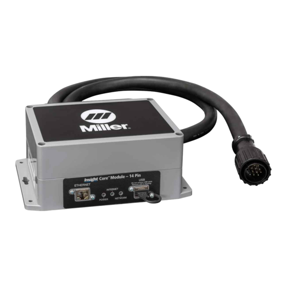
Page 16: Connections And Led Designations On Module
3-5. Connections And LED Designations On Module 3 Internet LED - Green 5 USB Port 1 Ethernet Port 4 Network LED - Yellow 2 Power LED - Green OM-260430 Page 12... -
Page 17: Mounting And Connecting Insight Core Module To Welding Power Source
3-6. Mounting And Connecting Insight Core Module To Welding Power Source Ref. 803502-A / 245855-A 4 14-Pin Control Cable From Feeder 9 Mig Gun 1 Welding Power Source 5 Positive (+) Weld Cable 10 Work Piece 2 14-Pin Insight Core Module 6 Negative (-) Weld Cable 11 Gas Cylinder And Regulator (Customer �... -
Page 18: Mounting And Connecting Insight Core Module To Subarc Digital Series W/Low Voltage Accessories
Digital/Analog require optional SubArc Digital Series to Insight Core Adaptor � Module can be mounted on either side 301295. Contact Miller Electric for as- of welding power source. sistance in selecting the proper adap- tor for your SubArc power source. - Page 19 Series controller, require 115V to 14- Pin Adapter Cord 301259. Contact � Module can be mounted on either side 6 Control Cable Miller Electric assistance of welding power source. 3 14-Pin Control Cable To Power Source 4 115VAC To 14-Pin Adapter Cord...
-
Page 20: Mounting And Connecting Insight Core Module To Subarc Ac/Dc 1000/1250 And Summit Arc 1000 Series Power Sources Using
Series controller, require 115V to 14- � Module can be mounted on either side Pin Adapter Cord 301259. Contact of welding power source. 6 Control Cable Miller Electric assistance 3 14-Pin Control Cable To Power Source 4 115VAC To 14-Pin Adapter Cord OM-260430 Page 16... -
Page 21: Section 4 - Installation
SECTION 4 – INSTALLATION 4-1. Insight Core Quick Installation Guide Step 1. Download and print Network Connectivity Survey from https://insight.millerwelds.com/download. Have form completed by IT department. Step 2. Install Insight Core Configuration Utility from https://insight.millerwelds.com/download to a PC. See Section 4-3. Step 3. -
Page 22: Downloading Connectivity Survey
4-2. Downloading Connectivity Survey To ensure proper connectivity, visit the Insight Core Download page at https://insight.millerwelds.com/download Download and print the Network Connectivity Survey Form. Ask your corporate IT department to complete the survey. 4-3. Downloading And Installing Insight Core Setup Application To A PC 1. - Page 23 3. Click Next on the Setup Wizard screen to begin installation to your computer (see Figure 4-3). Figure 4-3. Setup Wizard Screen 4. Read the End-User License Agreement and check the box to accept. Click Next to continue (see Figure 4-4). Figure 4-4.
- Page 24 5. By default, the application selects a local drive on your computer with sufficient space to install the program. Click Next to accept the default location, or change the path before proceeding (see Figure 4-5). Figure 4-5. Destination Folder 6. Click Install to complete installation of the Configuration Utility (see Figure 4-6). Figure 4-6.
- Page 25 Figure 4-7. Install Completed 9. The application is now installed on your computer. The program can be found inside All Programs in a folder named Miller Insight Core Configuration (see Figure 4-8). A shortcut is also placed on your computer’s desktop during installation.
-
Page 26: Running Configuration App For Installation Of Firmware And Connection Criteria
4-4. Running Configuration App For Installation Of Firmware And Connection Criteria � The application provides the ability to update the firmware on your Insight Core module, set the device for a wired Ethernet connection, or set it for a WiFi connection. 1. -
Page 27: Preparing Firmware For Installation
4-5. Preparing Firmware For Installation 1. Before entering connectivity information, you must first load the current revision of firmware from the download page. Click the text Click Here to display the download page if the computer is connected to the Internet. Figure 4-12. - Page 28 3. Click Browse. A dialog box opens. Figure 4-14. Browsing For Firmware Update Files 4. Locate the firmware files you downloaded previously to your computer. Click the files you plan to upgrade, placing the files inside the browse box. Click Open. Figure 4-15.
- Page 29 5. Set the number of days you want the firmware files to be valid. Options are 1 to 7 days. This setting prevents an accidental back rev of old firmware files after the timeframe has expired. Figure 4-16. Locating Latest Firmware Update Files �...
-
Page 30: Verifying Accessibility Before Connecting
Verifying Accessibility Before Connecting The Miller Insight Cloud must be accessible before the Insight Core unit will connect to a network. Using a computer in the same location and connected to the same network as the Insight Core unit will be, navigate to https://collector.millerwelds.com. -
Page 31: Configuring The Type Of Insight Core Network Connection
4-7. Configuring The Type Of Insight Core Network Connection � Determine what type of network connection Insight will use and select one of the following configurations. � To configure a wired Ethernet connection using DHCP (dynamic IP addresses), go to Section A. �... - Page 32 B. Connecting The Insight Core Module To WiFi � If WiFi Settings is selected, use the information supplied by your IT department from your Corporate Network Connectivity Survey of Re- quirements. See Section 4-2. Connection information must be applied to each unit purchased. 1.
- Page 33 E. Configuring A Wired Ethernet Connection Using A Static IP Address Per An Embedded Server Page Before proceeding with installation, confirm that your wired Ethernet line has open access to the Internet by plugging your laptop into the network C. Configuring A Wired Ethernet Connection Using A Static IP Address Per An Embedded Server Page jack using a CAT5 patch cord and browsing to a known external website.
- Page 34 If the LEDs are not illuminated and the network connection has been verified (See Section 4-6), please contact your Miller Sales If the LEDs are not illuminated and the network connection has been verified (See Section 4-11), please contact your Miller Sales representative.
- Page 35 E. Configuring A Wired Ethernet Connection Using A Static IP Address Per An Embedded Server Page D. Configuring A WiFi Connection Using A Static IP Address Per An Embedded Server Page Before proceeding with installation, confirm that your wired Ethernet line has open access to the Internet by plugging your laptop into the network jack using a CAT5 patch cord and browsing to a known external website.
- Page 36 If the Static Assigned IP address cannot be accessed, turn the power source off, insert the USB stick and power the unit on. This will write a text file to the USB stick labeled IP_MAC_LIC_ADDR.txt. Open this file using Notepad to verify the Static Assigned IP address that you are attempting to browse to is the same IP address of the Insight device as listed in the IP_MAC_LIC_ADDR.txt file.
- Page 37 MC10001Z AC1000000X1X1X00XX00X0 Figure 4-24. Insight Server Page Figure 4-27. Insight Server Page 7. Unplug the Ethernet (CAT5 or CAT6) patch cord from your PC. 8. Turn the welding power source off, and remove any USB stick if still inserted. In the WiFi Settings section, select Static for Device IP Address. 9.
-
Page 38: Firmware Update Installation
4-8. Firmware Update Installation � For help installing or running the Configuration Utility, see Section 4-3 and Section 4-4. For help locating firmware files, see Section 4-5. When firmware files are located and any additional configuration settings are made (if necessary), click Save in the Configuration window. You will be prompted to insert a USB drive. -
Page 39: Determining Device Serial Number And License Key
4-9. Determining Device Serial Number And License Key � Obtaining device serial number and license key is necessary for product registration. The USB drive used in Section 4-8 now contains a .txt file that is needed to obtain the license key. 1. -
Page 40: 4-10. Registering Initial Device And Creating An Account
4-10. Registering Initial Device And Creating An Account 1. Open a web browser and navigate to https://insight.millerwelds.com/registration. 2. Fill in all information shown in Figure 4-30. Use serial number and license key from Section 4-9. Figure 4-30. Registering A New Account 3. -
Page 41: 4-11. Registering Additional Devices
4-11. Registering Additional Devices 1. Log in to Insight Core website at https://insight.millerwelds.com. 2. Click the Configuration tab. 3. Click Register New Device. Figure 5-42. Configuration Screen Figure 4-32. Configuration Screen 4. Enter the information for the new device you intend to register. 5. -
Page 42: 4-12. Setting Up A Work Shift
2-8. Setting Up A Work Shift 4-12. Setting Up A Work Shift 2-8. Setting Up A Work Shift In order to make company settings, log in to Insight Core Website at https://insight.millerwelds.com/. � To make company settings, log in to Insight Core Website at https://insight.millerwelds.com In order to make company settings, log in to Insight Core Website at https://insight.millerwelds.com/. - Page 43 After clicking on the Save button, an Edit screen will appear to allow changes or corrections. Once the shift data is acceptable, click on the Save button (see Figure 4-4). Figure 4-4. Shift Data Edit Screen Figure 4-4. Shift Data Edit Screen Figure 4-36.
-
Page 44: 4-13. Setting Up A Group
2-9. Setting Up A Group To set up a group to organize your Insight devices into logical groups, click on the Groups tab (see Figure 4-6). 4-13. Setting Up A Group 2-9. Setting Up A Group 1. To set up a group to organize your Insight devices into logical groups, click on the Groups tab (see Figure 4-38). To set up a group to organize your Insight devices into logical groups, click on the Groups tab (see Figure 4-6). -
Page 45: Section 5 - Troubleshooting
SECTION 5 – TROUBLESHOOTING If unit does not connect to the Internet, try connecting to http://collector.millerwelds.com. If the connection is valid, a web page validating the connection will appear. See Figure 5-1. Figure 5-1. Insight Core Collector Web Page OM-260430 Page 41... -
Page 46: Section 6 - Electrical Diagrams
SECTION 6 ELECTRICAL DIAGRAM SECTION 6 – ELECTRICAL DIAGRAMS 264455-B Figure 6-1. Circuit Diagram Figure 6-1. Circuit Diagram OM-260430 Page 42 OM-260430 Page 42... -
Page 47: Section 7 - Parts List
SECTION 7 – PARTS LIST 301072 Insight Core 14-Pin Kit ™ Item No. Dia. Mkgs. Part No. Description Quantity 259221 Housing, Circuit Control 14-Pin Insight Core 264624 Assy, CCA Insight Core With Wifi 14-Pin (Includes) 264626 - Circuit Card Assy, 14-Pin Insight Core (w/Program) 263771 - Circuit Card Assy, Radio Carrier Internal Antenna 259519... - Page 48 Notes...
- Page 49 Notes...
- Page 50 Notes...
-
Page 51: Warranty
Effective January 1, 2021 (Equipment with a serial number preface of NB or newer) This limited warranty supersedes all previous Miller warranties and is exclusive with no other guarantees or warranties expressed or implied. LIMITED WARRANTY − Subject to the terms and conditions TIG Torches (No Labor) below, Miller Electric Mfg. - Page 52 Appleton, WI 54914 USA tact your distributor and/or equipment manu- facturer’s Transportation Department. International Headquarters–USA USA Phone: 920-735-4505 USA & Canada FAX: 920-735-4134 International FAX: 920-735-4125 For International Locations Visit www.MillerWelds.com ORIGINAL INSTRUCTIONS – PRINTED IN USA © Miller Electric Mfg. LLC 2021-05...
Need help?
Do you have a question about the Insight Core 301072 and is the answer not in the manual?
Questions and answers