Table of Contents
Advertisement
Quick Links
OPERATION MANUAL
RACK-AND-PINION PRESS
BASE PLATE
PRESS-ADAPTERS
Read these instructions carefully before using this tool
Art.-Nr./Order Code:
600 600 282 800 | 600 600 282 801 | 600 612 282 804 |
600 612 282 805 | 600 618 282 805 | 600 618 282 806 |
600 625 282 804 | 600 690 282 802 | 600 690 282 803 |
490 000 1
Advertisement
Table of Contents

Subscribe to Our Youtube Channel
Related Manuals for Wurth Elektronik 600 600 282 800


Summary of Contents for Wurth Elektronik 600 600 282 800
- Page 1 Read these instructions carefully before using this tool Art.-Nr./Order Code: 600 600 282 800 | 600 600 282 801 | 600 612 282 804 | 600 612 282 805 | 600 618 282 805 | 600 618 282 806 |...
- Page 2 1. Mechanical Structure 1.1 Overview Fig. 1 Handlever Stroke reducer UT Stroke stopper BDC Head unit Head locking screws Tool locking screw Screws for cover plate/bearing disc Locking screw for workpiece Cover plate for torsion spring Working stroke adjustment Frame bolt holes Locking nut –...
- Page 3 2. Setup instructions 2.1 Handlever • Mount handlever (1) to shaft and tighten it with a clamping screw. The fastening torque is from 6 Nm to max.15 Nm. Attention: The maximum operating force at the handlever is 200 N (it is not allowed to be exceeded) 2.2 Setting of working height •...
- Page 4 3. Technical Data 600 600 282 800 WR-TOOL IDC Press 600 600 282 801 WR-TOOL Base Fig. 2 Measure Value Force – 1,6 kN (360 lbs.) Stroke 0 – 40 mm (0 – 1.57 in.) Base dim. L × B 110 x 185 mm (4.33 x 7.28 in.)
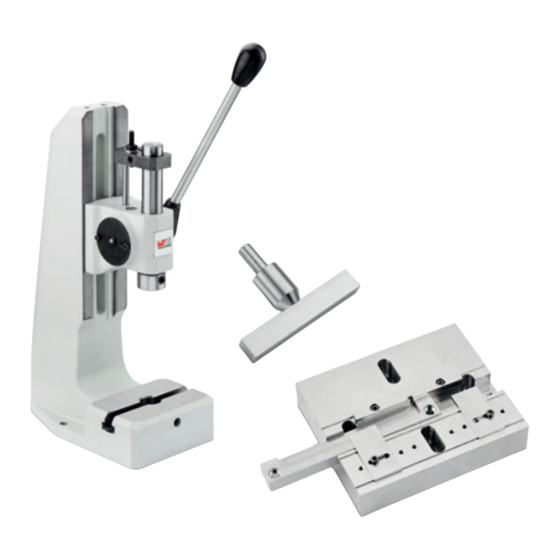
- Page 5 4. Base plate & adapters 4.1 Mounting base plate Fig. 3 • Insert base plate (a) from above into the T-slot (b) • Lock screw (c) with allen wrench until the first resistance 4.2 Available adapters Adapter no. WE-Series Fits for p/n 600 690 282 802 690 157 00x x72 WR-MM...
- Page 6 4.3 Preparatory work Fig. 4 • Unlock the screws of the baseplate (a). After that the baseplate is movable lenghtways. • Move the head unit in the lowest position • Align the fence of the baseplate (b) with the stamp (c) •...
- Page 7 4.4 Pressing process Fig. 6 • Insert the connector sideways or from above into the adapter. Make sure that the connector is placed correctly in the adapter (a) • Insert IDC connector from above into the adapter. Put the bigger plastic peg in one of the boreholes in the adapter.
- Page 8 www.we-online.com...
Need help?
Do you have a question about the 600 600 282 800 and is the answer not in the manual?
Questions and answers