Table of Contents
Advertisement
Quick Links
Advertisement
Table of Contents

Related Manuals for EKE-Electronics EKE-Trainnet DIO2908A

Summary of Contents for EKE-Electronics EKE-Trainnet DIO2908A
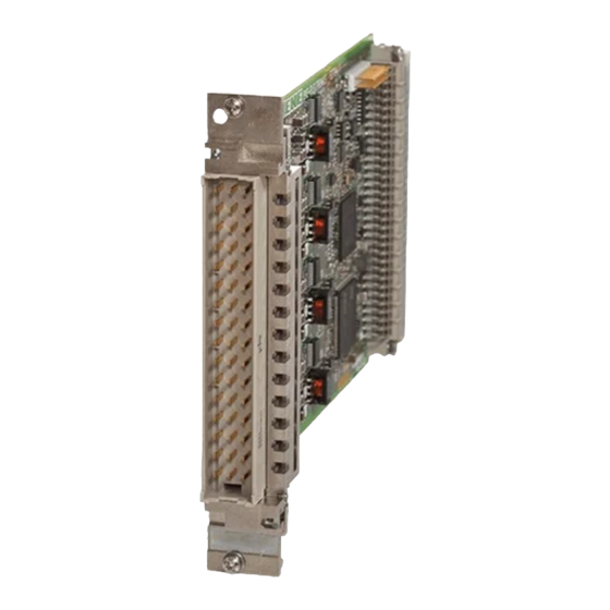
- Page 1 EKE-Trainnet® DIO2908A Digital Input Output Module DIO SIL Technical Manual...
- Page 2 The most recent information on EKE Electronics’ products and services is available at www.eke.com. Under copyright law no part of this document may be copied, reproduced or transferred electrically or manually, not even partly, without prior written permission of EKE-Electronics Ltd. This document is subject to change without notice.
-
Page 3: Table Of Contents
Insulation and voltage withstand ..............25 Environmental and EMC test specifications ..........26 EKE-Electronics Ltd. pursues a policy of continual product development. Although every effort is made to produce up-to-date product documentation this publication should not be regarded as an infallible guide to current specifications. We reserve the right to make changes without prior notice. -
Page 4: General Information
General information 1. General information This is the SIL Technical Manual for the EKE-Trainnet® DIO2908A Digital Input Output H module. This manual is for system user and for designers. This manual contains following chapters: Chapter 1: General information Chapter 2: DIO module features and operation ... -
Page 5: Symbols Used In This Manual
General information Symbols used in this manual In this manual, situations that require caution are marked with special warning symbols. The warning symbols appear in the beginning of the appropriate chapter. The following symbols are used. Figure 1.1 Electric shock warning symbol Figure 1.2 ESD warning symbol Figure 1.3... -
Page 6: Safety Considerations
Disposal of the module In order to reduce the environmental load over the product’s entire lifecycle, EKE-Electronics’ products are designed to be as safe as possible to manufacture, use, and dispose of Parts which can be recycled should always be taken to the appropriate processing centres, after hazardous waste has been removed. - Page 7 General information Table 1.1 Disposal of the DIO module, X = action, (X) = action in cases where processing is available Part Main materials Recyclable Waste disposal Hazardous waste of disposal materials sites (separate collection) Frame and covers Aluminium Metal Stainless steel Plastic PUR, PU...
-
Page 8: Dio Module Features And Operation
DIO module features and operation 2. DIO module features and operation This chapter includes information about DIO module functionality and features. Module identification DIO module features DIO module – Secure Application connection Inputs Outputs Module identification The following figure shows where to find the version and the modification information. - Page 9 DIO module features and operation Figure 2.1 The location of version and modification information A modification label shows the module modification. It is located on the back connector. The label includes letters, and the modification is indicated by crossing out one. If letter A is crossed out, the modification is A, and so on. This modification field is for the entire module.
-
Page 10: Dio Module Features
DIO module features and operation The Board test label indicates that the module has gone through the required testing cycle. It is located above the board modification field. The Board serial number identifies the module. It is located above the board test label. -
Page 11: Dio Module- Secure Application Connection
DIO module features and operation The states of inputs and readback from outputs are transmitted to the system CPU trough backplane serial link, along with diagnostic data. The states of outputs can are controlled from system CPU with a command message. DIO module has continuous self-test functionality for all channels. -
Page 12: Inputs
DIO module features and operation Figure 2.3 SA(HOST)-CPU connection Inputs The DIO has 24 input channels. In addition any number of the eight output channels can be used as a normal input when set to high impedance state. 2.4.1 Input wetting current Input load, or wetting current, is set to 20.0 mA regardless of the Group Voltage. -
Page 13: Input Self-Test
DIO module features and operation 2.4.4 Input self-test All inputs have a self-test function which use dedicated hardware controlled by firmware. Self-testing is continuous and part of the input sampling cycle. 2.4.5 Data reply message Following data is sent from DIO module to SA. Table 2.1 Data in reply message from DIO to SA Bytes... - Page 14 DIO module features and operation Module status field bits contain information about Group Voltages and various input self-test steps which can be used for diagnostic purposes. Module status is zero when everything is normal. Any non-zero value indicates an error. Table 2.2 Module status bits (for all bits, 0 is OK and 1 signals error) Contents...
-
Page 15: Outputs
DIO module features and operation Outputs The DIO has eight (8) output channels. Each can be set to high impedance state or to output the Group Voltage. The output channels are in high impedance state as a default. When set to a high impedance state an output channel can be used as an input channel. -
Page 16: Output Readback
DIO module features and operation If the bit in output mask is set and output state is set, the output is driven to high state. In high state the output voltage is the same as the Group Voltage, which is IOVCC(1) for outputs 1 to 4 and IOVCC(2) for outputs 5 to 8. - Page 17 DIO module features and operation Figure 2.4 Overload protection reaction time versus load current Measured values can slightly vary depending on the system configuration but the variation is so small that it has no impact on normal operation. The following diagram illustrates the trip current which causes the overload protection to trip in less than 10ms.
-
Page 18: Outputs At Startup
DIO module features and operation Measured values can slightly vary depending on the system configuration but 1A hold current is guaranteed over allowed operating temperature range. When overload protection activates, the output changes to high impedance (low) state and stays in that state until the cause for the short circuit is removed, either by disconnecting load or shutting off Group Voltage. -
Page 19: Installation
3. Installation This chapter includes instructions on how to install the EKE-Trainnet® DIO module into a rack. The following topics are covered in this chapter: Warnings Cable Recommendations Warnings This section contains warnings you need to consider before and during the DIO module installation. -
Page 20: Cable Recommendations
Installation Cable Recommendations 3.2.1 I/O cable The I/O cable has to have at least 0.5mm2 cross-section. In the module all IOVCC(1) internally connected to each other. The same applies to IOVCC(2) and OGND pins. This depends on the used maximum output current. The maximum current through one connector pin is 3.5A at +85°C. -
Page 21: Installing The I/O Cable On The Module
Installation Table 3.2 I/O cable assembly tools Description Manufacturer Type Crimping Tool Harting 09 99 000 0191 Insertion Tool Harting 09 99 000 0088 Removal Tool Harting 09 99 000 0087 Insertion tool for code pin Harting 09 99 000 0103 Service box Harting 09 99 000 0632... -
Page 22: Technical Data
Technical data 4. Technical data This chapter includes technical specifications of the DIO module. Table 4.1 PCB and Front panel dimensions. Dimension Value Height, 3U (128.5 mm) Width 4TE (20.32 mm) Depth 160 mm Weight 179 g Free space required in front of the module: 75 mm Non-metallic parts The following table specifies the non-metallic parts used in the DIO module. -
Page 23: I/O Connector (X1)
Technical data I/O Connector (X1) This connector is a DIN 41612 F-48 male. Table 4.3 X1 Front connector, Pin order IOVCC(2) IO8 (I32) IOVCC(2) IO7 (I31) IOVCC(2) IOGND IOGND IOVCC(2) IO6 (I30) IOVCC(2) IO5 (I29) FREQ(2) FREQ(1) IOVCC(1) IO4 (I28) IOVCC(1) IO3 (I27) IOGND... -
Page 24: Electrical Specifications
Technical data Electrical specifications The following tables specify the electrical specifications of the DIO module and the input channel. Table 4.5 Electrical specifications Parameter Specification Operating voltage 5VDC (4.75…5.25VDC) Operating current 200 mA, 500 mA max. Operating temperature - 40 ... +70 °C Group voltage: and V (two groups) -
Page 25: Reliability
Technical data Reliability Table 4.6 Reliability specifications Parameter Specification Reliability, MTBF, 1 170 000 h calculated from component FIT data at +40 °C ambient temperature greater than Safety Table 4.7 Safety Feature Reference Properties Safety Integrity Level EN 50128 SIL 2 EN 50129 SIL 2 IEC 61508... -
Page 26: Environmental And Emc Test Specifications
Technical data Environmental and EMC test specifications The following table specifies the environmental details of the DIO module. Table 4.9 Environmental specifications Parameter In conformance with Test conditions EN 50155 class TX -40... +70 ºC Operating temperature Cooling test EN 50155:2007 12.2.3 2 h at -40 °C, power off EN 60068-2-1 Ad Dry heat test...
Need help?
Do you have a question about the EKE-Trainnet DIO2908A and is the answer not in the manual?
Questions and answers