
Related Manuals for CTE TRACCESS160

Summary of Contents for CTE TRACCESS160
- Page 1 ® INSTRUCTIONS FOR USE AND MAINTENANCE MOBILE ELEVATING WORK PLATFORM FABRICATION NR......TRANSLATION OF ORIGINAL INSTRUCTIONS COD UM0313_01_US | REV. 01 | ED: 10/2021...
- Page 2 It is prohibited to reproduce, store or alteration, even partial, of this publication, without written permission by the CTE SPA. CTE S.P.A. reserves the right to make changes to the lifting platform, for any technical and commercial need, without having to update every time this publication.
- Page 3 INDEX General information Manufacturer information __________________________________________________ Limitations of responsibility _________________________________________________ Content and scope of this manual ___________________________________________ 1.3.1 Symbols ............................2 1.3.2 Illustrations .............................2 1.3.3 Scope of this manual ........................1.3.4 Amendments and additions ......................1.3.5 Composition ...........................3 1.3.6 Intended readership ........................
-
Page 4: Table Of Contents
INDEX 2.6.11 Ionising and non-ionising radiation ....................2.6.12 Lighting ............................16 Personal protective equipment (PPE) _______________________________________ 2.7.1 Harness system ...........................17 2.7.1.1 Additional personal protective equipment .................. Residual risks __________________________________________________________ Description and Technical Data General description of the machine __________________________________________ 3.1.1 Classification ..........................2 Direction _______________________________________________________________... - Page 5 INDEX 5.11 Spirit level _____________________________________________________________ 5.12 Work platform overload device ______________________________________________ 5.13 Anchorage points for the harness device _____________________________________ 5.14 Mobile console in basket monitoring device ___________________________________ Procedures for Use Foreword ______________________________________________________________ General precautions ______________________________________________________ Operating stages ________________________________________________________ 6.3.1 Pre-start checks ..........................3 6.3.2 Start-up...
- Page 6 INDEX 8.4.3 Electric pump ..........................7 8.4.4 Track tension and integrity check ....................8.4.4.1 Track tension check (Fig. 8.1, ....................8.4.4.2 Track integrity check (Fig. 8.1, ....................Lubrication and greasing _________________________________________________ 8.5.1 Greasing the pins .........................10 8.5.2 Lubricating the stabilisers ......................8.5.3 Lubricating the telescopic boom elements ...................
- Page 7 INDEX 10.1.2 Loading by lifting (Fig. 10.1, 1) ....................... 10.2 Blocking on truck or transport trailer (Fig. 10.1, 2) _______________________________ 10.3 Storage ________________________________________________________________ 11 Support and Warranty 11.1 After-Sales services and spare parts _________________________________________ 11.2 Spare parts _____________________________________________________________ 11.3 Warranty _______________________________________________________________ 12 Troubleshooting 12.1...
-
Page 8: Index
INDEX This page intentionally left blank TRACCESS 160 Aerial work platform COD. UM0313_01_US | REV. 01 | ED: 10/2021... - Page 9 Chapter 01 GENERAL INFORMATION GENERAL INFORMATION General information Manufacturer information CTE S.p.A. Via Caproni 7, Z.I. 38068 Rovereto (Trento) Italy +39 0464 485050 Phone: +39 0464 485099 Fax: Website: www.ctelift.com e-mail: info@ctelift.com Limitations of responsibility The manufacturer is responsible for the machine in its initial configuration.
- Page 10 Chapter 01 GENERAL INFORMATION • Partial or total failure to observe the machine use and maintenance instructions contained in this manual. • Use by unauthorised and/or improperly trained personnel. • Failure to observe health and safety and accident prevention legislation or the Highway Code. •...
- Page 11 The operator is directly responsible for the machine and its use. This manual does not contain instructions for maintenance operations, which must be performed only by specialised personnel or by CTE SpA authorised service centres. CAUTION Before using the machine, carefully read the manual and be sure you understand all the safety standards and operating instructions.
- Page 12 Chapter 01 GENERAL INFORMATION CHAPTER DESCRIPTION describes the structure and organisation of the manual 1 GENERAL INFORMATION and provides the manufacturer's identification data describes the safety requirements and the main safety 2 SAFETY standards to observe when using the lifting platform DESCRIPTION AND TECHNICAL contains the technical data, performance data and DATA...
- Page 13 Confidentiality The technical information (text, drawings and illustrations) contained in this manual are property of CTE S.p.A. and should be considered confidential. It is strictly prohibited to disclose, reproduce or translate this document, in whole or in part, without written authorisation from CTE S.p.A.
- Page 14 Chapter 01 GENERAL INFORMATION Glossary L i s t a n d m e a n i n g t h e m a i n t e r m s u s e d t h i s m a n u a l . TERM MEANING Lowering...
- Page 15 Chapter 01 GENERAL INFORMATION TERM MEANING Operator Person in charge of using and checking the lifting platform. An operator is defined as a person who operates, controls, moves and carries out the checks and maintenance described in this manual (excluding the work that has to be carried out by a service engineer or authorised service centre).
- Page 16 Chapter 01 GENERAL INFORMATION TERM MEANING Extending structure Structure that is connected to the chassis and work platform supports. It allows movement of the work platform to its required position. It consists of a telescopic or articulated boom or a combination thereof and may or may not slew on its base.
- Page 17 Chapter 2 SAFETY SAFETY Safety Reference standards and directives The lifting platform was designed and constructed in compliance with the following standards and directives where applicable: DIRECTIVE DATE SUBJECT DIRECTIVE 2006/42/EC OF THE EUROPEAN PARLIAMENT AND 2006/42/EC 17/05/06 COUNCIL dated 17 May 2006 relating to machinery and that modifies Directive 95/16/EC (recasting).
- Page 18 Chapter 2 SAFETY The mobile elevating work platform was built mainly referring to the standards and technical specifications shown below: STANDARD TITLE Mobile elevating work platforms - Design calculations - October UNI EN 280:2015 Stability criteria - Construction - Safety - Examinations and 2015 tests.
- Page 19 Chapter 2 SAFETY the limitations on use are described in the manual Any mode or condition of use that does not fall within the limitations of use described in this manual and not intended by the manufacturer is forbidden. DANGER! •...
- Page 20 Chapter 2 SAFETY 2.3.1 Electrocution hazard This machine is NOT electrically insulated and does NOT provide protection from contact with or when in proximity to electric power lines. Observe the minimum safety distances required by the current national regulations or, in their absence, refer to the minimum distances indicated in the table at the side (ref.
- Page 21 Chapter 2 SAFETY IT IS STRICTLY PROHIBITED TO: • Stabilise the machine on soft, muddy, frozen or slippery ground or in the immediate vicinity of holes, ditches or manholes. • Lean the platform on other machines or structures. • Exceed the maximum permissible inclination of the chassis. The maximum chassis inclination is specified in the technical specifications and on the machine plate.
- Page 22 Chapter 2 SAFETY Name of the wind Description of effects Description of effects Force at a height of 32,8 ft on land offshore above flat, open land Calm Calm, smoke rises vertically Sea like a mirror Ripples with the Direction of wind shown by appearance of scales Light air smoke drift, but not by wind...
- Page 23 Chapter 2 SAFETY 2.3.3 Risk of falling IT IS OBLIGATORY TO: • Wear suitable fall prevention devices conforming to current standards. • Attach safety harness cables to the connection provided on the work platform. • Keep the platform clear of debris. •...
- Page 24 Chapter 2 SAFETY • use the machine with insufficient lighting for the work to be carried out or for the machine moved safely. • use the machine for recreational purposes. • The lifting platform and relative electrical equipment MUST NOT be installed on surfaces that transmit vibrations and in environments where there is a danger of impact with other mechanical units.
- Page 25 Chapter 2 SAFETY Operator Definition The operators should be physically fit, in full possession of their mental faculties, fully aware of and responsible for the dangers that may arise when using the lifting platform. Physical Characteristics Operators should have good eyesight (even through the use of spectacles or contact lenses), good hearing and excellent motor skills.
- Page 26 Notification of unforeseen circumstances (such as wear, yielding, breakages, etc.) due to unforeseeable causes and therefore not dealt with in this document. Supervision of the recording of operations performed in workshops authorised by CTE. TRACCESS 160 Aerial work platform COD. UM0313_01_US| REV. 01 | ED: 10/2021...
- Page 27 Chapter 2 SAFETY Supervisor informs the operator assigned to operate the lifting platform about: (understood » the hazards present in the operating area and the hazards that may be as being the caused by the use of the lifting platform; person in charge »...
- Page 28 Chapter 2 SAFETY Road traffic This aerial work platform is fitted on a vehicle approved for road circulation. The driver should have a suitable and valid driving licence for driving the vehicle on a public road. 2.5.1 Checks and tests before driving •...
- Page 29 Chapter 2 SAFETY Safe workplace 2.6.1 Type of workplace The machine was designed and built for use in the following types of locations: • Open-air places accessible to the public (e.g. squares, car parks, public roads, etc.) • Private open-air places (e.g. yards in front of houses or blocks of flats for maintenance work on roofs etc.) •...
- Page 30 Chapter 2 SAFETY 2.6.2 Danger areas The operating envelope (A and B) of the boom when completely horizontally extended is to be considered a danger zone and as such, persons shall not be allowed to remain within it. Cordon off this area with barriers, construction site tape, chains, etc. Use appropriate signals for operations on roadworks sites.
- Page 31 Chapter 2 SAFETY 2.6.3 Risks for exposed persons The dangers caused in the situations described in the table below occur when: • The person does not respect the safety barrier and enters the danger zone • The operator forgets to delimit the boundary of the hazardous area and to affix the no entry sign in the hazardous area Cause Danger...
-
Page 32: Ionising And Non-Ionising Radiation
If the operator detects a contaminant agent that could cause the machine to malfunction, s/he must immediately call a CTE assistance centre to verify its suitability for use. 2.6.11 Ionising and non-ionising radiation The electrical equipment DOES NOT have additional protection against radiation (microwaves, ultra violet rays, laser, X-rays). -
Page 33: Personal Protective Equipment (Ppe)
Chapter 2 SAFETY Personal protective equipment (PPE) 2.7.1 Harness system OBLIGATORY All the persons occupying the work platform must wear an appropriate harness system linked to the dedicated anchorage point. The work platform is fitted with two anchorage points for the connection of a restraint system. Each anchorage point is sized for a static stress of 3 kN. -
Page 34: Additional Personal Protective Equipment
Chapter 2 SAFETY OBLIGATORY Use only devices that are well kept and in good working order. Moreover, the devices must be approved and bear the conformity CE-mark. Please refer to the manual provided by the manufacturer for the use and maintenance of the devices. -
Page 35: Description And Technical Data
Chapter 3 DESCRIPTION AND TECHNICAL DATA DESCRIPTION AND TECHNICAL DATA Description and Technical Data The technical data shown in this chapter refers to a machine with standard equipment. Any changes and/or amendments to this data because of the presence of optional equipment and/or accessories are documented in Chapter 15. -
Page 36: Classification
Chapter 3 DESCRIPTION AND TECHNICAL DATA of oil to the travel motors using the mobile control console that is fitted with proportional levers. By powering the hydraulic engine in one direction and then in the other, the minimum possible turning radius is obtained. -
Page 37: Identification Information And Ce Marking
Machine: Mobile elevating work platform (MEWP) Model: TRACCESS Type: 160 Year of construction: indicated on the CE plate CTE S.p.a. Manufacturer: Via Caproni 7, Z.I. - 38068 ROVERETO (TN) - Italy Serial plate: The serial plate illustrated below is riveted to the machine’s turret. -
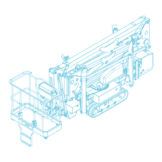
Page 38: Description Of Main Units
Chapter 3 DESCRIPTION AND TECHNICAL DATA Description of main units DESCRIPTION DESCRIPTION Main electrical panel Articulated boom (jib) lifting cylinder Combustion engine Telescopic extension Emergency controls distributor Rear stabiliser Battery Telescopic boom extension cylinder Crawler carriage Articulated boom Electric motor Front stabiliser 110V outlet Telescopic boom... -
Page 39: Main Adhesive Labels
Chapter 3 DESCRIPTION AND TECHNICAL DATA Main adhesive labels 106891US 106891US TRACCESS 160 Aerial work platform COD. UM0313_01_US | REV. 01 | ED: 10/2021... -
Page 40: Technical Specifications
Chapter 3 DESCRIPTION AND TECHNICAL DATA Technical specifications 3.6.1 Technical data sheet 550 LB (2 people and Maximum load on platform (ALL) 198 lb of equipment) Maximum platform height 44,42 ft Maximum working height 50,98 ft 22,96 ft (220 lb) Maximum outreach, edge of rail 22,96 ft (550 lb) 24,60 ft (220 lb) -
Page 41: Dimensions
Chapter 3 DESCRIPTION AND TECHNICAL DATA Dimensions The overall dimensions vary according to the engine installed on the MEWP. Please refer to the “technical features of the MEWP and inspection logbook” supplied and which is an integral part of it. Dimensions in running order (data refers to the vehicle illustrated) Length 15.18 ft... - Page 42 Chapter 3 DESCRIPTION AND TECHNICAL DATA 10.56 ft 5.28 ft 5.28 ft Fig. TRACCESS 160 Aerial work platform COD. UM0313_01_US | REV. 01 | ED: 10/2021...
- Page 43 Chapter 3 DESCRIPTION AND TECHNICAL DATA 11.08 ft 5.54 ft 5.54 ft Fig. 0.07 ft 11.82 ft 3.39 ft 15.28 ft Fig. TRACCESS 160 Aerial work platform COD. UM0313_01_US | REV. 01 | ED: 10/2021...
-
Page 44: Working Envelope
Chapter 3 DESCRIPTION AND TECHNICAL DATA Working envelope The following illustration indicates the maximum permissible load. AL BASKET Fig. TRACCESS 160 Aerial work platform COD. UM0313_01_US | REV. 01 | ED: 10/2021... -
Page 45: Controls
Chapter 4 CONTROLS CONTROLS Controls Control panels During use, the operator should only control the work platform via the mobile control console. Control station. Standing operator position. From this station, the operator can perform all the operations for Mobile control stabilising, moving and operating the machine under normal operating console: conditions. - Page 46 Chapter 4 CONTROLS Fig. Mobile control console Fig. TRACCESS 160 Aerial work platform COD. UM0313_01_US | REV. 01 | ED: 10/2021...
- Page 47 Chapter 4 CONTROLS Item Description • insert the security key to unlock the control console Security key “M-KEY” • remove the security key to lock the control console with the rotary switch (12) turned to the left: • move the control lever upwards to move the left track forwards •...
- Page 48 Chapter 4 CONTROLS with the rotary switch (12) turned to the left: • move the control lever upwards to retract the front right stabiliser • move the control lever downwards to extend the front right stabiliser Proportional control lever with the rotary switch (12) turned to the right: •...
- Page 49 Chapter 4 CONTROLS with the rotary switch (12) turned to the left: • move upwards to widen the tracks • move downwards to narrow the tracks Three-position spring-return to with the rotary switch (12) turned to the right: • centre selector switch keep the selector in the down position at the same time as using the basket rotation control (7) to centre the basket automatically;...
-
Page 50: Mobile Control Console Display
Chapter 4 CONTROLS 4.2.1 Mobile control console display Fig. Item Description • quickly flashing light when the basket is close to Red lights - overload overload • steady light when overloaded • a flashing light indicates that the turret has been centred correctly Green light - turret centring •... -
Page 51: Screen Selection Menu
Chapter 4 CONTROLS 4.2.1.1 Screen selection menu Fig. Item Description Display brightness control • Increases the brightness of the display button • Cursor up button (▲) Moves the cursor up • Cursor down button (▼) Moves the cursor down • Confirm selection button Confirms the selection •... -
Page 52: Stabilisation / Travel
Chapter 4 CONTROLS 4.2.1.2 Stabilisation / travel Fig. Item Description • green light indicates stabiliser is on the ground Stabiliser on ground light • red light indicates stabiliser is raised • indicates the longitudinal and transverse levelling of Carriage level indicator the carriage •... -
Page 53: Aerial Manoeuvres
Chapter 4 CONTROLS 4.2.1.3 Aerial manoeuvres Fig. Item Description • Red light - machine closed on indicates that the machine is closed. • Slewing ring rotation indicator indicates the rotation of the slewing ring • blue arrows indicate pantograph manoeuvres are Pantograph movement enabled •... -
Page 54: Traction Calibration
Chapter 4 CONTROLS • Basket load indicator indicates the load in the basket • Basket inclination indicator indicates the inclination of the basket • Function buttons see screen selection menu. • indicates the longitudinal and transverse levelling of Carriage level indicator the carriage •... -
Page 55: Sensor Calibration
Chapter 4 CONTROLS 4.2.1.5 Sensor calibration The calibration of the machine sensors is restricted to trained personnel. The screen is password- protected. Fig. By entering the password, you can access the screen for selecting the sensor to be calibrated Calibration can only be carried out from an active ground station. Fig. -
Page 56: Turret Control Panel
Chapter 4 CONTROLS After selecting the sensor to be calibrated, the calibration routine is activated by pressing the bypass button and the up control for the associated movement. The message SET OK appears after the calibration has been carried out. Fig. -
Page 57: Emergency Controls
Chapter 4 CONTROLS Emergency controls Fig. 4.12 Item Description Solenoid valve to rotate the turret; • tighten the upper knob to rotate the turret clockwise; • tighten the lower knob to rotate the turret anticlockwise. Solenoid valve to raise the articulated boom; •... - Page 58 Chapter 4 CONTROLS 4.13 Fig. TRACCESS 160 Aerial work platform COD. UM0313_01_US | REV. 01 | ED: 10/2021...
- Page 59 Chapter 4 CONTROLS Item Description Right rear stabiliser solenoid valve; • W2 + V34 + V31 + V22: to extend the stabiliser; • W2 + V34 + V31 + V21: to retract the stabiliser. Front right stabiliser control solenoid valve; •...
-
Page 60: Endothermic Engine Panel
Chapter 4 CONTROLS Endothermic engine panel 4.14 Fig. Item Description Low engine oil pressure light. Endothermic engine start selector: • to the left the engine shuts down; • to the right the engine starts; • resting position. WARNING To start the engine, keep the starter selector switch turned to the right. Once switched on, release the selector switch, which will automatically return to the central position. -
Page 61: Battery Disconnection Panel
Chapter 4 CONTROLS Battery disconnection panel 4.15 Fig. Item Description Circuit break selector switch; • turning the key (2) to the left breaks the electric circuit; • turning the key (2) to the right activates the electric circuit. Circuit break selector switch key. Voltage presence indicator;... -
Page 62: Electric Pump Panel
Chapter 4 CONTROLS Electric pump panel 4.16 Fig. Item Description Differential switch; • move the switch upwards to reset the electrical system. Thermal-magnetic switch; • move the switch upwards to reset the electrical system. Thermal-magnetic switch; • move the switch upwards to reset the electrical system. WARNING If the three switches are facing downwards, the electric pump will not operate;... -
Page 63: Safety Devices
Chapter 5 SAFETY DEVICES SAFETY DEVICES Safety devices Emergency stop buttons The following buttons are located in the main control stations from which the mobile working platform is operated (Fig. 5.1, 1 and 2) in order to stop the machine in the event of an emergency. Pressing the emergency button causes the: •... -
Page 64: Alarms-Warnings
Chapter 5 SAFETY DEVICES SAFETY DEVICE FUNCTIONALITY CHECK • Press the emergency button (Fig. 5.1, 1 or 2) and make sure that it is not possible to manoeuvre the platform in any way. • In order to do this under the safest possible conditions, operate the controls in the platform whilst the platform is in the stowed position. -
Page 65: Stabilisers Interlock Switch
Chapter 5 SAFETY DEVICES Stabilisers interlock switch the device (Fig. 5.2, 1) consists of a sensor on the rest and a receiver under the articulated boom (jib). It only allows the stabilisation controls to be activated when the superstructure is fully closed, the articulated boom (jib) is resting on the support and the two-position key selector switch (Fig. -
Page 66: Manual Emergency Pump
Chapter 5 SAFETY DEVICES Manual emergency pump The manual emergency pump (Fig. 5.3, 3) is installed on the frame. WARNING Only use the manual emergency pump if the main pump is broken. It is designed to manually force the circulation of the hydraulic oil in the system. To do this, insert the control lever (Fig. -
Page 67: Blocking Valves On Cylinders
Chapter 5 SAFETY DEVICES Blocking valves on cylinders The blocking valves are hydro-powered and if there is a lack of pressure (e.g. due to breakage of a delivery pipe) they prevent the uncontrolled movement of the corresponding cylinder. The on/off blocking valves (Fig. 5.5) are located: •... -
Page 68: Stabilisation Control Device
Chapter 5 SAFETY DEVICES Stabilisation control device The stabilisation control device consists of a microswitch (Fig. 5.6, 1) on each stabiliser that verifies the correct positioning of each individual stabiliser on the ground. During the stabilisation of the machine, when each stabiliser rests on the ground the respective indicator light is activated on the display of the mobile control console (Fig. -
Page 69: Platform Centring Device And Basket Centring Device
Chapter 5 SAFETY DEVICES Platform centring device and basket centring device The basket centring device consists of a proximity sensor (Fig. 5.8, 1) positioned on the basket rotation. Its function is to signal when the basket is in the centre. The platform centring device consists of an encoder (Fig. -
Page 70: Working Envelope Control Device
Chapter 5 SAFETY DEVICES 5.10 Working envelope control device The work area control device consists of two limit switches, a proximity sensor and an encoder: • one limit switch (Fig. 5.9, 1) located on the left side of the articulated boom (jib) •... - Page 71 Chapter 5 SAFETY DEVICES 5.11 Spirit level The spirit level (Fig. 5.10, 1) located on the frame, indicates if the machine is level. Fig. 5.10 SAFETY DEVICE FUNCTIONALITY CHECK • Use a hand-held spirit level to check that the spirit level on the machine is working correctly. •...
- Page 72 Chapter 5 SAFETY DEVICES 5.13 Anchorage points for the harness device The elevating platform is provided with two anchor points (Fig. 5.12, 1) for attaching the safety harnesses of the operator(s) in the basket or work platform. Operators can start working only after they have hooked up the fall-preventing personal protective equipment to the anchorage point provided on the platform.
- Page 73 Chapter 6 PROCEDURES FOR USE PROCEDURES FOR USE Procedures for Use Foreword WARNING Before reading this chapter, make sure you have carefully read and understood, ALL the previous chapters. This chapter describes the work cycle that the elevating platform can be reasonably expected to perform. Any special situations and conditions which could arise for the operators, should be dealt with taking into account and observing the machine’s maximum permitted limits (technical data) and, above all, ensuring that everything is carried out with the utmost safety for the operators firstly and, then, for...
- Page 74 Chapter 6 PROCEDURES FOR USE WARNING When using the platform, the emergency manoeuvring workstation must be monitored by qualified personnel. IT IS STRICTLY PROHIBITED TO: • lean over the edge of the platform whilst it is in use • leave the ground control station unattended while the operator is alone in the work platform. •...
- Page 75 Chapter 6 PROCEDURES FOR USE Operating stages 6.3.1 Pre-start checks WARNING You must have read and understood the operation and maintenance manual before using the platform. Only use the elevating work platform (MEWP) for the uses intended by the manufacturer and specified in this manual. The platform can only be used when stabilised on level and solid ground.
- Page 76 Chapter 6 PROCEDURES FOR USE 6.3.2 Start-up Before carrying out one of the procedures below (6.3.2.1 or 6.3.2.2) the mobile control console has to be enabled as follows: • turn the emergency stop button to the right (Fig. 6.1, 1); •...
- Page 77 Chapter 6 PROCEDURES FOR USE 6.3.2.2 Starting with electric pump WARNING Before starting the electric pump, switch off the engine by turning the selector (Fig. 6.2, 3) to the left. Procedure: • go to the front of the platform; • connect the power cable, with a minimum cross-section of 2.5x3 mm²...
- Page 78 Chapter 6 PROCEDURES FOR USE 6.3.3 Using the variable width undercarriage WARNING The carriage should be retracted with the platform stabilised in order to avoid damage to the tracks. Once this has been done, it is recommended that you extend the carriage again before moving the platform.
- Page 79 Chapter 6 PROCEDURES FOR USE 6.3.4 Platform travel 6.3.4.1 Moving the platform from the ground Procedure: • go to the left of the platform and take the mobile control console; • insert the key into the selector switch on the turret control panel (Fig. 6.4, 1) and turn it towards the left to enable the mobile control console on the ground;...
- Page 80 Chapter 6 PROCEDURES FOR USE 6.3.4.2 Moving the platform from the basket WARNING The platform can also be moved from the basket using the mobile control console as long as you make sure that the articulated boom (jib) is fully closed and the carriage extended.
- Page 81 Chapter 6 PROCEDURES FOR USE 6.3.5 Stabilising the elevating work platform (MEWP) Stabilise the platform from the ground or from the basket following the procedure below: Procedure: • Take the mobile control console; • insert the key into the selector switch on the turret control panel (Fig. 6.6, 1); turn it towards the left to enable the mobile control console if you wish to stabilise it from the ground;...
- Page 82 Chapter 6 PROCEDURES FOR USE WARNING When the indicator lights come on (Fig. 6.6, 10) it does not mean that the vehicle has been properly stabilised. This is only indicated by the spirit level (Fig. 6.6, 9). Before getting onto the platform, make sure that the machine is properly stabilised: chassis lifted and level, weight taken off the suspensions and all four stabilisers resting on suitably firm ground.
- Page 83 Chapter 6 PROCEDURES FOR USE • make sure that the light on the mobile control console has come on (Fig. 6.8, 2); • open using one of the following methods: manual opening: using the control levers, first raise the jib and consequently the articulated boom.
- Page 84 Chapter 6 PROCEDURES FOR USE WARNING It will only be possible to perform rotation manoeuvres when the jib and the articulated boom have reached the minimum position. The articulated boom may also be lowered to the ground, between the stabilisers. 6.3.7 Returning the lifting platform to its rest position Put the work platform back into its stowed position as follows (Fig.
- Page 85 Chapter 6 PROCEDURES FOR USE Fig. MANDATORY Lastly, lower the articulated boom (jib). WARNING Rotation manoeuvres will be inhibited once the articulated boom is completely closed. Only perform this manoeuvre when the platform centre position is reached. TRACCESS 160 Aerial work platform COD.
- Page 86 Chapter 6 PROCEDURES FOR USE 6.3.8 Closing the stabilisers Retract the stabilisers of the platform from the ground or basket following the procedure below: • turn the selector (Fig. 6.6, 2) on the mobile control console to the left; • make sure that all the green stabiliser indicator lights (Fig.
- Page 87 DANGER! The occurrence of the cases listed results in hazardous situations. Therefore, operators are required to stop all manoeuvres and close the platform safely and immediately contact CTE authorised repair shop to have the normal machine use conditions restored. WARNING In some set-ups, the machine is provided with optional equipment such as: Electric pumps, Electric Engines, Auxiliary Engines.
- Page 88 Chapter 7 EMERGENCY MANOEUVRES Work platform emergency stop The platform is equipped with a device that immediately stops all movements. To activate it, press one of the two red emergency stop buttons (Fig. 7.1, 1 and 2) located on the turret control panel and on the mobile control console.
- Page 89 Chapter 7 EMERGENCY MANOEUVRES Levelling the work platform WARNING If you notice that the work platform is not perfectly horizontal, lower it to the ground and get off. The work platform can be used up to a range of ± 5°. If you have to intervene manually and therefore without using the electronics, the procedure for re-levelling the platform is as follows: tighten the knob on solenoid valve V39 (Fig.
- Page 90 Chapter 7 EMERGENCY MANOEUVRES Lowering the work platform using the ground controls in the event of operator incapacity. In the event that the operator on the work platform is incapacitated, the emergency controls should be used as follows: go to the front of the platform and position yourself at the side of the main solenoid valve unit between the turret and the engine unit;...
- Page 91 Chapter 7 EMERGENCY MANOEUVRES Fig. Manual lowering of platform from the ground If the endothermic engine, the electric pump, or the gear pump that feeds all the equipment fail, or there is a power failure, the work platform can be returned as follows: go to the right of the platform and position yourself in front of the turret emergency controls (Fig.
- Page 92 Chapter 7 EMERGENCY MANOEUVRES Fig. WARNING Always press only one valve at a time. Before moving to the next valve, release the previous valve. WARNING Contact the Assistance Centre to check and repair the fault and attach a new lead wire seal onto the valves. Manual stabilisation and traction recovery If the endothermic engine, the electric pump, or the gear pump that feeds all the equipment fail, or there is a power failure, the stabilisers can be lifted and track traction performed as follows:...
- Page 93 Chapter 7 EMERGENCY MANOEUVRES • tighten the main valve V31 (Fig. 7.5, 4), tighten the proportional valve V27 (Fig. 7.5, 8A) to raise the front right stabiliser, tighten the proportional valve V28 (Fig. 7.5, 8B) to lower the front right stabiliser; press the valves corresponding to the travel movements that you wish to perform: •...
- Page 94 Chapter 7 EMERGENCY MANOEUVRES Fig. WARNING Always press only one valve at a time. Before moving to the next valve, release the previous valve. WARNING Contact the Assistance Centre to check and repair the fault and attach a new lead wire seal onto the valves. TRACCESS 160 Aerial work platform COD.
- Page 95 Chapter 8 MAINTENANCE MAINTENANCE Maintenance This chapter covers routine maintenance only. The operator can only carry out the routine maintenance indicated by “O” (operator) in the maintenance summary table Other maintenance work, indicated by “M“ (qualified technician)” in the maintenance summary table, must be carried out by qualified technicians and following the schedule and instructions indicated in the manual.
- Page 96 MAINTENANCE Inspection logbook The inspection logbook issued by CTE to the platform owner (pursuant to the meaning of Annex I to Directive 2006/42/EC) is to be considered an integral part of the machine and must accompany the machine throughout its operational life until it is scrapped.
- Page 97 Maintenance summary table CAUTION In order for the warranty to remain valid, inspection and maintenance must be carried out at an authorised CTE service centre after the first 100 hours and after every 1000 hours (or every year) of operation. 8.3.1...
- Page 98 Chapter 8 MAINTENANCE 8.3.3 Every 100 hours of operation Description of operation Section Visual inspection 6.3.1 Check use and maintenance manual 6.3.1 Legibility of plates and adhesives 6.3.1 Checking for damages and missing, loose or detached parts 6.3.1 Check welds, pins and joints 6.3.1 Check for any oil leaks Check pressures...
- Page 99 Chapter 8 MAINTENANCE 8.3.5 Yearly or every 1000 hours of operation Description of operation Section Visual inspection 6.3.1 Check use and maintenance manual 6.3.1 Legibility of plates and adhesives 6.3.1 Checking for damages and missing, loose or detached parts 6.3.1 Check welds, pins and joints 6.3.1 Check for any oil leaks...
- Page 100 Chapter 8 MAINTENANCE 8.3.6 Every 10 years or 10000 hours Description of operation Section Visual inspection 6.3.1 Check use and maintenance manual 6.3.1 Legibility of plates and adhesives 6.3.1 Checking for damages and missing, loose or detached parts 6.3.1 Check welds, pins and joints 6.3.1 Check for any oil leaks Check pressures...
- Page 101 Chapter 8 MAINTENANCE Maintenance of mechanical components 8.4.1 Main mechanisms Mechanical parts in mutual rotation should be inspected periodically, checking the condition of nuts, bolts and screws to make sure none have been loosened. Before each use, visually inspect the fixing screws and nuts connecting the slewing ring to the chassis and turret, the gearbox, the connection between the rotating joint and the turret, the locks on the pins, the fixing nuts on the vehicle, all other bolts, particularly on parts subjected to vibration and movement.
- Page 102 Chapter 8 MAINTENANCE 8.4.4 Track tension and integrity check Track tension check (Fig. 8.1, 1) 8.4.4.1 Stop the machine on solid, level ground and stabilise it. Measure the distance “A” at the central track roller from the bottom of the roller to the rigid inside of the rubber belt. The tension is correct if “A”...
- Page 103 Chapter 8 MAINTENANCE Fig. CAUTION If any of the following damage is found, contact an authorised workshop to replace the track. CAUTION In case “2” and “3” (Fig. 8.2) the towing wheel must also be replaced. TRACCESS 160 Aerial work platform COD.
- Page 104 Chapter 8 MAINTENANCE Lubrication and greasing 8.5.1 Greasing the pins Every 50 hours, grease the pins at the points specified in the figure by injecting a small amount of grease using a manual grease gun (D fig. 8.3), though the grease fittings. Lubricant: NLGI 2 grease or equivalent.
- Page 105 Chapter 8 MAINTENANCE 8.5.3 Lubricating the telescopic boom elements Lubricate every 50 hours of operation as follows: stabilise the machine and fully extend the telescopic boom. Check the lubrication of the elements. If they are dusty or dirty, clean them and remove the grease.
- Page 106 Chapter 8 MAINTENANCE Hydraulic system maintenance The hydraulic system is made up of various components that have to be maintained at different intervals. 8.6.1 Hydraulic cylinders Before each use, check that there are no leaks in the following points: rod seal, fittings, valves and pipes.
- Page 107 Chapter 8 MAINTENANCE The indicative operating environment temperature ranges for the types of oil are shown below. HYDRAULIC OIL T = TEMPERATURE (°C) ISO VG 22 -20°<T<+30° ISO VG 32 -5°<T<+40° ISO VG 46 0°<T<+50 ISO VG 68 +10°<T<+60° CAUTION The following operations should be carried out with the platform in its rest position (stabilisers and booms fully retracted).
- Page 108 Chapter 8 MAINTENANCE Fig. CAUTION Be careful not to release hydraulic oil into the environment when changing it. Dispose of the filter in accordance with the law. 8.6.7 Restore levelling of work platform CAUTION If you notice that the work platform is not level with respect to the horizontal, lower it to the ground and get off.
- Page 109 Chapter 8 MAINTENANCE After completing these operations, place both of the two-position diverting valves, back into their original position. Remove the lever from the diverting valves, put it back it in the turret and secure it using the black locking knob; attach the padlock in the locking position, close it and give the key back to the safety manager;...
- Page 110 Chapter 8 MAINTENANCE 8.6.8 Track gearbox oil level check Before each use, check the oil level in the track gearboxes. Secure the machine with the caps (Fig. 8.7, 1) at the horizontal axis. Remove the caps and check that the oil level is aligned with them. If necessary, top up from one of the two caps using the other as a level.
- Page 111 Chapter 8 MAINTENANCE Electrical system 8.7.1 Electrical circuit The electrical circuit is made up of many components. Their working efficiency should be checked according to the operations they perform. Check the working order of all operational controls before each use by carrying out a complete work cycle for each control using the ground control panel. Also check that the emergency stop buttons work properly.
- Page 112 Chapter 8 MAINTENANCE 8.7.3.1 Cell calibration procedure The user calibration procedure allows an offset (tare) to be acquired in order to zero the load reading. This is only possible if the current load value reading is between -10% and +10% of the maximum load around the original zero.
- Page 113 Chapter 8 MAINTENANCE • Wait 10 seconds until the displays switch off. • To access the calibration procedure, keep the “SW3” button pressed for at least two seconds. Two “1” digits appear on the display. • Press the “SW2” button within two seconds to enter the calibration procedure.
- Page 114 Chapter 8 MAINTENANCE Tightening the screws If you need to tighten the screws of the turret and the frame, tighten them using a manual torque wrench (Fig. 8.9, Fig. 8.10, point 1) or an electric one (Fig. 8.9, Fig. 8.10, point 2). The following tightening torques should be set when tightening, according to the screw material and thread (ISO metric thread) Nominal screw...
- Page 115 Chapter 8 MAINTENANCE 8.8.2 Tightening the frame screws Fig. 8.10 The frequency at which the screws need to be tightened depends on factors such as the frequency of use and the work environment. It is nevertheless possible to establish that under normal work conditions, the screws of the turret should be checked and tightened after the first 250 hours of operation or the first 3 months and generally least every 12 months or 1000 hours.
- Page 116 Chapter 8 MAINTENANCE Telescopic element clearance and sliding block wear verification POSITION OF PLATFORM: transport position vehicle switched off SLIDING BLOCK WEAR CHECK: The special adjustable blocks (Fig. 8.11, 1) help reduce sliding friction when the boom is extended: • check the wear and tear of the pads for the telescopic elements;...
- Page 117 Chapter 8 MAINTENANCE 8.10 Slewing ring clearance check The clearance between the slewing rings increases during the life of the slewing bearing because of wear. The amount of clearance should therefore be checked regularly. The measured values should then be compared to other measurements taken over time using an identical method. The measurement should be taken using a centesimal comparator when the turret is stationary.
- Page 118 Chapter 8 MAINTENANCE 8.11 Slewing drive greasing POSITION OF PLATFORM: transport position vehicle switched off The turntable is lubricated by injecting grease under pressure via the grease fittings using a manual or pneumatic ball couplings (Fig. 8.13, 1). The ball couplings are located on the side of the turntable; so the left side cover must be removed to gain access to them.
- Page 119 Chapter 8 MAINTENANCE 8.12 Cleaning Always keep the grip handles and footrests clean and grease-free to prevent accidental slipping and falling. It is recommended to carry out “localized” cleaning manually. Manual cleaning must be carried out using non-abrasive tools, soft cloths, brushes with soft bristles, paper, etc.
- Page 120 Chapter 8 MAINTENANCE 8.13 Paintwork inspection and maintenance Most parts and components of the lifting platform are protected from atmospheric agents by paint or other surface treatments. The paintwork should be checked regularly because if it is in good condition, it is one of the best guarantees for the platform’s long service life.
- Page 121 4010 • for all the hydraulic fittings, junction boxes, supports, pipes, heads and pins use Dinitrol 977. All work must be carried out by an authorised CTE workshop or a company specialized in surface treatment and paintwork. CAUTION Use only Corroheat 4010 Dinitrol also for all the galvanized parts including the slewing ring bolts and for all the valve blocks located under the truck bed.
- Page 122 Chapter 8 MAINTENANCE 8.14 Checking the cables and chains The wire rope and/or chain drive system should be inspected as follows. This should be carried out by an authorised workshop or a qualified technician. CAUTION This should only be carried out if the wire rope and/or chain drive systems are installed on the elevating work platform (chapter 3.6) 8.14.1 Checking the cables...
- Page 123 Chapter 8 MAINTENANCE 8.14 Fig. Tensioning the cables Make sure that the balancers are centred before carrying out the tensioning (Fig. 8.15,1). If they are not centred, do not use the platform and take it to an authorised workshop for re-tensioning. Fig.
- Page 124 Chapter 8 MAINTENANCE Lubricate chain GREASING THE MAIN BOOM: lift the boom to a max. angle of ( °) and extend the telescopic elements completely. To do this, use another platform next to the telescopic elements. GREASING THE JIB: open the JIB and fully extend its elements. To apply the lubricant: Fully extend the telescopic elements of the boom.
- Page 125 Chapter 9 DEMOLITION AND DISPOSAL DEMOLITION AND DISPOSAL Demolition and Disposal Demolition The machine should be scrapped adopting safety measures that take into account logistic and environmental factors and its state of wear. In general, it is necessary to carry out demolition following the indications below: •...
- Page 126 Chapter 9 DEMOLITION AND DISPOSAL Disposal In general, it is necessary to dispose of the machine following the indications below: • The operator must wear safety clothing and approved protective equipment (helmet, safety footwear, gloves, goggles and mask) that are compliant with the applicable safety standards •...
- Page 127 Chapter 10 TRANSPORT AND STORAGE TRANSPORT AND STORAGE Transport and storage 10.1 Loading the machine onto a vehicle • To avoid hitting low buildings, bridges or power lines when transporting the platform on a truck or trailer, you must know the exact maximum height. •...
- Page 128 Chapter 10 TRANSPORT AND STORAGE Raise: • mount the ramps and secure them with the safety pins; • control the travel of the machine following the procedure described in chapter 6 and stop it as soon as the tracks are fully on the ramps. Going down •...
- Page 129 Chapter 10 TRANSPORT AND STORAGE 10.3 Storage Short Long Machine downtime procedure term term (up to 1 month) (over 1 Month) Cleaning the machine Park the machine in a dry covered place Remove the keys of the lifting work platform (MEWP) to ...
- Page 130 Chapter 10 TRANSPORT AND STORAGE This page intentionally left blank TRACCESS 160 Aerial work platform COD. UM0313_01_US | REV. 01 | ED: 10/2021...
- Page 131 Chapter 11 SUPPORT AND WARRANTY SUPPORT AND WARRANTY Support and Warranty 11.1 After-Sales services and spare parts +39 0464 711200 Phone: +39 0464 485099 Fax: Contact your nearest authorised service centre for any extraordinary maintenance, repairs or spare parts. It will have qualified personnel and suitable equipment available for carrying out any work that may be required.
- Page 132 Chapter 11 SUPPORT AND WARRANTY 11.3 Warranty OBLIGATORY For the warranty conditions please refer to the warranty certificate delivered with the machine. The machine is covered by warranty starting from the date it is delivered to the customer. For the warranty terms and conditions, please refer to the warranty certificate delivered with the machine.
- Page 133 Chapter 12 TROUBLESHOOTING TROUBLESHOOTING Troubleshooting 12.1 Problems, causes and remedies The following pages list some of the most common issues, their probable causes and possible solutions. WARNING Certain problems may be resolved by the operator within the scope of the operations listed in the “Maintenance”...
- Page 134 Chapter 12 TROUBLESHOOTING PROBLEM CAUSE SOLUTION Worn cylinder seals Replace seals ■ Valves incorrectly The machine lifts but cannot Adjust the valves ■ adjusted support the load Jack valves dirty or Replace the valves ■ worn Vehicle inclined Stabilise the vehicle within beyond the maximum the permissible tolerance permissible flatness...
- Page 135 ■ The coil does not work Replace the coil ■ * ■ Repair to be carried out at a CTE authorised workshop WARNING For anything not described in this table, please contact the Service Centre. TRACCESS 160 Aerial work platform...
- Page 136 Safety card no ground Check the earth connections Tower card 1 no ground Check the earth connections Machine blocked Contact the CTE Assistance Centre Check AT1 rot. turret angle Saved data incorrect, recalibrate sensor AT1 rot. turret angle sensor, Check power supply and AT1 outputs; check for...
- Page 137 Chapter 12 TROUBLESHOOTING Error Description Solution REAR LEFT stabilizer extension Check power supply and sensor outputs; check for sensor in turret 1 to battery values below the minimum voltage REAR LEFT stabilizer extension Check the power and P1 outputs; check for values sensor in turret 1 to battery over the maximum voltage...
- Page 138 Chapter 12 TROUBLESHOOTING Error Description Solution A2 main boom angle sensor, V Check the power and A2 outputs; check for values battery over the maximum REAR LEFT stabilizer extension Check power supply and sensor outputs; check for sensor in turret 2 open circuit values below the minimum REAR LEFT stabilizer extension Check power supply and sensor outputs;...
- Page 139 Chapter 12 TROUBLESHOOTING Error Description Solution AT1 turret rotation sensor out of Contact the CTE Assistance Centre range L1 extension length sensor Difference between L1 and L2 > 28 cm for more inconsistent output than 1 second Difference between W1 and W2 > 20 kg for more...
- Page 140 Chapter 12 TROUBLESHOOTING Error Description Solution Basket levelling and rotation Check the Can-Bus line board 2 no can Rotation rev reading of the slewing ring with motor rotation Check the slewing ring rotation system stopped Rotation rev reading of the motor rotation with the slewing ring Check the slewing ring rotation system stopped...
- Page 141 Chapter 12 TROUBLESHOOTING Error Description Solution Check L2 extension length Saved data incorrect, recalibrate sensor L2 extension length sensor, Check power supply and L2 outputs; check for open circuit values below the minimum Extension L2 length sensor, V Check the power and L2 outputs; check for values battery over the maximum Jib sensor error at the input of...
- Page 142 Chapter 12 TROUBLESHOOTING Error Description Solution Read error - front right outrigger transducer calibration data Recalibrate (channel 1) Read error - front right outrigger transducer calibration data Recalibrate (channel 2) Read error - front left outrigger transducer calibration data Recalibrate (channel 1) Read error - front left outrigger transducer calibration data...
- Page 143 Check load cell wiring Parameters S3 not valid Check the data stored in the control unit Internal Vref error basket control Contact the CTE Assistance Centre unit 1/A Internal Vref error basket control Contact the CTE Assistance Centre unit 2/B...
- Page 144 Possible short circuit on the Check the wiring basket joystick line Operating status selection signal Contact the CTE Assistance Centre consistency error 1/A Operating status selection signal Contact the CTE Assistance Centre consistency error 2/B TRACCESS 160 Aerial work platform COD.
- Page 145 Chapter 12 TROUBLESHOOTING Error Description Solution Operating status consistency Contact the CTE Assistance Centre error 1/A Operating status consistency Contact the CTE Assistance Centre error 2/B Structural limit error Contact the CTE Assistance Centre Safety board software error Check the programming of the safety board...
- Page 146 Chapter 12 TROUBLESHOOTING Error Description Solution The selected station or function (aerial manoeuvres or stabilisation) is not allowed in the platform’s current conditions, for example: stabilisation required Station selection not valid and vehicle is not closed, or aerial manoeuvres required and vehicle is not stabilised; basket station selected and console not present in basket.
- Page 147 Chapter 13 DIAGRAMS AND ATTACHMENTS DIAGRAMS AND ATTACHMENTS Diagrams and Attachments TRACCESS 160 Aerial work platform COD. UM0313_01_US | REV. 01 | ED: 10/2021...
- Page 148 Chapter 13 DIAGRAMS AND ATTACHMENTS 13.1 Electrical sytem diagram 13.1 Fig. TRACCESS 160 Aerial work platform COD. UM0313_01_US | REV. 01 | ED: 10/2021...
- Page 149 Chapter 13 DIAGRAMS AND ATTACHMENTS 13.2 Hydraulic system diagram Fig. 13.2 TRACCESS 160 Aerial work platform COD. UM0313_01_US | REV. 01 | ED: 10/2021...
- Page 150 Chapter 13 DIAGRAMS AND ATTACHMENTS 13.3 Fig. TRACCESS 160 Aerial work platform COD. UM0313_01_US | REV. 01 | ED: 10/2021...
- Page 151 Chapter 14 FACSIMILES OF EC DECLARATION AND CERTIFICATES FACSIMILES OF EC DECLARATION Facsimiles of EC Declaration and Certificates Below is a facsimile of the EC declaration delivered with the machine and which should be kept carefully by the Customer. If it is lost, please contact Customer Services as soon as possible. +39 0464 711200 Phone: +39 0464 485099...
- Page 152 (edited according to Annex II letter A of Directive 2006/42/CE) CTE S.P.A. via Caproni 7 – Z.I. – 38068 Rovereto (TN) - ITALY, “manufacturer”, in accordance with the above directive, of the following mobile elevating work platform (machine included in Annex IV of the Machinery Directive): ...
- Page 153 Chapter 15 OPTIONAL EQUIPMENT AND ACCESSORIES OPTIONAL EQUIPMENT AND ACCESSORIES Optional equipment and accessories 15.1 Dead-man-control: pedal in the basket on the work platform The machine can be equipped with a pedal in the basket system on the work platform. This accessory, if not pressed, deactivates all manoeuvres from the control board.
- Page 154 Chapter 15 OPTIONAL EQUIPMENT AND ACCESSORIES This page intentionally left blank TRACCESS 160 Aerial work platform COD. UM0313_01_US | REV. 01 | ED: 10/2021...
- Page 155 CTE S.p.A. Headquarter and Factory Via Caproni, 7 38068 Rovereto (TN) Factory loc. Terramatta, 5 37010 Rivoli Veronese (VR) Tel. +39 0464 48.50.50 Fax +39 0464 48.50.99 info@ctelift.com www.ctelift.com...
- Page 156 CTE S.p.A. Headquarter and Factory Via Caproni, 7 38068 Rovereto (TN) Factory loc. Terramatta, 5 37010 Rivoli Veronese (VR) Tel. +39 0464 48.50.50 Fax +39 0464 48.50.99 info@ctelift.com www.ctelift.com...
Need help?
Do you have a question about the TRACCESS160 and is the answer not in the manual?
Questions and answers