
Summary of Contents for Samlex Europe RC-601D
- Page 1 REMOTE CONTROL Remote Control Model No. RC-601D Manual Please read this manual before using your remote control...
-
Page 2: Table Of Contents
CONTENT Item Dimension (Unit: mm) Installation Usage 4.1. Function 4.2. Caution 4.3. Note 4.4. Description Display Information 5.1. Real-time information 5.2. Settings 5.3. Count down timer Icon... -
Page 3: Item
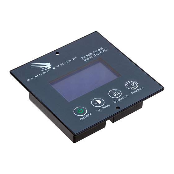
1. ITEM This product includes the following items: Remote Controller x 1 Connection Cable 10M x 1 2. DIMENSION (UNIT: MM) Front View Front View... -
Page 4: Installation
3. INSTALLATION Ensure approximately 80mm width, 72mm height and 28mm depth for the take-up of the remote controller. Connect the remote controller to the charger. The connection cable is equipped with two equivalent modular plugs. Place the remote controller into the opening created. Secure the remote controller with screws on the upper and bottom margin of the faceplate –... -
Page 5: Usage
4.3. Note The power switch at the charger must be switched ON, so that the charger can be switched ON and OFF by the RC-601D remote controller. 4.4. Description Change the... -
Page 6: Display Information
5. DISPLAY INFORMATION 5.1. Real-time information Output Voltage (V) Charger / Power Mode (Icon 1) Output Current (A) Half Mode ON / Charger OFF (Icon 2) Temperature Battery Temperature Charging Stage (Icon 3) Fan Speed (Percentage) 5.2. Settings This page displays the start-up settings, which is configured by the switches on the charger. Charger Model I/U Stage Output Voltage Uo Stage Output Voltage... -
Page 7: Count Down Timer
5. DISPLAY INFORMATION 5.3. Count down timer Absorption (Uo) Time Limit count down Equalization count down Scheduled condition count down Scheduled condition trigger count down Note: Press “Next Page” button to light up the back-light. The back-light will be off after 1 minute automatically. -
Page 8: Icon
6. ICON ICON 1 ICON 3 (Abnormal status Power Mode Charger Mode Fan abnormal ICON 2 Battery temperature too HIGH. Normal Charger voltage too HIGH. Half Power Mode Charger current too LARGE. Standby Charger output short circuit. ICON 3 Charger temperature too HIGH. Bulk Charging Stage (I) Battery reverted. - Page 9 www.samlex.com www.samlex-solar.com...
Need help?
Do you have a question about the RC-601D and is the answer not in the manual?
Questions and answers