Table of Contents
Advertisement
Quick Links
Advertisement
Table of Contents

Related Manuals for iSMA CONTROLLI FP-2B-B

Summary of Contents for iSMA CONTROLLI FP-2B-B
- Page 1 User Manual Flush Panel www.ismacontrolli.com DMP292en | 1st Issue | 02/2023...
-
Page 2: Table Of Contents
FP User Manual Table of Contents Introduction ..........................4 Revision History..........................4 Safety Rules..........................5 Technical Specification ......................6 Hardware Specification ......................7 Room Panel Version........................7 Dimensions [mm] ..........................7 Power Supply............................7 4.3.1 DC Power Connection ......................8 4.3.2 AC Power Connection.......................8 Communication..........................8 RS485 Network Termination......................9 Restoring Default Setting.......................9 Main Parameters ........................ - Page 3 FP User Manual 6.1.1 TEMPERATURE SENSOR (300) ..................... 16 6.1.2 TEMPERATURE_SENSOR_OFFSET (303)................16 6.1.3 TEMPERATURE_CONFIGURATION (315, Bit 0 and Bit 4) ..........16 Setpoint........................... 17 SETPOINT VALUE (1500) ......................17 EFFECTIVE SETPOINT (1501) ...................... 17 DEFAULT SETPOINT (1502) ......................17 OFFSET SETPOINT (1503) ......................
-
Page 4: Introduction
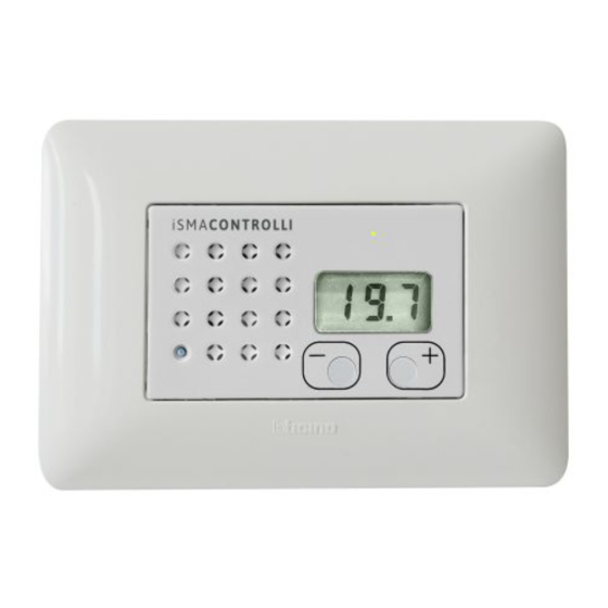
FP User Manual 1 Introduction FP is a flush panel with LCD display with four (model FP-4B-x) or two buttons (model FP-2B-x) in black and white version. The Flush Panel is powered with 24 V AC/DC and has a built-in RS485 port (Modbus RTU). The use of open communication protocol allows to connect the panel with any controller, which supports Modbus RTU/ASCII. -
Page 5: Safety Rules
FP User Manual 2 Safety Rules • Improper wiring of the product can damage it and lead to other hazards. Make sure that the product has been correctly wired before turning the power on. • Before wiring or removing/mounting the product, make sure to turn the power off. Failure to do so might cause an electric shock. -
Page 6: Technical Specification
FP User Manual 3 Technical Specification Power Supply Voltage 24 V AC/DC ± 20% Power consumption 0.2 W Temperature sensor Type 10K NTC @ 25°C (77°F) Range 0°C to 50°C (32°F to 122°F) Accuracy ± 0.5°C (± 32.9°F) Resolution ± 0.1°C (± 32.18°F) Communication 4-terminal connector 2 for power supply and 2 for the... -
Page 7: Hardware Specification
RS485 port (Modbus RTU). 4.1 Room Panel Version The FP room panels are available in the following versions: Product Code Temperatur Display Buttons Color e Sensor Black White FP-2B-B FP-2B-W FP-4B-B ... -
Page 8: Dc Power Connection
FP User Manual G0 Fase 1 / V- G Fase 2 / V+ 4.3.1 DC Power Connection Figure 3. DC power connection diagram 4.3.2 AC Power Connection Figure 4. AC power connection diagram 4.4 Communication The communication bus provides for connection to a Modbus Master device (controller). M+ ... -
Page 9: Rs485 Network Termination
FP User Manual Figure 5. RS485 Modbus connection diagram 4.5 RS485 Network Termination Transmission line effects often present a problem for data communication networks. These problems include reflections and signal attenuation. To eliminate the presence of reflections of signal from the end of the cable, the cable must be terminated at both ends with a resistor across the line adequate to its characteristic impedance. - Page 10 FP User Manual Note: in step 4 if you no longer want to load the default data, disconnect the FP sensor, reposition DIP 1 on OFF and power up again. www.ismacontrolli.com DMP292en | 1st Issue | 02/2023 page 10 of 29...
-
Page 11: Main Parameters
FP User Manual 5 Main Parameters 5.1 Communication Parameters Configuration Figure 8. Parameters configuration 5.1.1 COUNTER OF RECEIVE MESSAGE (03) The 32-bit register with the number of valid Modbus messages received by the room panel from the time of the last power-up. The value is reset after power cycle or after changing of transmission parameters (speed, stop bits, parity, etc.). -
Page 12: Parity Bit (19)
FP User Manual Value No. of Stop bit 5.1.6 PARITY BIT (19) Each byte of data being transferred may have additional protection of a parity bit added before stop bit (bits). The method of calculating parity bit determines the below table: Value Type of Parity bit None (default) -
Page 13: Device Action (0)
FP User Manual 5.2.4 DEVICE ACTION (0) Setting register 0 according to the table below enables 1 of 4 available actions: reset device, reload settings, reset settings, or enter bootloader. Register Value Decimal. Register Value Hexadecimal Action 0x01FF Reset 0x02FF Reload Setting 1023 0x03FF... -
Page 14: Led Signal
FP User Manual 5.2.8 LED Signal On the front of the sensor there is a luminous signal that represents the operating mode of the controller. Occupancy Status Led Mode Unoccupied Led Green Blink at 5% ON Standby Led OFF Occupied Led Green ON Forced Occupied Led Green Blink at 80% ON... - Page 15 FP User Manual Fan Mode Value Label LCD Fan Speed Manual 0 Manual 1 Manual 2 Manual 3 Auto 1 Auto 2 Auto 3 MODE Button From the MODE button it is possible to set the following occupation modes: Occupancy Mode Label LCD Value Unoccupied...
-
Page 16: Sensor
FP User Manual 6 Sensor In the FP room panel there is only a temperature sensor 6.1 Temperature Sensor The temperature unit is only °C 6.1.1 TEMPERATURE SENSOR (300) The register stores actual values from the temperature sensor (including Temperature Sensor Offset) multiplied by 10. -
Page 17: Setpoint
FP User Manual 7 Setpoint This section outlines the registers for setpoints configuration. 7.1 SETPOINT VALUE (1500) The register stores an actual setpoint value multiplied by 10. After device restart, the value is read from the DEFAULT_SETPOINT_VALUE register and set as the actual setpoint value. -
Page 18: Configuration
FP User Manual 7.8 CONFIGURATION 7.8.1 SETPOINT CONFIGURATION (1512) SETPOINT_VISIBILITY (1512, Bit 0) The bit 0 is responsible for activation or deactivation of the setpoint visibility. If the bit 0 is active, the setpoint actual value is displayed in the main menu. By default, the bit 0 is true (setpoint is visible). - Page 19 FP User Manual lower than negative value OFFSET_RANGE register, actual OFFSET_SETPOINT value is overwritten by the value in that register. www.ismacontrolli.com DMP292en | 1st Issue | 02/2023 page 19 of 29...
-
Page 20: Fan
FP User Manual 8 Fan The FP room panel allows fan control from the dedicated FAN button and LCD display. The fan configuration registers allow to select different fan control modes, corresponding to different fan types. The user can switch different FAN Mode pushing dedicate button and see the actual State on LCD. -
Page 21: Fan Type (1602)
FP User Manual 8.3 FAN TYPE (1602) The register contains numeric values corresponding to the fan type. The fan type selection determines which fan modes are available in the FAN_MODE register. This register has a software limitation, where the max. value is 6. Available fan modes in particular fan type selection are shown in the table below: Fan Type Available Fan Mode... - Page 22 FP User Manual Local Mode: If the bit 6 is true, the room panel fan setting works in a local mode. It means that the value of the FAN_CURRENT_SPEED register is determined by the value of the FAN_MODE register and so the value of the FAN_CURRENT_SPEED register cannot be overwritten by the higher level system.
-
Page 23: Occupancy
FP User Manual 9 Occupancy Setting of the Occupancy Mode is available from Mode Button The FP room panel allows Occupancy Mode control from the dedicated MODE button. The Mode configuration registers allow to select different Occupancy Mode control modes. The user can switch different Occupancy Mode pushing dedicate button and see the actual State on LCD display and Status Led. -
Page 24: Configuration
FP User Manual 9.3 Configuration 9.3.1 OCCUPANCY CONFIGURATION (1706) OCCUPANCY_VISIBILITY (1706, Bit 0) The bit 0 of the register 1706 is responsible for activation or deactivation of the occupancy current status visibility. If the bit 0 is active, the occupancy current status is visible on LCD display. -
Page 25: Register Adjustable Locally From Room Panel
FP User Manual 10 Register Adjustable Locally from Room Panel 10.1 Room Panel Setting The additional parameters that can be managed are: • FP sensor Modbus Address (LCD label “Add”). • NTC temperature reading calibration (LCD label “tAr”). • FP sensor FW release (LCD label “rEl). It is read-only. Figure 10. -
Page 26: List Of Modbus Register
FP User Manual 11 List of Modbus Register Modbus Decimal Register Access Description Address Address Address name 41501 1500 0X05DC SetPoint Actual Stpoint 31502 1501 0X05DD Effective Effective SetPoint: if use CorrSet SetPoint 30301 0X012C Temperature Actual Temperature Sensor + correction (TarProbe) 41505 1504... - Page 27 FP User Manual Modbus Decimal Register Access Description Address Address Address name 31303 1302 0X0516 Boot Version Defined in BootLoader 31304 1303 0X0517 FW Version Defined to FW 31305 1304 0X0518 Serial number Part 1/4 31306 1305 0X0519 Serial number Part 2/4 31307 1306...
- Page 28 FP User Manual Modbus Decimal Register Access Description Address Address Address name 41601 1600 0X0640 FanStatus Current StatusFan Speed send from FCU 41602 1601 0X0641 FanMode Fan Mode 1, 2, 3, Auto 41603 1602 0X0642 FanType Fan Type 0-10V , 1 Speed, 2 Speed, 3 Speed , 1 Speed+ Auto, 2 Speed+ Auto, 3 Speed+ Auto 41614...
- Page 29 FP User Manual Modbus Decimal Register Access Description Address Address Address name Bit 4 - Third Not Active Active (def) Point Decimal Bit 5 - -- Not Used Not Used 40029 0X01C TypeSensor iSMA-RT only temperature (always 0x04) 40023 0X016 MBAddress Modbus Address RT Probe 40018...
Need help?
Do you have a question about the FP-2B-B and is the answer not in the manual?
Questions and answers