Table of Contents
Advertisement
Quick Links
Advertisement
Table of Contents

Subscribe to Our Youtube Channel
Related Manuals for CS Instruments VA 500


Summary of Contents for CS Instruments VA 500
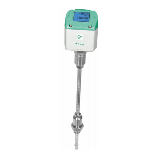
- Page 1 MOUNTING INSTRUCTION High pressure rig VA 500 V1.02...
- Page 2 The device is destined exclusively for the described application. CS Instruments GmbH & Co.KG offers no guarantee for the suitability for any other purpose and is not liable for errors which may have slipped into this operation manual. CS Instru- ments GmbH is also not liable for consequential damage resulting from the delivery, capabi- lity or use of this device.
- Page 3 Insert the upper plate (3) which has not been fixed yet with its notch into the slot below the sensor head. • Connect the flexible mounting thread of the sensor VA 500 gas-tightly to the ball valve. Attention: Sensor tip is not allowed to touch the ball of the ball valve.
- Page 4 ASSIGNMENT OF THE ITEMS V1.02...
- Page 5 LIST OF ITEMS Position Quantity Designation of the itme Ball valve G1/2“, threepart, made of stainless-steel Fastening plate Upper plate Thread bars Guide bars Wing nuts Fastening nuts and washers A = Counter nuts ALIGNMENT OF THE SENSOR Safety information must be observed. Assembly is carried out by inserting the connection thread (1/2“...
- Page 6 CONTACT Sales office SOUTH Germany Zindelsteiner Str. 15 D-78052 Villingen-Schwenningen Phone +49 (0) 7705 97 89 9-0 Fax +49 (0) 7705 97 89 9-20 info@cs-instruments.com www.cs-instruments.com Sales office NORTH Germany Gewerbehof 14 D-24955 Harrislee Phone +49 (0) 461 700 20 25 Fax +49 (0) 461 700 20 26 info@cs-instruments.com www.cs-instruments.com...
Need help?
Do you have a question about the VA 500 and is the answer not in the manual?
Questions and answers