
Related Manuals for MBO T700


Summary of Contents for MBO T700
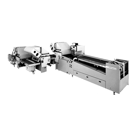
- Page 1 Buckle Folding Machines Original operating manual T700/T800.1 Continuous Feeder Preserve for future appliance...
-
Page 2: Table Of Contents
Operating manual T700/T800.1 - en Contents Prologue..........................6 1.0 Specifications ......................6 1.1 Manufacturer ......................6 1.2 Type ..........................6 1.3 Technical data ......................7 1.3.1 Sizes ..............................7 1.3.2 Electrical data ........................... 7 1.3.3 Speed ............................... 7 1.3.4 Weights in kg ............................. 7 1.3.5 Floor plan ............................ - Page 3 Operating manual T700/T800.1 - en 3.0 Transportation/Erection/Installation ..............18 3.1 Transportation ......................18 3.1.1 Folding unit I ............................ 18 3.1.2 Feeder ............................. 19 3.1.3 Folding units II and III ........................19 3.1.4 Cleaning ............................19 3.2 Erection/Installation of machine ................2 0 3.2.1 Folding unit I ...........................
- Page 4 Operating manual T700/T800.1 - en 5.2 Main control panels (Options) ................41 5.2.1 Push button control ......................... 41 5.2.2 Rapidset ............................42 5.3 Feeder ........................4 3 5.3.1 Upper pile table..........................43 5.3.2 Drum ............................... 44 5.3.3 Lower table ............................. 45 5.3.4 Transport control ..........................
- Page 5 Operating manual T700/T800.1 - en 5.8 Noise damping device (option) ................8 2 6.0 Instructions to the user ..................8 3 6.1 Setting instruction for the most commonly folds ..........8 3 6.1.1 Parallelfold ............................83 P 1 1 x parallel fold, i.e. 4 pages ......................83 P 2 2 x parallel fold, i.e.
-
Page 6: Prologue
T700/T800.1 - en Prologue With the MBO folding machine you have purchased a valuable product. However, it is absolutely imperative to comply with all Safety Regulations and Safety Instructions. This Operating Manual should also instruct you to correctly operate the MBO folding machine and to comply with the Safety Regulations and to maintain the machine properly. -
Page 7: Technical Data
Operating manual T700/T800.1 - en Technical data 1.3.1 Sizes T 700 T 800.1 Maximum sheet size: 69 x 130 cm (200) cm (26 x 39 ½”) 78 x 130 cm (200 cm)(30 x 42 ½”) Minimum sheet sizes: 15 x 18 cm (6 x 8 ”) 15 x 18 cm (6 x 8 ”) -
Page 8: Floor Plan
Operating manual T700/T800.1 - en 1.3.5 Floor plan (measurements in cms): T 700 T 800.1 Alterations reserved Seite 8 Stand 05/2008... -
Page 9: 1.4 Documentation
Operating manual T700/T800.1 - en 1.4 Documentation: Customer: Machine configuration: Machine-/Serial No.: Type of feeder: Continuous feeder Type of pump: Electrical data: Wiring diagram no.: Folding unit: Feeder: Delivery: Operating voltage (V/Hz): Control voltage (V/A): Control voltage (V/A): Total rated current (A):... -
Page 10: Supplementary Documents
Operating manual T700/T800.1 - en Supplementary Documents: Operating Manual batch counter: air pump: auxiliary units: auxiliary units: other manufacturers: Spare parts lists machine: feeder: pump: peripherical units: other manufacturers: Knife list: TM 32/2 Alterations reserved Seite 10 Stand 05/2008... -
Page 11: Information To User/Functioning Description
Additional buckle plate units II, III, and IV, mobile knife folding units, such as Z 2, Z 5, and Z 6, special folding units or various other MBO deliveries may be attached, if necessary. Standard buckle folding units consist of two, four or six buckle plates with swing deflectors, spiral foldrollers which can be adjusted through quick setting elements on the side frame of the machine, and quickly removeable slitter shafts with plug bearings. -
Page 12: Buckle Fold
Operating manual T700/T800.1 - en Buckle fold: The principle of buckle fold is that the sheet is always pushed into the buckle plate. Three foldrollers and one buckle plate are necessary to prepare a buckle fold. Foldrollers 1 and 2 carry the sheet into the buckle plate 4 to the sheet stop. -
Page 13: Basic Safety Instructions
Safety at working place - destined use of the folding machine 2.2.1 MBO folding machines correspond to their stipulated Safety Technical Requirement at the time of their shipment. Therefore, any moveable and rotating parts are covered with protective hoods and are mechanically and electrically interlocked to such an extent as to not unreasonably detract from the operation. - Page 14 Operating manual T700/T800.1 - en 2.2.10 Never use any tools which are not in a perfect condition and make sure that no tools are left on the machine after completion of settings and maintenance. Tools which fall into the machine may cause serious injuries and damages.
-
Page 15: Safety Devices - Machine
Operating manual T700/T800.1 - en Safety devices - machine 2.3.1 Protective hoods - Checklist of parallel unit/feeder and mobile folding units Alterations reserved Seite 15 Stand 05/2008... -
Page 16: Protective Hoods - Chart Of Parallel Unit And Feeder
Operating manual T700/T800.1 - en 2.3.2 Protective hoods - Chart of parallel unit and feeder Alterations reserved Seite 16 Stand 05/2008... -
Page 17: Protective Hoods - Chart Of Mobile Folding Units
Operating manual T700/T800.1 - en 2.3.3 Protective hoods - Chart of mobile folding units Alterations reserved Seite 17 Stand 05/2008... -
Page 18: Transportation/Erection/Installation
Operating manual T700/T800.1 - en Transportation/Erection/Installation This part of the Operating Manual is directed to the competent service personnel and internal authorized personnel. Transportation Folding units, feeder and delivery are delivered in separate crates. Move them to their final destination as close as possible. -
Page 19: Feeder
Operating manual T700/T800.1 - en 3.1.2 Feeder Unscrew the feeder off the pallet and lift it with a forklift at positions 1 and 2 and carry it to its final destination. > ATTENTION < Make sure that flap 3 as well as air tubes and valves behind it are not damaged! >... -
Page 20: Erection/Installation Of Machine
Operating manual T700/T800.1 - en Erection/Installation of machine 3.2.1 Folding unit I > DANGER < The unit may fall or slip off! Therefore, brace the unit, accordingly! Carry the folding unit to its final position. Place plastic feets 2 underneath the setting screws 1. -
Page 21: Feeder
Operating manual T700/T800.1 - en 3.2.2 Feeder Place the feeder onto the levelling screws and plastic feets 1 and move it to the folding unit. Alignment holes of register table 2 and feeder 3 must correspond with eachother. Exact position has been marked by the factory. -
Page 22: Pressure-/Vacuum Pump
Operating manual T700/T800.1 - en 3.2.3 Pressure-/vacuum pump The pump has been installed under the feeder table by the manufacturer, as well as all pressure and vacuum tubes. Affix noise reducer 1. > ATTENTION < Check the rotating field. If this is not correct it may cause essential damage to the pressure-/vacuum pump. -
Page 23: Noise Damping Hoods (Optional)
Operating manual T700/T800.1 - en 3.2.5 Noise damping hoods (optional) Noise hoods 1 and 2 are installed by the manufacturer. 3.2.6 Guard above the slitter shafts > DANGER < Check of the safety switch 1: If the guard 2 is lifted the safety switch 1 must activate. -
Page 24: Guards
Operating manual T700/T800.1 - en 3.2.7 Guards > DANGER < Use and affix all protective hoods which have been delivered with! Fasten the noise hood 1 under the register table with four screws 2. Hook-in the door 3 with the tool drawer. -
Page 25: Electrical Connection
Operating manual T700/T800.1 - en Electrical connection > DANGER - MAY BE HAZARDOUS TO YOUR LIFE < These works are only to be carried out by authorized or skilled personnel! 3.3.1 Installation of main control panel Fasten the holder 1 with five screws 2 at first, then affix 4 the main control panel 3 onto holder 1. -
Page 26: Mcc Counter
Operating manual T700/T800.1 - en 3.3.2 MCC Counter Open the front plate 1 and remove cover plate at rear side of counter 2. Pull the cable out of opening 3 and push it through the opening 4 into 2. Place 2 onto the adapter 5. -
Page 27: Main Power Connection
Operating manual T700/T800.1 - en 3.3.3 Main Power Connection > DANGER - MAY BE HAZARDOUS TO YOUR LIFE < These works are only to be carried out by authorized or skilled personnel! > ATTENTION < Check whether the supply voltage and frequency correspond to the data indicated on the machine label 3. -
Page 28: Maintenance
Operating manual T700/T800.1 - en Maintenance This part is directed to the competent service personnel or internal authorized personnel. > DANGER < No cleanings nor maintenance works should be carried out unless the electrical supply is isolated. Always turn OFF the isolator on the control cabinett and secure it with a safety lock ! >... -
Page 29: Exchange And/Or Tensioning Of Belts/Tapes
Operating manual T700/T800.1 - en Exchange and/or tensioning of belts/tapes 4.1.1 Register belt at register table Loosen the screw 1 and release tension of register belt 2 through screws 3. Unhinge the lattice-type alignment table at 4. Loosen the screw 5 and remove rod 6. -
Page 30: Drive Belt For Suction Wheel/Vacu-Infeed
Operating manual T700/T800.1 - en 4.1.2 Drive belt for suction wheel/Vacu-Infeed Tension the drive belt 1 through tensioning lever 2. Exchange: Remove guard 3, open 5 the coupling 4 and re-thread the tape. The installation occurs in the opposite sequence. -
Page 31: Drive Tape For Foldrollers And Slitter Shafts At Parallel Unit
Operating manual T700/T800.1 - en 4.1.4 Drive tape for foldrollers and slitter shafts at parallel unit The drive belt 1 is automatically tensioned by draw spring 2. Do not use the adjustment screw 3 for belt tensioning. It should be approximately 1 mm underneath the tensioning lever 4 if machine is stopped. -
Page 32: Drive Belt For Register Table On Mobile Folding Units
Operating manual T700/T800.1 - en 4.1.6 Drive belt for register table on mobile folding units Strain tightening of the drive belt 1 at bottom side of register table: Loosen the screws 2 and 3, insert screw 4 from the external side through the opening 5. -
Page 33: Feeder - Upper Transport Tape
Operating manual T700/T800.1 - en 4.1.8 Feeder - upper transport tape The transport tape 1 must be tightened properly to ensure trouble-free sheet transportation. Screw-in both screws 2 equally at both sides! 4.1.9 Feeder - Lower transport tapes Both transport tapes 1... -
Page 34: Lubrication / Cleaning
Operating manual T700/T800.1 - en Lubrication / Cleaning > NOTICE < Generally, the machine should be cleaned after each job, particularly moveable parts which have been changed due to change of sheet size, because heavy dust may cause reduction of function. -
Page 35: Folding Units
Operating manual T700/T800.1 - en 4.2.3 Folding units Provide a slight touch of oil between the machine frame and bearing lever 1 at both sides of the machine monthly. 4.2.4 Cleaning roller The cleaning roller 1 under the flap 2 is stripping off the powder of the upper foldroller. -
Page 36: 4.2.5 Cleaning Of Foldrollers
Please contact your machine supplier. Improper cleaner may cause decomposure or swelling of the foldroller coating. MBO the manufacturer of this folding machine recommends a cleaning material for the foldrollers made by VARN, bearing the no. VARN-Wash VM 111 or VWM. Our recommendation is on a label near the foldrollers. -
Page 37: Pressure/Vacuum Pump
Operating manual T700/T800.1 - en 4.2.6 Pressure/Vacuum Pump The cleaning of the pump depends on the use of the folding machine. It may become necessary weekly or at infrequent intervals. Please check separate Operating Manual of manufacturer. > NOTICE < To ensure full efficiency, however, the cartridge at suction side should be checked and cleaned occasionally. - Page 38 Operating manual T700/T800.1 - en Continuation Filter - air blast Open the clips 3 and remove the caps 4 as well as the filtre cartridges 5. And clean them by blowing through from the internal to the external side. Exchange cartridge every six months.
-
Page 39: Maintenance Report
Operating manual T700/T800.1 - en 4.2.7 Maintenance Report This page may be attached to the Maintenance and Check List with the machine, whereby all items described under para. 4.2 should be considered! Alterations reserved Seite 39 Stand 05/2008... -
Page 40: Operation Of The Machine
Operating manual T700/T800.1 - en Operation of the machine Main control panel - Standard control ”MC” MAIN SWITCH ON/OFF switch for AIR PUMP Red mushroom button with locking for EMERGENCY STOP Button to STOP the machine Button to START the machine... -
Page 41: Main Control Panels (Options)
Operating manual T700/T800.1 - en Main control panels (Options) 5.2.1 Push button control MAIN SWITCH ON/OFF switch for AIR PUMP Red mushroom button with locking for EMERGENCY STOP Button to STOP the machine Button to START the machine Button for SHEET INFEED during PRODUCTION and feeder START/STOP... -
Page 42: Rapidset
Operating manual T700/T800.1 - en 5.2.2 Rapidset MAIN SWITCH ON/OFF switch for AIR PUMP Red mushroom button with locking for EMERGENCY STOP Button to STOP the machine Button to START the machine Potentiometre for electronic speed control Button for SHEET INFEED during PRODUCTION and feeder START/STOP... -
Page 43: Feeder
Operating manual T700/T800.1 - en Feeder 5.3.1 Upper pile table Set the lateral sheet stop 1 with knurled grips 2 to ½ of sheet width; use mm-scale 3. For pile transportation ON/OFF: Use blue button 4 at feeder table or blue push button at main control panel 7. -
Page 44: Drum
Operating manual T700/T800.1 - en 5.3.2 Drum Set the roller chains 1 and long Teflon tapes 2 in accordance with the sheet size: Distance of Teflon tapes 2 to the paper edge should be approx. 2 cm; mediate the roller chains 1. -
Page 45: Lower Table
Operating manual T700/T800.1 - en 5.3.3 Lower table Use the guide plate 1 and pin 2 for exact positioning of the paper. > NOTICE < Jam will occur if sheets are pinched! For safe sheet separation set the rollers 3 and brush 4 to the end of approx. -
Page 46: Transport Control
Operating manual T700/T800.1 - en 5.3.4 Transport control The transportation of feeder is controlled through feeler tongue 1 and sensor 2. The feeler tongue 1 is resting at sensor 2 if no sheets are processed; for turn ON of feeder see para. - Page 47 Operating manual T700/T800.1 - en Continuation Set the infeed plate 1 with knurled grip 2 higher/lower and fix it through the knurled screw 3. For sheets which tend to roll down = move the infeed plate 1 up. For sheets which tend to roll up = move the infeed plate 1 down.
-
Page 48: Areation/Air Support
Operating manual T700/T800.1 - en 5.3.5 Areation/air support Air blast support through air pump. Vacuum air support through separate vacuum pump. Both pumps can be turned ON/OFF through switch 2 at main control panel. Air tube 1 with nozzles 2 may be opened or closed through the clips 3. - Page 49 Operating manual T700/T800.1 - en Continuation Regulate the quantity of air blast through valves 7 for the operator side and 8 for the drive side. Approximately 10 - 15 sheets on top of pile should be areated. Use smoothers 9 and 10...
- Page 50 Operating manual T700/T800.1 - en Continuation The positioning of side blower 12 at operator side into length- and crosswise direction occurs through holder 14. Set the balance through the weight 15 to such an extend that the side blower 12 is slightly touching the sheet;...
-
Page 51: Vacu-Infeed (Option)
Operating manual T700/T800.1 - en 5.3.6 Suction wheel The suction wheel 1 is carrying the sheets onto the register table 2. Point of suction 3 should be on the lowest position of the suction wheel; set lever 4 into vertical position. -
Page 52: Register Table
Operating manual T700/T800.1 - en Register table 5.4.1 Ball rail (standard) Set the sidelay 1 through the knurled grip 2 to 1/2 of sheet width at mm-scale. Fine adjustments should be made through knurled grip 3. Set the guide plate as well as the rail 4 above it so as to control the outside edge of the transported sheet. -
Page 53: Vacu-Alignment (Option)
Operating manual T700/T800.1 - en 5.4.2 Vacu-Alignment (Option) The Vacu-Alignment 1 has a separate vacuum pump 3. ON/OFF position also occurs through switch 2. Heavy or thick paper require more vacuum than light or thin paper. The setting occurs at twist-grip 4, scale +/- For safe transfer at infeed heavy or oblong sheets require more vacuum at vacuum roller 5. -
Page 54: Double Sheet Control
Operating manual T700/T800.1 - en 5.4.3 Double sheet control Press the lever 1 and insert a paper strip (which you are running) into the gap 2 between the bolt 3 and the knurled screw 4. Insert a double paper strip under the segment 5. Turn the knurled screw 4 until the segment 5 has switched and tighten the knurled nut 6 after the adjustment of the double sheet control has been completed. -
Page 55: Sheet Infeed Control
Operating manual T700/T800.1 - en Sheet infeed control 5.5.1 Automatic learning of suction length and sheet gap START the machine 1 and turn ON the pump 2. Keep the button SUCTION LENGTH 3 pushed and activate the SINGLE SHEET 4 button. A „ learning „ sheet is entered with a basic suction length. -
Page 56: Photocells (Standard)
Operating manual T700/T800.1 - en 5.5.2 Photocells (Standard) Photocell 1 controls the sheet infeed at suction wheel / the Vacubelt and is counting the infeeded sheets. Photocell 2 controls the infeed of parallel unit and calculates the sheet or suction length. -
Page 57: Photocells In Folding Units Ii And Iii (Option)
Operating manual T700/T800.1 - en 5.5.3 Photocells in folding units II and III (option) In addition to the standard design (5.5.2) the following items are available: Photocell 4 controls the infeed at sidelay of folding unit II Photocell 5 controls the infeed at folding unit II... -
Page 58: Parallel Folding Unit
Operating manual T700/T800.1 - en Parallel folding unit 5.6.1 Setting of foldrollers and slitter shafts > DANGER < Never carry out foldroller settings while machine is still running ! Machine must be turned OFF ! Use EMERGENCY-STOP switch ! Even manual foldroller settings by the handwheel may cause injuries by the foldrollers. -
Page 59: Buckle Plates
Operating manual T700/T800.1 - en 5.6.2 Buckle plates Insert the buckle plates 1 into the lateral support rails 2. The buckle plate (or deflector) will bump with their stop screw 3 against the stop bolt 4 in its deepest (basic) position. - Page 60 Operating manual T700/T800.1 - en Continuation Pretensioning of lower plate lip 14: In case you have unsteady perforations, dog-ears or slightly bowed folding lines (paper tensionings) you should proceed as follows: Insert both screws 15 simultaneously. Eventually extend the inner width.
-
Page 61: Sheet Deflectors
Operating manual T700/T800.1 - en 5.6.3 Sheet deflectors Buckle plates which are not used should be pulled out and the deflector be shifted 1. Replace the buckle plates and tighten them with the clamping levers. Heavy or multiple folded sheets... -
Page 62: Slitter Shafts
Operating manual T700/T800.1 - en 5.6.4 Slitter shafts Each folding unit is equipped with two slitter shafts 1 to enable the insertion of tools for perforation, scoring or cutting. They can easily be mounted and removed by plug bearings 2. -
Page 63: Perforating
Operating manual T700/T800.1 - en 5.6.6 Perforating To avoid creasing you perforate crossfolds at ”head”. However, perforating at „spine“ should only be made when perfect binding ! Loosen with hooked wrench 1 nut 2. Insert perforating knife 3 into knife holder 4;... - Page 64 Operating manual T700/T800.1 - en Continuation Use this type of blade 1 in the first and third folding unit. This type of blade 2 to be used in the second folding unit. Alterations reserved Seite 64 Stand 05/2008...
-
Page 65: V-Shaped Special Perforating Knife (Optional)
Operating manual T700/T800.1 - en 5.6.7 V-shaped special perforating knife (optional) These knives may be used on the slitter shafts at folding unit I of buckle folding machines. The non-slotted perforating knife 1 is 1.6 mm thick and twoside grounded in a V-shape. -
Page 66: Scoring
Operating manual T700/T800.1 - en 5.6.8 Scoring > NOTICE < Basically, crossfolds with buckle plates should be pre-scored if you do not perforate! Without scoring it is not ensured that the fold will always be exactly in the desired position. -
Page 67: Guard Above The Slitter Shaft
Operating manual T700/T800.1 - en 5.6.10 Guard above the slitter shaft The guard 1 locked electronically. > DANGER < Never remove or overbridge the switch 2! Danger of personal injuries! Works at slitter shaft 3: Lift the guard 1, lock bolt 4. -
Page 68: Mobile Buckle Folding Units
Operating manual T700/T800.1 - en Mobile buckle folding units 5.7.1 Installation Folding units are normally positioned in a right angle to eachother. Lock the brakes 1. Height of infeed and inclination of register table 2 may be adjusted after loosening the knurled screw 3. -
Page 69: Electrical Connection
Both units must be turned ON and OFF separately. > DANGER < Please bear in mind that there is no joint disconnection of MBO folding units and machines of other manufacturers! Manufacturer will not be liable for any damages caused by... -
Page 70: Control Panel (Standard)
Operating manual T700/T800.1 - en 5.7.3 Control panel (Standard) Red mushroom button with locking for EMERGENCY STOP Button to STOP the machine Button to START the machine Sheet infeed button for PRODUCTION Button for SINGLE SHEET INFEED Potentiometer for speed adjustment Selector switch for set-up mode (- see para. -
Page 71: Control Panel - Push Button Control (Optional)
Operating manual T700/T800.1 - en 5.7.4 Control panel - Push button control (Optional) Red mushroom button with locking for EMERGENCY STOP Button to STOP the machine Button to START the machine Sheet infeed button for PRODUCTION Button for SINGLE SHEET INFEED Selector switch for set-up mode (see para. -
Page 72: Main Control Panel (Option Rapidset)
Operating manual T700/T800.1 - en 5.7.5 Main Control Panel (Option Rapidset) Red mushroom button with locking for EMERGENCY STOP Button to STOP the machine Button to START the machine Sheet infeed button for PRODUCTION Button for SINGLE SHEET INFEED Potentiometer for speed adjustment Selector switch for set-up mode (see para. -
Page 73: Set-Up Mode Of Buckle Folding Machines
Operating manual T700/T800.1 - en 5.7.6 Set-up mode of buckle folding machines The function ” set-up mode ” simplifies the set-up of individual buckle folding units. In addition thereto, it improves the safety. For this function all folding units used must be connected with eachother through power and control cables. -
Page 74: Sheet Transportation
Operating manual T700/T800.1 - en 5.7.7 Sheet transportation Loosen grip 9. Set the sidelay 1 with setting element 2 into appropriate position. Fine adjustment: fasten grip 3, open grip 4 and adjust with grip 5. Set the angularity of the sidelay 1 to the foldrollers through grip 6 and excenter 7;... - Page 75 Operating manual T700/T800.1 - en Continuation To avoid fluttering of the sheets at exit of the previous folding unit 1: Use height adjustable smoothers 2 and adjustable exit rollers 3. For safe sheet running into the sidelay 4 it is absolutely necessary to affix steel string 5.
- Page 76 Operating manual T700/T800.1 - en Continuation For safe sheet transportation on the cross carrier: Height adjustable smoothers 1 and 2 avoid rising of the sheets during running on the cross-carrier - safe entering into the foldrollers. Setting of coned rollers 3 for sheet...
-
Page 77: Exit Of Folding Unit
Operating manual T700/T800.1 - en 5.7.8 Exit of folding unit Standard model: Jam detector switch 1 at exit of folding units will stop the machine in case of jam-ups. They are height adjustable, if necessary 2. Option: Photocell 1 will stop the machine in case of jam-ups. -
Page 78: Guard Above The Slitter Shaft
Operating manual T700/T800.1 - en 5.7.9 Guard above the slitter shaft See para. 5.6.10 5.7.10 Miscellaneous For certain kind of folds at which the quantity of buckle plates of folding unit I are not enough, you may also place the folding units in line behind eachother. -
Page 79: Double Stream Device (Optional)
Operating manual T700/T800.1 - en 5.7.11 Double Stream Device (Optional) To process from 2 x 8 thru 2 x 32 pp. Double stream devices installed in buckle folding machines provide more productivity. Use only when you process large quantities due to extensive set-up time. Make arrangements for corresponding imposition layouts betwen printer and finisher! Normally, the sheets run into the 1st folding unit with their wide side. - Page 80 Operating manual T700/T800.1 - en Continuation Installation of the conveyor table: Hook the conveyor table 1 onto the cross-bar 2, and fasten it with screws. Screw 3 serves as a sidelay (is being set by the manufacturer). Pull off the plug bearing 4 and thread the tapes 5 into the tape roller 6.
-
Page 81: Two-Up Production At One Sidelay
Operating manual T700/T800.1 - en Continuation Installation of the additional sheet stops: Affix 3 the two additional sheet stops 1 from the bottom at the sheet stop 2 of the buckle plate and fasten them with screws. Use knurled screw 4 to set the folding length and folding angularity for both sheet parts individually. -
Page 82: Noise Damping Device (Option)
Operating manual T700/T800.1 - en Noise damping device (option) The noise damping device corresponds to the requirements of the legislator and has been approved by the Professional Trade Association. This device is not stipulated in certain countries, i.e. in such cases it may be delivered upon request. -
Page 83: Instructions To The User
Operating manual T700/T800.1 - en Instructions to the user Setting instruction for the most commonly folds 6.1.1 Parallelfold = 1st - 5th set of foldrollers = set of slitter shafts 1 x parallel fold, i.e. 4 pages At 1, set for single paper thickness, and from 2 thru 8 set to double paper thickness. - Page 84 Operating manual T700/T800.1 - en 2 x parallel fold (accordian fold), i.e. 6 pages Set of foldrollers 1 and 2 to single thickness of paper, and foldrollers 3-8 to triple thickness of paper. Set sheet stop C 12 at 1st and 2nd buckle plate to 1/3 of sheet length.
-
Page 85: Crossfold
Operating manual T700/T800.1 - en 6.1.2 Crossfold 1 x parallel and 1 x crossfold (double folding), i.e. 8 pages See item P 1 for set of parallel fold. Set of crossfold: Adjust the foldroller 1 to double, and the remaining foldrollers and slitter shafts to quadruple thickness of paper. -
Page 86: Threefold
Operating manual T700/T800.1 - en 2 x parallel fold (accordian) and 1 x crossfold, i.e. 12 pages See item P 4 for setting of parallel fold. Setting of crossfold: Adjust foldroller 1 to triple thickness of paper and the remaining foldrollers and slitter shafts to sextuple thickness of paper. -
Page 87: Options
Operating manual T700/T800.1 - en Options Batch counter The counting functions of the standard batch counter MCC 3 are integrated into the ”MC Control” and are described as ”MC Control” in the attached Operating Manual. Should, however, another counter have been installed by the manufacturer, its Operating Manual is also attached separately. -
Page 88: Edge Trim
Operating manual T700/T800.1 - en Edge trim Install the knife holder 1 with rubber rings 2 and 3 and cutting knife 4 onto the upper slitter shaft. Place a distance washer (0.5 mm) between rubber rings 2 and cutting knife 4. Place the counter knife 5 at bottom against it. -
Page 89: Punch Perforation
The new MBO-punch perforating device fulfils the requirement by providing a considerably improved adhesive surface for perfect-bining. Instead of the commonly used type of perforation, i.e.- - - - - - - - - - , slots are punched into the folded sheets, i. - Page 90 Operating manual T700/T800.1 - en Continuation opening too narrow wider opening With punch-perforation the opening is larger and the angle wider, therefore the glue can definitely reach all sheets. Contrary to the existing perfect binding methods, where the glue reaches the top edge of the sheet only, the punch-perforation method enables the glue to bind the sheets not only on the edge but also at the sides, resulting in far stronger perfect binding than has been possible in the past.
-
Page 91: Special Buckle Plates
Operating manual T700/T800.1 - en Special buckle plates 7.5.1 Combination buckle plate KFT (optional) This type of buckle plate does not require the separate or swiveable sheet deflector. The buckle plate / deflector does not require to be pulled-off or swivelled for retrofitting. -
Page 92: Electronically Controlled Buckle Plates
Operating manual T700/T800.1 - en 7.5.2 Electronically controlled buckle plates Follow mechanical settings as described under items 5.6.2 and 5.6.3, as well as 7.5.1. Please take the Operation of electronic/motorized control from the attached Operating Manual. 7.5.3 Gatefold devices See separately attached Operating Manual. - Page 93 Fax: +351 22 99 82 - 201 http://www.mbo-folder.com info@mbo-folder.com MBO Amerika MBO Binder GmbH & Co. of America 400 Highland Drive Westampton, NJ 08060 / USA Tel.: +1 6 09267 - 2900 Fax: +1 6 09 267 - 14 77 http://www.mboamerica.com...
- Page 94 Operating Manual Operating Manual Operating Manual Operating Manual Operating Manual Buckle F Buckle F olding Machines olding Machines Buckle F Buckle F Buckle F olding Machines olding Machines olding Machines Models: T 700 and T 800 Models: T 700 and T 800 Models: T 700 and T 800 Models: T 700 and T 800 Models: T 700 and T 800...
- Page 95 Operating Manual T 700 / T 800 - FP ENG Contents Prologue ........................6 Specifications ......................6 Manufacturer ......................6 Type: ........................6 Technical data ......................7 1.3.1 Sizes ..............................7 1.3.2 Electrical data ........................... 7 1.3.3 Speed: ............................... 7 1.3.4 Weights in kg: ...........................
- Page 96 Operating Manual T 700 / T 800 - FP ENG Erection/Installation of machine ................. 20 3.2.1 Folding unit I ........................... 20 3.2.2 Feeder ............................. 21 3.2.3 Pressure / Vacuum pump ....................... 23 3.2.4 Double sheet control ........................23 3.2.5 Noise damping hoods (optional) ....................24 3.2.6 Guard above the slitter shafts .......................
- Page 97 Operating Manual T 700 / T 800 - FP ENG Register table ....................... 54 5.3.1 Vacu-Alignment (standard) ......................54 5.3.2 Double sheet control ........................55 Sheet infeed control ..................... 56 5.4.1 Automatic learning of suction length and sheet gap ..............56 5.4.2 Photocells (Standard) ........................
- Page 98 Operating Manual T 700 / T 800 - FP ENG Setting instruction for the most commonly folds..........88 6.1.1 Parallelfold ............................88 1 x parallel fold, i.e. 4 pages ......................88 2 x parallel fold, i.e. 8 pages ......................88 2 x parallel fold (letter fold), i.e.
-
Page 99: Prologue
T 700 / T 800 - FP ENG Prologue With the MBO folding machine you have purchased a valuable product. However, it is absolutely imperative to comply with all Safety Regulations and Safety Instructions. This Operating Manual should also instruct you to correctly operate the MBO folding machine and to comply with the Safety Regulations and to maintain the machine properly. -
Page 100: Technical Data
Operating Manual T 700 / T 800 - FP ENG Technical data 1.3.1 Sizes T 700 T 800 S Maximum sheet size: 69 x 120 cm 83 x 120 cm 88 x 120 cm * Minimum sheet sizes: 15 x 25 cm 15 x 25 cm - With small sheet-size device): 17 x 17 cm 17 x 17 cm... -
Page 101: Floor Plan (Measurements In Cms)
Operating Manual T 700 / T 800 - FP ENG 1.3.5 Floor plan (measurements in cms): T 700 T 800 Alterations reserved Stand 12/02 Page 8... -
Page 102: Documentation
Operating Manual T 700 / T 800 - FP ENG Documentation: Customer: Machine configuration: Machine-/Serial No.: Type of feeder: Palletized feeder Type of pump: Electrical data: Wiring diagram no.: Folding unit: Feeder: Delivery: Operating voltage (V/Hz): Control voltage (V/A): Control voltage (V/A): Total rated current (A): Fuse at power supply (A): Conformity Certificate:... -
Page 103: Supplementary Documents
Operating Manual T 700 / T 800 - FP ENG Supplementary Documents: Operating Manual batch counter: air pump: auxiliary units: auxiliary units: other manufacturers: Spare parts lists machine: feeder: pump: peripherical units: other manufacturers: Knife list: TM 32/2 Alterations reserved Stand 12/02 Page 10... -
Page 104: Information To User/Functioning Description
Additional buckle plate units II, III, and IV, mobile knife folding units, such as Z 2, Z 5, and Z 6, special folding units or various other MBO deliveries may be attached, if necessary. Standard buckle folding units consist of two, four or six buckle plates with swing deflectors, spiral foldrollers which can be adjusted through quick setting elements on the side frame of the machine, and quickly removeable slitter shafts with plug bearings. -
Page 105: Buckle Fold
Operating Manual T 700 / T 800 - FP ENG Buckle fold: The principle of buckle fold is that the sheet is always pushed into the buckle plate. Three foldrollers and one buckle plate are necessary to prepare a buckle fold. Foldrollers 1 and 2 carry the sheet into the buckle plate 4 to the sheet stop. -
Page 106: Basic Safety Instructions
Safety at working place - destined use of the folding machine 2.2.1 MBO folding machines correspond to their stipulated Safety Technical Requirement at the time of their shipment. Therefore, any moveable and rotating parts are covered with protective hoods and are mechanically and electrically interlocked to such an extent as to not unreasonably detract from the operation. - Page 107 Operating Manual T 700 / T 800 - FP ENG 2.2.10 >DANGER< Never use any tools which are not in a perfect condition and make sure that no tools are left on the machine after completion of settings and maintenance. Tools which fall into the machine may cause serious injuries and damages.
-
Page 108: Safety Devices - Machine
Operating Manual T 700 / T 800 - FP ENG Safety devices - machine 2.3.1 Protective hoods - Checklist of parallel unit/feeder and mobile folding units Identification Function control Visible control Result Note Two-pieced protective hood over parallel unit Protective hood over Locked electron. -
Page 109: Protective Hoods - Chart Of Parallel Unit And Feeder
Operating Manual T 700 / T 800 - FP ENG 2.3.2 Protective hoods - Chart of parallel unit and feeder Alterations reserved Stand 12/02 Page 16... -
Page 110: Protective Hoods - Chart Of Mobile Folding Units
Operating Manual T 700 / T 800 - FP ENG 2.3.3 Protective hoods - Chart of mobile folding units Alterations reserved Page 17 Stand 12/02... -
Page 111: Transportation/Erection/Installation
Operating Manual T 700 / T 800 - FP ENG Transportation/Erection/Installation This part of the Operating Manual is directed to the competent service personnel and internal authorized personnel. Transportation Folding units, feeder and delivery are delivered in separate crates. Move them to their final destination as close as possible. -
Page 112: Feeder
Operating Manual T 700 / T 800 - FP ENG 3.1.2 Feeder Unscrew the feeder off the pallet and move it with a fork lift. Set the fork lift onto the transport bars 1 to the final position. 3.1.3 Folding units II and III Unscrew the units II and III off the pallet and lift them with a forklift at cross bar 1. -
Page 113: Erection/Installation Of Machine
Operating Manual T 700 / T 800 - FP ENG Erection/Installation of machine 3.2.1 Folding unit I > DANGER < The unit may fall or slip off! Therefore, brace the unit, accordingly! Carry the folding unit to its final position. Place plastic feets 2 underneath the setting screws 1. -
Page 114: Feeder
Operating Manual T 700 / T 800 - FP ENG 3.2.2 Feeder Place the feeder onto the levelling screws and plastic feets 1 and move it to the folding unit. Alignment holes of register table 2 and feeder 3 must correspond with eachother. Exact position has been marked by the factory. - Page 115 Operating Manual T 700 / T 800 - FP ENG Continuation Remove the transport bars 1. Affix wedge 2 and place the centering wedge 3 beyond the floor. The pile plate 4 should be in its lowest position in the centre of the machine. Fix the feeder with screwed inserts 5 at positions 6.
-
Page 116: Pressure / Vacuum Pump
Operating Manual T 700 / T 800 - FP ENG 3.2.3 Pressure / Vacuum pump Put the vacuum and air tubes onto the matching connection pieces 1 which are marked in colour. >ATTENTION< Check before the rotating field. If this is not correct, it may cause essential damages to the pump or to the feeder - head. -
Page 117: Noise Damping Hoods (Optional)
Operating Manual T 700 / T 800 - FP ENG 3.2.5 Noise damping hoods (optional) Noise hoods 1 and 2 are installed by the manufacturer. 3.2.6 Guard above the slitter shafts > DANGER < Check of the safety switch 1: If the guard 2 is lifted the safety switch 1 must activate. -
Page 118: Guards
Operating Manual T 700 / T 800 - FP ENG 3.2.7 Guards > DANGER < Use and affix all protective hoods which have been delivered with! Fasten the noise hood 1 under the register table with four screws 2. Hook-in the door 3 with the tool drawer. Insert the buckle plates, place the guide rails on, place the slitters onto the slitter shafts, tension the transport tapes etc. -
Page 119: Electrical Connection
Operating Manual T 700 / T 800 - FP ENG Electrical connection > DANGER - MAY BE HAZARDOUS TO YOUR LIFE < These works are only to be carried out by authorized or skilled personnel! 3.3.1 Installation of main control panel Fasten the holder 1 with five screws 2 at first, from the inside. - Page 120 Operating Manual T 700 / T 800 - FP ENG Continuation Then affix 4 the main control panel 3 onto holder 1. 3 to be affixed 6 at bar 5, distance piece 7 between 3 and 5. Insert the plugs of machine and feeder into the corresponding sockets at the control panel.
-
Page 121: Mcc Counter
Operating Manual T 700 / T 800 - FP ENG 3.3.2 MCC Counter Open the front plate 1 and remove cover plate at rear side of counter 2. Pull the cable out of opening 3 and push it through the opening 4 into 2. Place 2 onto the adapter 5. -
Page 122: Main Power Connection
Operating Manual T 700 / T 800 - FP ENG 3.3.3 Main Power Connection > DANGER - MAY BE HAZARDOUS TO YOUR LIFE < These works are only to be carried out by authorized or skilled personnel! > ATTENTION < Check whether the supply voltage and frequency correspond to the data indicated on the machine label 3. -
Page 123: Maintenance
Operating Manual T 700 / T 800 - FP ENG Maintenance This part is directed to the competent service personnel or internal authorized personnel. > DANGER < No cleanings nor maintenance works should be carried out unless the electrical supply is isolated. Always turn OFF the isolator on the control cabinett and secure it with a safety lock ! >... -
Page 124: Exchange And/Or Tensioning Of Belts/Tapes
Operating Manual T 700 / T 800 - FP ENG Exchange and/or tensioning of belts/tapes 4.1.1 Register belt at register table Loosen the screw 1 and release tension of register belt 2 through screws 3. Unhinge the lattice-type alignment table at 4. Loosen the screw 5 and remove rod 6. -
Page 125: Drive Belt For Suction Wheel/Vacu-Infeed
Operating Manual T 700 / T 800 - FP ENG 4.1.2 Drive belt for suction wheel/Vacu-Infeed Tension the drive belt 1 through tensioning lever 2. Exchange: Remove guard 3, open 5 the coupling 4 and re-thread the tape. The installation occurs in the opposite sequence. -
Page 126: Drive Tape For Foldrollers And Slitter Shafts (Standard)
Operating Manual T 700 / T 800 - FP ENG 4.1.4 Drive tape for foldrollers and slitter shafts (Standard) The drive belt 1 is automatically tensioned by draw spring 2. Do not use the adjustment screw 3 for belt tensioning. It should be approximately 1 mm underneath the tensioning lever 4 if machine is stopped. -
Page 127: Main Drive Of The Folding Units With Pre-Perforating Shafts (Option)
Operating Manual T 700 / T 800 - FP ENG 4.1.6 Main drive of the folding units with pre-perforating shafts (option) Tension the Poly-V-Belt 1 through tensioning roller 2. 4.1.7 Drive tape for foldrollers and slitter shafts – units with pre-perforating shafts (option) The drive belt 1 is automatically tensioned by draw spring 2. -
Page 128: Toothed Belt For Rear Twin-Perforator Shafts (Option)
Operating Manual T 700 / T 800 - FP ENG 4.1.8 Toothed belt for rear twin-perforator shafts (option) Tensioning of toothed belt 1: Loosen nut 2 and turn excentric 3. Refasten 2 again. Alterations reserved Page 35 Stand 12/02... -
Page 129: Drive Belt For Register Table On Mobile Folding Units
Operating Manual T 700 / T 800 - FP ENG 4.1.9 Drive belt for register table on mobile folding units Strain tightening of the drive belt 1 at bottom side of register table: Loosen the screws 2 and 3, insert screw 4 from the external side through the opening 5. -
Page 130: Feeder - Tensioning Of Drive Chain
Operating Manual T 700 / T 800 - FP ENG 4.1.10 Feeder - tensioning of drive chain Tensioning of drive chain 1: Loosen the four screws 2 as well as counter nut 3. Turn both screws 4 together. > ATTENTION < Do not overtighten. Refasten screws 2 and counter nuts 3. -
Page 131: Lubrication / Cleaning
Operating Manual T 700 / T 800 - FP ENG Lubrication / Cleaning >NOTICE< Generally, the machine should be cleaned after each job, particularly moveable parts which have been changed due to change of sheet size, because heavy dust may cause reduction of function. -
Page 132: Axe Of Pile Plate
Operating Manual T 700 / T 800 - FP ENG 4.2.3 Axe of pile plate Lubricate the axe for lateral setting of the pile plate 1 at the two lubrication nipples 2 left and right once a month. 4.2.4 Register table Clean the guide shaft for sheet size adjustment 1 as well as drive shaft 2 off from dust and provide them... -
Page 133: Folding Units
Operating Manual T 700 / T 800 - FP ENG 4.2.5 Folding units Provide a slight touch of oil between the machine frame and bearing lever 1 at both sides of the machine monthly. 4.2.6 Cleaning roller The cleaning roller 1 under the flap 2 is stripping off the powder of the upper foldroller. -
Page 134: Cleaning Of Foldrollers
Improper cleaner may cause decomposure or swelling of the foldroller coating. MBO the manufacturer of this folding machine recommends a cleaning material for the foldrollers made by VARN, bearing the no. VARN-Wash VM 111 or VWM. Our recommendation is on a label near the foldrollers. -
Page 135: Pressure/Vacuum Pump
Operating Manual T 700 / T 800 - FP ENG 4.2.8 Pressure/Vacuum Pump The cleaning of the pump depends on the use of the folding machine. It may become necessary weekly or at infrequent intervals. Please check separate Operating Manual of manufacturer. -
Page 136: Maintenance Report
Operating Manual T 700 / T 800 - FP ENG 4.2.9 Maintenance Report This page may be attached to the Maintenance and Check List with the machine, whereby all items described under para. 4.2 should be considered! W o r k in g c y c le In t e r v a l D a t e S ig n a t u r e... -
Page 137: Operation Of The Machine
Operating Manual T 700 / T 800 - FP ENG Operation of the machine Main control panel MAIN SWITCH ON/OFF switch for AIR PUMP Red mushroom button with locking for EMERGENCY STOP Button to STOP the machine Button to START the machine Button for SHEET INFEED during PRODUCTION and feeder START/STOP Button for SINGLE SHEET INFEED Switch to release PILE PLATE UP/DOWN... -
Page 138: Feeder
Operating Manual T 700 / T 800 - FP ENG Feeder 5.2.1 Manual piling Switch 8 must show the position ”DOWN”; push button 9 must be lightening, selector switch 10 must indicate to broken line ! Pile table is moving down until the photocell 1 is uncovered;... -
Page 139: Pallet Operation
Operating Manual T 700 / T 800 - FP ENG 5.2.2 Pallet operation Switch 8 must show the position ”DOWN”; push button 9 must be lightening, selector switch 10 must indicate to continuous line ! The pile plate 1 moves down and stops at a safety margin of approximately 15 cm above the floor. - Page 140 Operating Manual T 700 / T 800 - FP ENG Continuation The front edge of pile 6 must be align with the front edge of the pallet 7! Should the paper size be smaller than the pallet, the pile must be in centre of the pallet.
-
Page 141: Height Control Of Pile And „Vaculift
Operating Manual T 700 / T 800 - FP ENG 5.2.3 Height control of pile and „Vaculift“ The pile UP movement is stopped by the proximity switch 1. The distance between the suction wheel and the pile is approximately 7-8 mm; this basic setting has been made by the manufacturer. -
Page 142: Feeder Head „ Vaculift
Operating Manual T 700 / T 800 - FP ENG 5.2.4 Feeder head „ Vaculift“ Basic position of „Vaculift“: The sucker 1 approximately 2-5 mm distance from the rear edge of pile and 2 mm above the pile. Adjustments through knurled screw 2; measurements can be read-off at scale 3. -
Page 143: Air Support
Operating Manual T 700 / T 800 - FP ENG 5.2.5 Air support Air blast and suction air of the feeder is provided by a pressure/vacuum pump. ON/OFF position occurs through switch 2 at main control panel. Button 6 SHEET INFEED: suckers move down and lift the first sheet of pile. -
Page 144: Front Air Nozzles
Operating Manual T 700 / T 800 - FP ENG 5.2.6 Front air nozzles These nozzles enable you to separate difficult papers much better. The positions of the centre nozzles 2 and 3 are fixed. For various paper sizes you can shift the left 1 and the right 4 nozzle on the rod 5. -
Page 145: Small Sheet-Size Device
Operating Manual T 700 / T 800 - FP ENG 5.2.7 Small sheet-size device This device is only used for sheets of less than 17 cm of length: Turn off „Vaculift“ through toggle switch 1, move it to the rear or lift the support bar 2. -
Page 146: Vacu-Infeed (Standard) Updated Version
Operating Manual T 700 / T 800 - FP ENG 5.2.8 Vacu-Infeed (standard) Updated version The Vacu-Infeed 1 transports the sheets onto the register table 2. The power of vacuum for various paper weights can be adjusted through the red screw 3 (use the scale +/-). -
Page 147: Register Table
Operating Manual T 700 / T 800 - FP ENG Register table 5.3.1 Vacu-Alignment (standard) The Vacu-Alignment 1 has a separate vacuum pump 3. ON/OFF position also occurs through switch 2. Heavy or thick paper require more vacuum than light or thin paper. The setting occurs at twist-grip 4, scale +/- Set the sidelay 7 through knurled grip 8 to ½... -
Page 148: Double Sheet Control
Operating Manual T 700 / T 800 - FP ENG 5.3.2 Double sheet control Press the lever 1 and insert a paper strip (which you are running) into the gap 2 between the bolt 3 and the knurled screw 4. Insert a double paper strip under the segment 5. -
Page 149: Sheet Infeed Control
Operating Manual T 700 / T 800 - FP ENG Sheet infeed control 5.4.1 Automatic learning of suction length and sheet gap START the machine 5 and turn ON the pump 2. Keep the button SUCTION LENGTH 17 pushed and activate the SINGLE SHEET 7 button. -
Page 150: Photocells (Standard)
Operating Manual T 700 / T 800 - FP ENG 5.4.2 Photocells (Standard) Photocell 1 controls the sheet infeed at suction wheel / the Vacubelt and is counting the infeeded sheets. Photocell 2 controls the infeed of parallel unit and calculates the sheet or suction length. Photocell 3 controls the exit of parallel unit and counts the sheets at exit. -
Page 151: Photocells In Folding Units Ii And Iii (Option)
Operating Manual T 700 / T 800 - FP ENG 5.4.3 Photocells in folding units II and III (option) In addition to the standard design (5.4.2) the following items are available: Photocell 4 controls the infeed at sidelay of folding unit II Photocell 5 controls the infeed at folding unit II Photocell 6 controls the exit at folding unit II Photocell 7 controls the infeed at sidelay of folding unit III... -
Page 152: Parallel Folding Unit
Operating Manual T 700 / T 800 - FP ENG Parallel folding unit 5.5.1 Setting of foldrollers and slitter shafts > DANGER < Never carry out foldroller settings while machine is still running ! Machine must be turned OFF ! Use EMERGENCY-STOP switch ! Even manual foldroller settings by the handwheel may cause... -
Page 153: Buckle Plates
Operating Manual T 700 / T 800 - FP ENG 5.5.2 Buckle plates Insert the buckle plates 1 into the lateral support rails 2. The buckle plate (or deflector) will bump with their stop screw 3 against the stop bolt 4 in its deepest (basic) position. - Page 154 Operating Manual T 700 / T 800 - FP ENG Continuation Pretensioning of lower plate lip 14: In case you have unsteady perforations, dog-ears or slightly bowed folding lines (paper tensionings) you should proceed as follows: Insert both screws 15 simultaneously. Eventually extend the inner width.
-
Page 155: Sheet Deflectors
Operating Manual T 700 / T 800 - FP ENG 5.5.3 Sheet deflectors Buckle plates which are not used should be pulled out and the deflector be shifted 1. Replace the buckle plates and tighten them with the clamping levers. Heavy or multiple folded sheets may require an increase of the folding space 2, for this purpose... -
Page 156: Combination Buckle Plate Kft (Optional)
Operating Manual T 700 / T 800 - FP ENG 5.5.4 Combination buckle plate KFT (optional) This type of buckle plate does not require the separate or swiveable sheet deflector. The buckle plate / deflector does not require to be pulled-off or swivelled for retrofitting. The sheet stop 1 also serves as sheet deflector 2. -
Page 157: Slitter Shafts (Standard)
Operating Manual T 700 / T 800 - FP ENG 5.5.5 Slitter shafts (Standard) Each folding unit is equipped with two slitter shafts 1 to enable the insertion of tools for perforation, scoring or cutting. They can easily be mounted and removed by plug bearings 2. -
Page 158: Perforating
Operating Manual T 700 / T 800 - FP ENG 5.5.7 Perforating To avoid creasing you perforate crossfolds at ”head”. However, perforating at „spine“ should only be made when perfect binding ! Loosen with hooked wrench 1 nut 2. Insert perforating knife 3 into knife holder 4;... - Page 159 Operating Manual T 700 / T 800 - FP ENG Continuation Use this type of blade 1 in the first and third folding unit. This type of blade 2 to be used in the second folding unit. Alterations reserved Stand 12/02 Page 66...
-
Page 160: V-Shaped Special Perforating Knife (Optional)
Operating Manual T 700 / T 800 - FP ENG 5.5.8 V-shaped special perforating knife (optional) These knives may be used on the slitter shafts at folding unit I of buckle folding machines. The non-slotted perforating knife 1 is 1.6 mm thick and twoside grounded in a V-shape. -
Page 161: Scoring
Operating Manual T 700 / T 800 - FP ENG 5.5.9 Scoring > NOTICE < Basically, crossfolds with buckle plates should be pre-scored if you do not perforate! Without scoring it is not ensured that the fold will always be exactly in the desired position. -
Page 162: Guard Above Rear Perforator Shaft (Standard)
Operating Manual T 700 / T 800 - FP ENG 5.5.11 Guard above rear perforator shaft (Standard) The guard 1 locked electronically. > DANGER < Never remove or overbridge the switch 2! Danger of personal injuries! Works at slitter shaft 3: Lift the guard 1, lock bolt 4. -
Page 163: Guard Above Pre-Slitter Shafts (Option)
Operating Manual T 700 / T 800 - FP ENG 5.5.12 Guard above pre-slitter shafts (option) Guard 1 is locked electronically. >DANGER< Never remove or overbridge switch 2! Danger of personal injuries! Maintenance works at slitter shaft 3: Lift the guard 1, switch 2 stops the machine. -
Page 164: Pre-Perforator Shaft And Rear Twin-Perforator Shafts (Option)
Operating Manual T 700 / T 800 - FP ENG 5.5.13 Pre-perforator shaft and rear twin-perforator shafts (option) - setting of foldrollers and slitter shafts >DANGER< Never carry out foldroller settings while machine is still running! Machine must be turned OFF! Use EMERGENCY-STOP switch! Even manual foldroller settings by the handwheel may cause injuries... - Page 165 Operating Manual T 700 / T 800 - FP ENG Continuation 1 guide rollers 2 pre-perforator shaft 3 foldroller 1 4 foldroller 2 5 foldroller 3 6 foldroller 4 7 foldroller 5 8 first rear perforator shaft 9 second rear perforator shaft The scheme of foldrollers at machines side panel shows you foldrollers...
-
Page 166: Pre-Slitter Shafts (Option) - Applications
Operating Manual T 700 / T 800 - FP ENG 5.5.14 Pre-slitter shafts (option) - Applications Tear-off perforations: Tear-off perforations (very small teeth) are carried out more precisely with pre-slitter shafts, i.e. only one product thickness is perforated. >NOTICE< Set the guide roller 1 and the first foldroller 3 according to the thickness of the product being feeded. -
Page 167: Twin-Rear Slitter Shafts (Option) - Applications
Operating Manual T 700 / T 800 - FP ENG 5.5.15 Twin-rear slitter shafts (Option) - Applications Extremely flexible, many cutting, scoring and perforating knives can be used while increasing the accuracy of processing at the same time. >NOTICE< Place the cutting, scoring and perforating knives on the first set of rear slitter shafts 8. The second set 9 serves as additional sheet guidance. -
Page 168: Mobile Buckle Folding Units
Operating Manual T 700 / T 800 - FP ENG Mobile buckle folding units 5.6.1 Installation Folding units are normally positioned in a right angle to eachother. Lock the brakes 1. Height of infeed and inclination of register table 2 may be adjusted after loosening the knurled screw 3. -
Page 169: Electrical Connection
Both units must be turned ON and OFF separately. > DANGER < Please bear in mind that there is no joint disconnection of MBO folding units and machines of other manufacturers! Manufacturer will not be liable for any damages caused by... -
Page 170: Control Panel
Operating Manual T 700 / T 800 - FP ENG 5.6.3 Control panel Red mushroom button with locking for EMERGENCY STOP Button to STOP the machine Button to START the machine Sheet infeed button for PRODUCTION Button for SINGLE SHEET INFEED Selector switch for set-up mode (see para. -
Page 171: Set-Up Mode Of Buckle Folding Machines
Operating Manual T 700 / T 800 - FP ENG 5.6.4 Set-up mode of buckle folding machines The function ” set-up mode ” simplifies the set-up of individual buckle folding units. In addition thereto, it improves the safety. For this function all folding units used must be connected with eachother through power and control cables. -
Page 172: Sheet Transportation
Operating Manual T 700 / T 800 - FP ENG 5.6.5 Sheet transportation Loosen grip 9. Set the sidelay 1 with setting element 2 into appropriate position. Fine adjustment: fasten grip 3, open grip 4 and adjust with grip 5. Set the angularity of the sidelay 1 to the foldrollers through grip 6 and excenter 7;... - Page 173 Operating Manual T 700 / T 800 - FP ENG Continuation To avoid fluttering of the sheets at exit of the previous folding unit 1: Use height adjustable smoothers 2 and adjustable exit rollers 3. For safe sheet running into the sidelay 4 it is absolutely necessary to affix steel string 5. Continuation Alterations reserved Stand 12/02...
- Page 174 Operating Manual T 700 / T 800 - FP ENG Continuation For safe sheet transportation on the cross carrier: Height adjustable smoothers 1 and 2 avoid rising of the sheets during running on the cross-carrier - safe entering into the foldrollers. Setting of coned rollers 3 for sheet transportation of various products: Light paper: Less pressure -...
-
Page 175: Exit Of Folding Unit
Operating Manual T 700 / T 800 - FP ENG 5.6.6 Exit of folding unit Standard model: Jam detector switch 1 at exit of folding units will stop the machine in case of jam-ups. They are height adjustable, if necessary 2. Option: Photocell 1 will stop the machine in case of jam-ups. -
Page 176: Guard Above The Slitter Shaft
Operating Manual T 700 / T 800 - FP ENG 5.6.7 Guard above the slitter shaft See para. 5.5.11 5.6.8 Miscellaneous For certain kind of folds at which the quantity of buckle plates of folding unit I are not enough, you may also place the folding units in line behind eachother. -
Page 177: Double Stream Device (Optional)
Operating Manual T 700 / T 800 - FP ENG 5.6.9 Double Stream Device (Optional) To process from 2 x 8 thru 2 x 32 pp. Double stream devices installed in buckle folding machines provide more productivity. Use only when you process large quantities due to extensive set-up time. Make arrangements for corresponding imposition layouts betwen printer and finisher! Normally, the sheets run into the 1st folding unit with their wide side. - Page 178 Operating Manual T 700 / T 800 - FP ENG Installation of the conveyor table: Hook the conveyor table 1 onto the cross-bar 2, and fasten it with screws. Screw 3 serves as a sidelay (is being set by the manufacturer). Pull off the plug bearing 4 and thread the tapes 5 into the tape roller 6.
-
Page 179: Two-Up Production At One Sidelay
Operating Manual T 700 / T 800 - FP ENG Installation of the additional sheet stops: Affix 3 the two additional sheet stops 1 from the bottom at the sheet stop 2 of the buckle plate and fasten them with screws. Use knurled screw 4 to set the folding length and folding angularity for both sheet parts individually. -
Page 180: Noise Damping Device (Option)
Operating Manual T 700 / T 800 - FP ENG Noise damping device (option) The noise damping device corresponds to the requirements of the legislator and has been approved by the Professional Trade Association. This device is not stipulated in certain countries, i.e. -
Page 181: Instructions To The User
Operating Manual T 700 / T 800 - FP ENG Instructions to the user Setting instruction for the most commonly folds 6.1.1 Parallelfold = 1st - 5th set of foldrollers = set of slitter shafts 1 x parallel fold, i.e. 4 pages At 1, set for single paper thickness, and from 2 thru 8 set to double paper thickness. -
Page 182: X Parallel Fold (Accordian Fold), I.e
Operating Manual T 700 / T 800 - FP ENG 2 x parallel fold (accordian fold), i.e. 6 pages Set of foldrollers 1 and 2 to single thickness of paper, and foldrollers 3-8 to triple thickness of paper. Set sheet stop C 12 at 1st and 2nd buckle plate to 1/3 of sheet length. -
Page 183: Crossfold
Operating Manual T 700 / T 800 - FP ENG 6.1.2 Crossfold 1 x parallel and 1 x crossfold (double folding), i.e. 8 pages See item P 1 for set of parallel fold. Set of crossfold: Adjust the foldroller 1 to double, and the remaining foldrollers and slitter shafts to quadruple thickness of paper. -
Page 184: X Parallel Fold (Accordian) And 1 X Crossfold, I.e
Operating Manual T 700 / T 800 - FP ENG 2 x parallel fold (accordian) and 1 x crossfold, i.e. 12 pages See item P 4 for setting of parallel fold. Setting of crossfold: Adjust foldroller 1 to triple thickness of paper and the remaining foldrollers and slitter shafts to sextuple thickness of paper. -
Page 185: Options
Operating Manual T 700 / T 800 - FP ENG Options Batch counter The counting functions of the standard batch counter MCC 3 are integrated into the ”MC Control” and are described as ”MC Control” in the attached Operating Manual. Should, however, another counter have been installed by the manufacturer, its Operating Manual is also attached separately. -
Page 186: Edge Trim
Operating Manual T 700 / T 800 - FP ENG Edge trim Install the knife holder 1 with rubber rings 2 and 3 and cutting knife 4 onto the upper slitter shaft. Place a distance washer (0.5 mm) between rubber rings 2 and cutting knife 4. -
Page 187: Punch Perforation
The new MBO-punch perforating device fulfils the requirement by providing a considerably improved adhesive surface for perfect-bining. Instead of the commonly used type of perforation, i.e.- - - - - - - - - - , slots are punched into the folded sheets, i. - Page 188 Operating Manual T 700 / T 800 - FP ENG Continuation opening too narrow wider opening With punch-perforation the opening is larger and the angle wider, therefore the glue can definitely reach all sheets. Contrary to the existing perfect binding methods, where the glue reaches the top edge of the sheet only, the punch-perforation method enables the glue to bind the sheets not only on the edge but also at the sides, resulting in far stronger perfect binding than has been possible in the past.
-
Page 189: Gatefold Devices
Operating Manual T 700 / T 800 - FP ENG Gatefold devices See separately attached Operating Manual. Other options In case this machine inlcudes options which are not described, separate Operating Manuals are attached herewith. Peripherical units Operating Manuals pertaining to mobile peripherical units are attached separately, if these units are part of the order at the time of shipment. - Page 190 Änderungen vorbehalten Binder & CO. Telefon 07191 / 46-0 Alterations reserved Postfach 1169 Telefax 07191 / 4634 sous reserve de modifications D - 71567 Oppenweiler http.//www.mbo-folder.com Stand 12/02 H/N...
- Page 191 Operating Manual Operating Manual Operating Manual Operating Manual Operating Manual Buckle F Buckle F olding Machines olding Machines Buckle F Buckle F Buckle F olding Machines olding Machines olding Machines Models: T 700 and T 800 Models: T 700 and T 800 Models: T 700 and T 800 Models: T 700 and T 800 Models: T 700 and T 800...
- Page 192 Operating Manual T 700 / T 800 - R ENG Contents Prologue ........................6 Specifications ......................6 Manufacturer ......................6 Type: ........................6 Technical data ......................7 1.3.1 Sizes ..............................7 1.3.2 Electrical data ........................... 7 1.3.3 Speed ..............................7 1.3.4 Weights in kg ............................
- Page 193 Operating Manual T 700 / T 800 - R ENG Transportation/Erection/Installation ..............18 Transportation ...................... 18 3.1.1 Folding unit I ........................... 18 3.1.2 Feeder ............................. 19 3.1.3 Folding units II and III ........................19 3.1.4 Cleaning ............................19 Erection/Installation of machine ................. 20 3.2.1 Folding unit I ...........................
- Page 194 Operating Manual T 700 / T 800 - R ENG Operation of the machine ..................42 Main control panel - Standard control ”MC” ............42 Feeder ........................43 5.2.1 Upper pile table ..........................43 5.2.2 Drum ..............................44 5.2.3 Lower table ............................. 46 5.2.4 Transport control ..........................
- Page 195 Operating Manual T 700 / T 800 - R ENG Instructions to the user ..................86 Setting instruction for the most commonly folds ..........86 6.1.1 Parallelfold ............................86 1 x parallel fold, i.e. 4 pages ......................86 2 x parallel fold, i.e. 8 pages ......................86 2 x parallel fold (letter fold), i.e.
-
Page 196: Prologue
T 700 / T 800 - R ENG Prologue With the MBO folding machine you have purchased a valuable product. However, it is absolutely imperative to comply with all Safety Regulations and Safety Instructions. This Operating Manual should also instruct you to correctly operate the MBO folding machine and to comply with the Safety Regulations and to maintain the machine properly. -
Page 197: Technical Data
Operating Manual T 700 / T 800 - R ENG Technical data 1.3.1 Sizes T 700 T 800 Maximum sheet size: 69 x 130 cm (200) cm (26 x 39 ½”) 83 x 130 cm (200 cm)(30 x 42 ½”) 88 x 130 cm (200) cm (34 ¾... -
Page 198: Floor Plan (Measurements In Cms)
Operating Manual T 700 / T 800 - R ENG 1.3.5 Floor plan (measurements in cms): T 700 T 800 Alterations reserved Stand 12/2002 Page 8... -
Page 199: Documentation
Operating Manual T 700 / T 800 - R ENG Documentation: Customer: Machine configuration: Machine-/Serial No.: Type of feeder: Continuous feeder Type of pump: Electrical data: Wiring diagram no.: Folding unit: Feeder: Delivery: Operating voltage (V/Hz): Control voltage (V/A): Control voltage (V/A): Total rated current (A): Fuse at power supply (A): Conformity Certificate:... -
Page 200: Supplementary Documents
Operating Manual T 700 / T 800 - R ENG Supplementary Documents: Operating Manual batch counter: air pump: auxiliary units: auxiliary units: other manufacturers: Spare parts lists machine: feeder: pump: peripherical units: other manufacturers: Knife list: TM 32/2 Alterations reserved Stand 12/2002 Page 10... -
Page 201: Information To User/Functioning Description
Additional buckle plate units II, III, and IV, mobile knife folding units, such as Z 2, Z 5, and Z 6, special folding units or various other MBO deliveries may be attached, if necessary. Standard buckle folding units consist of two, four or six buckle plates with swing deflectors, spiral foldrollers which can be adjusted through quick setting elements on the side frame of the machine, and quickly removeable slitter shafts with plug bearings. -
Page 202: Buckle Fold
Operating Manual T 700 / T 800 - R ENG Buckle fold: The principle of buckle fold is that the sheet is always pushed into the buckle plate. Three foldrollers and one buckle plate are necessary to prepare a buckle fold. Foldrollers 1 and 2 carry the sheet into the buckle plate 4 to the sheet stop. -
Page 203: Basic Safety Instructions
Safety at working place - destined use of the folding machine 2.2.1 MBO folding machines correspond to their stipulated Safety Technical Requirement at the time of their shipment. Therefore, any moveable and rotating parts are covered with protective hoods and are mechanically and electrically interlocked to such an extent as to not unreasonably detract from the operation. - Page 204 Operating Manual T 700 / T 800 - R ENG 2.2.10 >DANGER< Never use any tools which are not in a perfect condition and make sure that no tools are left on the machine after completion of settings and maintenance. Tools which fall into the machine may cause serious injuries and damages.
-
Page 205: Safety Devices - Machine
Operating Manual T 700 / T 800 - R ENG Safety devices - machine 2.3.1 Protective hoods - Checklist of parallel unit/feeder and mobile folding units Pos Identification Function Visible Result Note control control Two-pieced protective hood over parallel unit Protective hood over Locked electron. -
Page 206: Protective Hoods - Chart Of Parallel Unit And Feeder
Operating Manual T 700 / T 800 - R ENG 2.3.2 Protective hoods - Chart of parallel unit and feeder Alterations reserved Stand 12/2002 Page 16... -
Page 207: Protective Hoods - Chart Of Mobile Folding Units
Operating Manual T 700 / T 800 - R ENG 2.3.3 Protective hoods - Chart of mobile folding units Alterations reserved Page 17 Stand 12/2002... -
Page 208: Transportation/Erection/Installation
Operating Manual T 700 / T 800 - R ENG Transportation/Erection/Installation This part of the Operating Manual is directed to the competent service personnel and internal authorized personnel. Transportation Folding units, feeder and delivery are delivered in separate crates. Move them to their final destination as close as possible. -
Page 209: Feeder
Operating Manual T 700 / T 800 - R ENG 3.1.2 Feeder Unscrew the feeder off the pallet and lift it with a forklift at positions 1 and 2 and carry it to its final destination. >ATTENTION< Make sure that flap 3 as well as air tubes and valves behind it are not damaged! >DANGER<... -
Page 210: Erection/Installation Of Machine
Operating Manual T 700 / T 800 - R ENG Erection/Installation of machine 3.2.1 Folding unit I >DANGER< The unit may fall or slip off! Therefore, brace the unit, accordingly! Carry the folding unit to its final position. Place plastic feets 2 underneath the setting screws 1. -
Page 211: Feeder
Operating Manual T 700 / T 800 - R ENG 3.2.2 Feeder Place the feeder onto the levelling screws and plastic feets 1 and move it to the folding unit. Alignment holes of register table 2 and feeder 3 must correspond with eachother. Exact position has been marked by the factory. -
Page 212: Pressure-/Vacuum Pump
Operating Manual T 700 / T 800 - R ENG 3.2.3 Pressure-/vacuum pump The pump has been installed under the feeder table by the manufacturer, as well as all pressure and vacuum tubes. Affix noise reducer 1. >ATTENTION< Check the rotating field. -
Page 213: Noise Damping Hoods (Optional)
Operating Manual T 700 / T 800 - R ENG 3.2.5 Noise damping hoods (optional) Noise hoods 1 and 2 are installed by the manufacturer. 3.2.6 Guard above the slitter shafts >DANGER< Check of the safety switch 1: If the guard 2 is lifted the safety switch 1 must activate. -
Page 214: Guards
Operating Manual T 700 / T 800 - R ENG 3.2.7 Guards >DANGER< Use and affix all protective hoods which have been delivered with! Fasten the noise hood 1 under the register table with four screws 2. Hook-in the door 3 with the tool drawer. Insert the buckle plates, place the guide rails on, place the slitters onto the slitter shafts, tension the transport tapes etc. -
Page 215: Electrical Connection
Operating Manual T 700 / T 800 - R ENG Electrical connection >DANGER - MAY BE HAZARDOUS TO YOUR LIFE< These works are only to be carried out by authorized or skilled personnel! 3.3.1 Installation of main control panel Fasten the holder 1 with five screws 2 at first, then affix 4 the main control panel 3 onto holder 1. -
Page 216: Mcc Counter
Operating Manual T 700 / T 800 - R ENG 3.3.2 MCC Counter Open the front plate 1 and remove cover plate at rear side of counter 2. Pull the cable out of opening 3 and push it through the opening 4 into 2. Place 2 onto the adapter 5. -
Page 217: Main Power Connection
Operating Manual T 700 / T 800 - R ENG 3.3.3 Main Power Connection >DANGER - MAY BE HAZARDOUS TO YOUR LIFE< These works are only to be carried out by authorized or skilled personnel! >ATTENTION< Check whether the supply voltage and frequency correspond to the data indicated on the machine label 3. -
Page 218: Maintenance
Operating Manual T 700 / T 800 - R ENG Maintenance This part is directed to the competent service personnel or internal authorized personnel. >DANGER< No cleanings nor maintenance works should be carried out unless the electrical supply is isolated. Always turn OFF the isolator on the control cabinett and secure it with a safety lock ! >NOTICE<... -
Page 219: Exchange And/Or Tensioning Of Belts/Tapes
Operating Manual T 700 / T 800 - R ENG Exchange and/or tensioning of belts/tapes 4.1.1 Register belt at register table Loosen the screw 1 and release tension of register belt 2 through screws 3. Unhinge the lattice-type alignment table at 4. Loosen the screw 5 and remove rod 6. -
Page 220: Drive Belt For Suction Wheel/Vacu-Infeed
Operating Manual T 700 / T 800 - R ENG 4.1.2 Drive belt for suction wheel/Vacu-Infeed Tension the drive belt 1 through tensioning lever 2. Exchange: Remove guard 3, open 5 the coupling 4 and re-thread the tape. The installation occurs in the opposite sequence. -
Page 221: Drive Tape For Foldrollers And Slitter Shafts At Parallel Unit
Operating Manual T 700 / T 800 - R ENG 4.1.4 Drive tape for foldrollers and slitter shafts at parallel unit The drive belt 1 is automatically tensioned by draw spring 2. Do not use the adjustment screw 3 for belt tensioning. It should be approximately 1 mm underneath the tensioning lever 4 if machine is stopped. -
Page 222: Main Drive Of The Folding Units With Pre-Perforating Shafts (Option)
Operating Manual T 700 / T 800 - R ENG 4.1.6 Main drive of the folding units with pre-perforating shafts (option) Tension the Poly-V-Belt 1 through tensioning roller 2. 4.1.7 Drive tape for foldrollers and slitter shafts – units with pre-perforating shafts (option) The drive belt 1 is automatically tensioned by draw spring 2. -
Page 223: Toothed Belt For Rear Twin-Perforator Shafts (Option)
Operating Manual T 700 / T 800 - R ENG 4.1.8 Toothed belt for rear twin-perforator shafts (option) Tensioning of toothed belt 1: Loosen nut 2 and turn excentric 3. Refasten 2 again. Alterations reserved Page 33 Stand 12/2002... -
Page 224: Drive Belt For Register Table On Mobile Folding Units
Operating Manual T 700 / T 800 - R ENG 4.1.9 Drive belt for register table on mobile folding units Strain tightening of the drive belt 1 at bottom side of register table: Loosen the screws 2 and 3, insert screw 4 from the external side through the opening 5. -
Page 225: Feeder - Upper Transport Tape
Operating Manual T 700 / T 800 - R ENG 4.1.11 Feeder - upper transport tape The transport tape 1 must be tightened properly to ensure trouble-free sheet transportation. Screw-in both screws 2 equally at both sides! 4.1.12 Feeder - Lower transport tapes Both transport tapes 1 must be tightened properly to ensure trouble-free... -
Page 226: Lubrication / Cleaning
Operating Manual T 700 / T 800 - R ENG Lubrication / Cleaning >NOTICE< Generally, the machine should be cleaned after each job, particularly moveable parts which have been changed due to change of sheet size, because heavy dust may cause reduction of function. -
Page 227: Folding Units
Operating Manual T 700 / T 800 - R ENG 4.2.3 Folding units Provide a slight touch of oil between the machine frame and bearing lever 1 at both sides of the machine monthly. 4.2.4 Cleaning roller The cleaning roller 1 under the flap 2 is stripping off the powder of the upper foldroller. -
Page 228: Cleaning Of Foldrollers
Improper cleaner may cause decomposure or swelling of the foldroller coating. MBO the manufacturer of this folding machine recommends a cleaning material for the foldrollers made by VARN, bearing the no. VARN-Wash VM 111 or VWM. Our recommendation is on a label near the foldrollers. -
Page 229: Pressure/Vacuum Pump
Operating Manual T 700 / T 800 - R ENG 4.2.6 Pressure/Vacuum Pump The cleaning of the pump depends on the use of the folding machine. It may become necessary weekly or at infrequent intervals. Please check separate Operating Manual of manufacturer. - Page 230 Operating Manual T 700 / T 800 - R ENG Continuation Filter - air blast Open the clips 3 and remove the caps 4 as well as the filtre cartridges 5. And clean them by blowing through from the internal to the external side. Exchange cartridge every six months.
-
Page 231: Maintenance Report
Operating Manual T 700 / T 800 - R ENG 4.2.7 Maintenance Report This page may be attached to the Maintenance and Check List with the machine, whereby all items described under para. 4.2 should be considered! W o r k i n g c y c l e I n te r v a l D a te S i g n a tu r e... -
Page 232: Operation Of The Machine
Operating Manual T 700 / T 800 - R ENG Operation of the machine Main control panel - Standard control ”MC” MAIN SWITCH ON/OFF switch for AIR PUMP Red mushroom button with locking for EMERGENCY STOP Button to STOP the machine Button to START the machine Button for SHEET INFEED during PRODUCTION and feeder START/STOP Button for SINGLE SHEET INFEED... -
Page 233: Feeder
Operating Manual T 700 / T 800 - R ENG Feeder 5.2.1 Upper pile table Set the lateral sheet stop 1 with knurled grips 2 to ½ of sheet width; use mm-scale 3. For pile transportation ON/OFF: Use blue button 4 at feeder table or blue push button at main control panel 7. -
Page 234: Drum
Operating Manual T 700 / T 800 - R ENG 5.2.2 Drum Roller chains: Use only two roller chains if you process below 68 cm of sheet size. Place the external chains approximately 5 cm off from the edge of the sheet. White centre tape: In case of interruptions of the shingle stream on the lower table decrease the tape tensioning through the knurled screw 2. - Page 235 Operating Manual T 700 / T 800 - R ENG Fortsetzung Set the roller chains 1 and long Teflon tapes 2 in accordance with the sheet size: Distance of Teflon tapes 2 to the paper edge should be approx. 2 cm; mediate the roller chains 1.
-
Page 236: Lower Table
Operating Manual T 700 / T 800 - R ENG 5.2.3 Lower table Use the guide plate 1 and pin 2 for exact positioning of the paper. >NOTICE< Jam will occur if sheets are pinched! For safe sheet separation set the rollers 3 and brush 4 to the end of approx. -
Page 237: Transport Control
Operating Manual T 700 / T 800 - R ENG 5.2.4 Transport control The transportation of feeder is controlled through feeler tongue 1 and sensor 2. The feeler tongue 1 is resting at sensor 2 if no sheets are processed; for turn ON of feeder see para. - Page 238 Operating Manual T 700 / T 800 - R ENG Continuation Set the infeed plate 1 with knurled grip 2 higher/lower and fix it through the knurled screw 3. For sheets which tend to roll down = move the infeed plate 1 up. For sheets which tend to roll up = move the infeed plate 1 down.
-
Page 239: Areation/Air Support
Operating Manual T 700 / T 800 - R ENG 5.2.5 Areation/air support Air blast support through air pump. Vacuum air support through separate vacuum pump. Both pumps can be turned ON/OFF through switch 2 at main control panel. Air tube 1 with nozzles 2 may be opened or closed through the clips 3. - Page 240 Operating Manual T 700 / T 800 - R ENG Continuation Regulate the quantity of air blast through valves 7 for the operator side and 8 for the drive side. Approximately 10 - 15 sheets on top of pile should be areated. Use smoothers 9 and 10 as well as spring steel tape 11 for safe sheet conveyance...
- Page 241 Operating Manual T 700 / T 800 - R ENG Continuation The positioning of side blower 12 at operator side into length- and crosswise direction occurs through holder 14. Set the balance through the weight 15 to such an extend that the side blower 12 is slightly touching the sheet;...
-
Page 242: Vacu-Infeed (Standard)
Operating Manual T 700 / T 800 - R ENG 5.2.6 Vacu-Infeed (standard) The Vacu-Infeed 1 transports the sheets onto the register table 2. The power of vacuum for various paper weights can be adjusted through the red screw 3 (use the scale +/-). -
Page 243: Register Table
Operating Manual T 700 / T 800 - R ENG Register table 5.3.1 Vacu-Alignment (standard) The Vacu-Alignment 1 has a separate vacuum pump 3. ON/OFF position also occurs through switch 2. Heavy or thick paper require more vacuum than light or thin paper. The setting occurs at twist-grip 4, scale +/- For safe transfer at infeed heavy or oblong sheets require more vacuum at vacuum roller 5. -
Page 244: Double Sheet Control
Operating Manual T 700 / T 800 - R ENG 5.3.2 Double sheet control Press the lever 1 and insert a paper strip (which you are running) into the gap 2 between the bolt 3 and the knurled screw 4. Insert a double paper strip under the segment 5. -
Page 245: Sheet Infeed Control
Operating Manual T 700 / T 800 - R ENG Sheet infeed control 5.4.1 Automatic learning of suction length and sheet gap START the machine 1 and turn ON the pump 2. Keep the button SUCTION LENGTH 3 pushed and activate the SINGLE SHEET 4 button. -
Page 246: Photocells (Standard)
Operating Manual T 700 / T 800 - R ENG 5.4.2 Photocells (Standard) Photocell 1 controls the sheet infeed at suction wheel / the Vacubelt and is counting the infeeded sheets. Photocell 2 controls the infeed of parallel unit and calculates the sheet or suction length. Photocell 3 controls the exit of parallel unit and counts the sheets at exit. -
Page 247: Photocells In Folding Units Ii And Iii (Option)
Operating Manual T 700 / T 800 - R ENG 5.4.3 Photocells in folding units II and III (option) In addition to the standard design (5.5.2) the following items are available: Photocell 4 controls the infeed at sidelay of folding unit II Photocell 5 controls the infeed at folding unit II Photocell 6 controls the exit at folding unit II Photocell 7 controls the infeed at sidelay of folding unit III... -
Page 248: Parallel Folding Unit
Operating Manual T 700 / T 800 - R ENG Parallel folding unit 5.5.1 Setting of foldrollers and slitter shafts >DANGER< Never carry out foldroller settings while machine is still running! Machine must be turned OFF! Use EMERGENCY-STOP switch! Even manual foldroller settings by the handwheel may cause injuries by the foldrollers. -
Page 249: Buckle Plates
Operating Manual T 700 / T 800 - R ENG 5.5.2 Buckle plates Insert the buckle plates 1 into the lateral support rails 2. The buckle plate (or deflector) will bump with their stop screw 3 against the stop bolt 4 in its deepest (basic) position. - Page 250 Operating Manual T 700 / T 800 - R ENG Continuation Pretensioning of lower plate lip 14: In case you have unsteady perforations, dog-ears or slightly bowed folding lines (paper tensionings) you should proceed as follows: Insert both screws 15 simultaneously. Eventually extend the inner width.
-
Page 251: Sheet Deflectors
Operating Manual T 700 / T 800 - R ENG 5.5.3 Sheet deflectors Buckle plates which are not used should be pulled out and the deflector be shifted 1. Replace the buckle plates and tighten them with the clamping levers. Heavy or multiple folded sheets may require an increase of the folding space 2, for this purpose... -
Page 252: Slitter Shafts
Operating Manual T 700 / T 800 - R ENG 5.5.4 Slitter shafts Each folding unit is equipped with two slitter shafts 1 to enable the insertion of tools for perforation, scoring or cutting. They can easily be mounted and removed by plug bearings 2. For that purpose loosen the screw 3 and pull out the plug bearing 2. -
Page 253: Perforating
Operating Manual T 700 / T 800 - R ENG 5.5.6 Perforating To avoid creasing you perforate crossfolds at ”head”. However, perforating at „spine“ should only be made when perfect binding! Loosen with hooked wrench 1 nut 2. Insert perforating knife 3 into knife holder 4;... - Page 254 Operating Manual T 700 / T 800 - R ENG Continuation Use this type of blade 1 in the first and third folding unit. This type of blade 2 to be used in the second folding unit. Alterations reserved Stand 12/2002 Page 64...
-
Page 255: V-Shaped Special Perforating Knife (Optional)
Operating Manual T 700 / T 800 - R ENG 5.5.7 V-shaped special perforating knife (optional) These knives may be used on the slitter shafts at folding unit I of buckle folding machines. The non-slotted perforating knife 1 is 1.6 mm thick and twoside grounded in a V-shape. -
Page 256: Cutting
Operating Manual T 700 / T 800 - R ENG 5.5.8 Scoring >NOTICE< Basically, crossfolds with buckle plates should be pre-scored if you do not perforate! Without scoring it is not ensured that the fold will always be exactly in the desired position. -
Page 257: Guard Above The Slitter Shaft
Operating Manual T 700 / T 800 - R ENG 5.5.10 Guard above the slitter shaft The guard 1 locked electronically. >DANGER< Never remove or overbridge the switch 2! Danger of personal injuries! Works at slitter shaft 3: Lift the guard 1, lock bolt 4. Switch 2 stops the machine. -
Page 258: Guard Above Pre-Slitter Shafts (Option)
Operating Manual T 700 / T 800 - R ENG 5.5.11 Guard above pre-slitter shafts (option) Guard 1 is locked electronically. >DANGER< Never remove or overbridge switch 2! Danger of personal injuries! Maintenance works at slitter shaft 3: Lift the guard 1, switch 2 stops the machine. -
Page 259: Pre-Perforator Shaft And Rear Twin-Perforator Shafts (Option)
Operating Manual T 700 / T 800 - R ENG 5.6.12 Pre-perforator shaft and rear twin-perforator shafts (option) - setting of foldrollers and slitter shafts >DANGER< Never carry out foldroller settings while machine is still running! Machine must be turned OFF! Use EMERGENCY-STOP switch! Even manual foldroller settings by the handwheel may cause injuries... - Page 260 Operating Manual T 700 / T 800 - R ENG Continuation guide rollers pre-perforator shaft foldroller 1 foldroller 2 foldroller 3 foldroller 4 foldroller 5 first rear perforator shaft second rear perforator shaft Setting instructions for the most commonly parallel foldings in chapter 6.0.
-
Page 261: Pre-Slitter Shafts (Option) - Applications
Operating Manual T 700 / T 800 - R ENG 5.6.13 Pre-slitter shafts (option) - Applications Tear-off perforations: Tear-off perforations (very small teeth) are carried out more precisely with pre-slitter shafts, i.e. only one product thickness is perforated. >NOTICE< Set the guide roller 1 and the first foldroller 3 according to the thickness of the product being feeded. -
Page 262: Twin-Rear Slitter Shafts (Option) - Applications
Operating Manual T 700 / T 800 - R ENG 5.6.14 Twin-rear slitter shafts (Option) - Applications Extremely flexible, many cutting, scoring and perforating knives can be used while increasing the accuracy of processing at the same time. >NOTICE< Place the cutting, scoring and perforating knives on the first set of rear slitter shafts 8. The second set 9 serves as additional sheet guidance. -
Page 263: Mobile Buckle Folding Units
Operating Manual T 700 / T 800 - R ENG Mobile buckle folding units 5.6.1 Installation Folding units are normally positioned in a right angle to eachother. Lock the brakes 1. Height of infeed and inclination of register table 2 may be adjusted after loosening the knurled screw 3. -
Page 264: Electrical Connection
Both units must be turned ON and OFF separately. >DANGER< Please bear in mind that there is no joint disconnection of MBO folding units and machines of other manufacturers! Manufacturer will not be liable for any damages caused by the missing of safety disconnections! -
Page 265: Control Panel
Operating Manual T 700 / T 800 - R ENG 5.6.3 Control panel Red mushroom button with locking for EMERGENCY STOP Button to STOP the machine Button to START the machine Sheet infeed button for PRODUCTION Button for SINGLE SHEET INFEED Selector switch for set-up mode (see para. -
Page 266: Set-Up Mode Of Buckle Folding Machines
Operating Manual T 700 / T 800 - R ENG 5.6.4 Set-up mode of buckle folding machines The function ” set-up mode ” simplifies the set-up of individual buckle folding units. In addition thereto, it improves the safety. For this function all folding units used must be connected with eachother through power and control cables. -
Page 267: Sheet Transportation
Operating Manual T 700 / T 800 - R ENG 5.6.5 Sheet transportation Loosen grip 9. Set the sidelay 1 with setting element 2 into appropriate position. Fine adjustment: fasten grip 3, open grip 4 and adjust with grip 5. Set the angularity of the sidelay 1 to the foldrollers through grip 6 and excenter 7;... - Page 268 Operating Manual T 700 / T 800 - R ENG Continuation To avoid fluttering of the sheets at exit of the previous folding unit 1: Use height adjustable smoothers 2 and adjustable exit rollers 3. For safe sheet running into the sidelay 4 it is absolutely necessary to affix steel string 5. Continuation Alterations reserved Stand 12/2002...
- Page 269 Operating Manual T 700 / T 800 - R ENG Continuation For safe sheet transportation on the cross carrier: Height adjustable smoothers 1 and 2 avoid rising of the sheets during running on the cross-carrier - safe entering into the foldrollers. Setting of coned rollers 3 for sheet transportation of various products: Light paper: Less pressure -...
-
Page 270: Exit Of Folding Unit
Operating Manual T 700 / T 800 - R ENG 5.6.6 Exit of folding unit Standard model: Jam detector switch 1 at exit of folding units will stop the machine in case of jam-ups. They are height adjustable, if necessary 2. Option: Photocell 1 will stop the machine in case of jam-ups. -
Page 271: Guard Above The Slitter Shaft
Operating Manual T 700 / T 800 - R ENG 5.6.7 Guard above the slitter shaft See para. 5.5.10 5.7.10 Miscellaneous For certain kind of folds at which the quantity of buckle plates of folding unit I are not enough, you may also place the folding units in line behind eachother. -
Page 272: Double Stream Device (Optional)
Operating Manual T 700 / T 800 - R ENG 5.6.9 Double Stream Device (Optional) To process from 2 x 8 thru 2 x 32 pp. Double stream devices installed in buckle folding machines provide more productivity. Use only when you process large quantities due to extensive set-up time. Make arrangements for corresponding imposition layouts betwen printer and finisher! Normally, the sheets run into the 1st folding unit with their wide side. - Page 273 Operating Manual T 700 / T 800 - R ENG Continuation Installation of the conveyor table: Hook the conveyor table 1 onto the cross-bar 2, and fasten it with screws. Screw 3 serves as a sidelay (is being set by the manufacturer). Pull off the plug bearing 4 and thread the tapes 5 into the tape roller 6.
-
Page 274: Two-Up Production At One Sidelay
Operating Manual T 700 / T 800 - R ENG Continuation Installation of the additional sheet stops: Affix 3 the two additional sheet stops 1 from the bottom at the sheet stop 2 of the buckle plate and fasten them with screws. Use knurled screw 4 to set the folding length and folding angularity for both sheet parts individually. -
Page 275: Noise Damping Device (Option)
Operating Manual T 700 / T 800 - R ENG Noise damping device (option) The noise damping device corresponds to the requirements of the legislator and has been approved by the Professional Trade Association. This device is not stipulated in certain countries, i.e. -
Page 276: Instructions To The User
Operating Manual T 700 / T 800 - R ENG Instructions to the user Setting instruction for the most commonly folds 6.1.1 Parallelfold = 1st - 5th set of foldrollers = set of slitter shafts 1 x parallel fold, i.e. 4 pages At 1, set for single paper thickness, and from 2 thru 8 set to double paper thickness. -
Page 277: X Parallel Fold (Accordian Fold), I.e
Operating Manual T 700 / T 800 - R ENG 2 x parallel fold (accordian fold), i.e. 6 pages Set of foldrollers 1 and 2 to single thickness of paper, and foldrollers 3-8 to triple thickness of paper. Set sheet stop C 12 at 1st and 2nd buckle plate to 1/3 of sheet length. -
Page 278: Crossfold
Operating Manual T 700 / T 800 - R ENG 6.1.2 Crossfold 1 x parallel and 1 x crossfold (double folding), i.e. 8 pages See item P 1 for set of parallel fold. Set of crossfold: Adjust the foldroller 1 to double, and the remaining foldrollers and slitter shafts to quadruple thickness of paper. -
Page 279: X Parallel Fold (Accordian) And 1 X Crossfold, I.e
Operating Manual T 700 / T 800 - R ENG 2 x parallel fold (accordian) and 1 x crossfold, i.e. 12 pages See item P 4 for setting of parallel fold. Setting of crossfold: Adjust foldroller 1 to triple thickness of paper and the remaining foldrollers and slitter shafts to sextuple thickness of paper. -
Page 280: Options
Operating Manual T 700 / T 800 - R ENG Options Batch counter The counting functions of the standard batch counter MCC 3 are integrated into the ”MC Control” and are described as ”MC Control” in the attached Operating Manual. Should, however, another counter have been installed by the manufacturer, its Operating Manual is also attached separately. -
Page 281: Edge Trim
Operating Manual T 700 / T 800 - R ENG Edge trim Install the knife holder 1 with rubber rings 2 and 3 and cutting knife 4 onto the upper slitter shaft. Place a distance washer (0.5 mm) between rubber rings 2 and cutting knife 4. -
Page 282: Punch Perforation
The new MBO-punch perforating device fulfils the requirement by providing a considerably improved adhesive surface for perfect-bining. Instead of the commonly used type of perforation, i.e.- - - - - - - - - - , slots are punched into the folded sheets, i. - Page 283 Operating Manual T 700 / T 800 - R ENG Continuation opening too narrow wider opening With punch-perforation the opening is larger and the angle wider, therefore the glue can definitely reach all sheets. Contrary to the existing perfect binding methods, where the glue reaches the top edge of the sheet only, the punch-perforation method enables the glue to bind the sheets not only on the edge but also at the sides, resulting in far stronger perfect binding than has been possible in the past.
-
Page 284: Special Buckle Plates
Operating Manual T 700 / T 800 - R ENG Special buckle plates 7.5.1 Combination buckle plate KFT (optional) This type of buckle plate does not require the separate or swiveable sheet deflector. The buckle plate / deflector does not require to be pulled-off or swivelled for retrofitting. The sheet stop 1 also serves as sheet deflector 2. -
Page 285: Electronically Controlled Buckle Plates
Operating Manual T 700 / T 800 - R ENG 7.5.2 Electronically controlled buckle plates Follow mechanical settings as described under items 5.6.2 and 5.6.3, as well as 7.5.1. Please take the Operation of electronic/motorized control from the attached Operating Manual. 7.5.3 Gatefold devices See separately attached Operating Manual. - Page 286 Änderungen vorbehalten Binder & CO. Telefon 07191 / 46-0 Alterations reserved Postfach 1169 Telefax 07191 / 4634 sous reserve de modifications D - 71567 Oppenweiler http://www.mbo-folder.com Stand 12/2002 H/N...
- Page 287 Operating Manual Operating Manual Operating Manual Operating Manual Operating Manual Buckle F Buckle F olding Machines olding Machines Buckle F Buckle F Buckle F olding Machines olding Machines olding Machines Models: T 700 and Models: T 700 and Models: T 700 and Models: T 700 and Models: T 700 and T 800.1...
- Page 288 Operating Manual T 700 / T 800.1 - FP ENG Contents Prologue ........................6 Specifications ......................6 Manufacturer ......................6 Type: ........................6 Technical data ......................7 1.3.1 Sizes ..............................7 1.3.2 Electrical data ........................... 7 1.3.3 Speed: ............................... 7 1.3.4 Weights in kg: ...........................
- Page 289 Operating Manual T 700 / T 800.1 - FP ENG Erection/Installation of machine ................. 20 3.2.1 Folding unit I ........................... 20 3.2.2 Feeder ............................. 21 3.2.3 Pressure / Vacuum pump ....................... 23 3.2.4 Double sheet control ........................23 3.2.5 Noise damping hoods (optional) ....................24 3.2.6 Guard above the slitter shafts .......................
- Page 290 Operating Manual T 700 / T 800.1 - FP ENG Register table ....................... 54 5.3.1 Vacu-Alignment (standard) ......................54 5.3.2 Double sheet control ........................55 Sheet infeed control ..................... 56 5.4.1 Automatic learning of suction length and sheet gap ..............56 5.4.2 Photocells (Standard) ........................
- Page 291 Operating Manual T 700 / T 800.1 - FP ENG Setting instruction for the most commonly folds..........88 6.1.1 Parallelfold ............................88 1 x parallel fold, i.e. 4 pages ......................88 2 x parallel fold, i.e. 8 pages ......................88 2 x parallel fold (letter fold), i.e.
-
Page 292: Prologue
T 700 / T 800.1 - FP ENG Prologue With the MBO folding machine you have purchased a valuable product. However, it is absolutely imperative to comply with all Safety Regulations and Safety Instructions. This Operating Manual should also instruct you to correctly operate the MBO folding machine and to comply with the Safety Regulations and to maintain the machine properly. -
Page 293: Technical Data
Operating Manual T 700 / T 800.1 - FP ENG Technical data 1.3.1 Sizes T 700 T 800.1 Maximum sheet size: 68 x 120 cm 78 x 120 cm 88 x 120 cm Minimum sheet sizes: 15 x 25 cm 15 x 25 cm - With small sheet-size device): 17 x 17 cm 17 x 17 cm... -
Page 294: Floor Plan (Measurements In Cms)
Operating Manual T 700 / T 800.1 - FP ENG 1.3.5 Floor plan (measurements in cms): T 700 T 800.1 Alterations reserved Stand 12/2002 Page 8... -
Page 295: Documentation
Operating Manual T 700 / T 800.1 - FP ENG Documentation: Customer: Machine configuration: Machine-/Serial No.: Type of feeder: Palletized feeder Type of pump: Electrical data: Wiring diagram no.: Folding unit: Feeder: Delivery: Operating voltage (V/Hz): Control voltage (V/A): Control voltage (V/A): Total rated current (A): Fuse at power supply (A): Conformity Certificate:... -
Page 296: Supplementary Documents
Operating Manual T 700 / T 800.1 - FP ENG Supplementary Documents: Operating Manual batch counter: air pump: auxiliary units: auxiliary units: other manufacturers: Spare parts lists machine: feeder: pump: peripherical units: other manufacturers: Knife list: TM 32/2 Alterations reserved Stand 12/2002 Page 10... -
Page 297: Information To User/Functioning Description
Additional buckle plate units II, III, and IV, mobile knife folding units, such as Z 2, Z 5, and Z 6, special folding units or various other MBO deliveries may be attached, if necessary. Standard buckle folding units consist of two, four or six buckle plates with swing deflectors, spiral foldrollers which can be adjusted through quick setting elements on the side frame of the machine, and quickly removeable slitter shafts with plug bearings. -
Page 298: Buckle Fold
Operating Manual T 700 / T 800.1 - FP ENG Buckle fold: The principle of buckle fold is that the sheet is always pushed into the buckle plate. Three foldrollers and one buckle plate are necessary to prepare a buckle fold. Foldrollers 1 and 2 carry the sheet into the buckle plate 4 to the sheet stop. -
Page 299: Basic Safety Instructions
Safety at working place - destined use of the folding machine 2.2.1 MBO folding machines correspond to their stipulated Safety Technical Requirement at the time of their shipment. Therefore, any moveable and rotating parts are covered with protective hoods and are mechanically and electrically interlocked to such an extent as to not unreasonably detract from the operation. - Page 300 Operating Manual T 700 / T 800.1 - FP ENG 2.2.10 >DANGER< Never use any tools which are not in a perfect condition and make sure that no tools are left on the machine after completion of settings and maintenance. Tools which fall into the machine may cause serious injuries and damages.
-
Page 301: Safety Devices - Machine
Operating Manual T 700 / T 800.1 - FP ENG Safety devices - machine 2.3.1 Protective hoods - Checklist of parallel unit/feeder and mobile folding units Identification Function control Visible control Result Note Two-pieced protective hood over parallel unit Protective hood over Locked electron. -
Page 302: Protective Hoods - Chart Of Parallel Unit And Feeder
Operating Manual T 700 / T 800.1 - FP ENG 2.3.2 Protective hoods - Chart of parallel unit and feeder Alterations reserved Stand 12/2002 Page 16... -
Page 303: Protective Hoods - Chart Of Mobile Folding Units
Operating Manual T 700 / T 800.1 - FP ENG 2.3.3 Protective hoods - Chart of mobile folding units Alterations reserved Page 17 Stand 12/2002... -
Page 304: Transportation/Erection/Installation
Operating Manual T 700 / T 800.1 - FP ENG Transportation/Erection/Installation This part of the Operating Manual is directed to the competent service personnel and internal authorized personnel. Transportation Folding units, feeder and delivery are delivered in separate crates. Move them to their final destination as close as possible. -
Page 305: Feeder
Operating Manual T 700 / T 800.1 - FP ENG 3.1.2 Feeder Unscrew the feeder off the pallet and move it with a fork lift. Set the fork lift onto the transport bars 1 to the final position. 3.1.3 Folding units II and III Unscrew the units II and III off the pallet and lift them with a forklift at cross bar 1. -
Page 306: Erection/Installation Of Machine
Operating Manual T 700 / T 800.1 - FP ENG Erection/Installation of machine 3.2.1 Folding unit I > DANGER < The unit may fall or slip off! Therefore, brace the unit, accordingly! Carry the folding unit to its final position. Place plastic feets 2 underneath the setting screws 1. -
Page 307: Feeder
Operating Manual T 700 / T 800.1 - FP ENG 3.2.2 Feeder Place the feeder onto the levelling screws and plastic feets 1 and move it to the folding unit. Alignment holes of register table 2 and feeder 3 must correspond with eachother. Exact position has been marked by the factory. - Page 308 Operating Manual T 700 / T 800.1 - FP ENG Continuation Remove the transport bars 1. Affix wedge 2 and place the centering wedge 3 beyond the floor. The pile plate 4 should be in its lowest position in the centre of the machine. Fix the feeder with screwed inserts 5 at positions 6.
- Page 309 Operating Manual T 700 / T 800.1 - FP ENG 3.2.3 Pressure / Vacuum pump Put the vacuum and air tubes onto the matching connection pieces 1 which are marked in colour. >ATTENTION< Check before the rotating field. If this is not correct, it may cause essential damages to the pump or to the feeder - head.
-
Page 310: Noise Damping Hoods (Optional)
Operating Manual T 700 / T 800.1 - FP ENG 3.2.5 Noise damping hoods (optional) Noise hoods 1 and 2 are installed by the manufacturer. 3.2.6 Guard above the slitter shafts >DANGER< Check of the safety switch 1: If the guard 2 is lifted the safety switch 1 must activate. -
Page 311: Guards
Operating Manual T 700 / T 800.1 - FP ENG 3.2.7 Guards >DANGER< Use and affix all protective hoods which have been delivered with! Fasten the noise hood 1 under the register table with four screws 2. Hook-in the door 3 with the tool drawer. Insert the buckle plates, place the guide rails on, place the slitters onto the slitter shafts, tension the transport tapes etc. -
Page 312: Electrical Connection
Operating Manual T 700 / T 800.1 - FP ENG Electrical connection >DANGER - MAY BE HAZARDOUS TO YOUR LIFE< These works are only to be carried out by authorized or skilled personnel! 3.3.1 Installation of main control panel Fasten the holder 1 with five screws 2 at first, from the inside. - Page 313 Operating Manual T 700 / T 800.1 - FP ENG Continuation Then affix 4 the main control panel 3 onto holder 1. 3 to be affixed 6 at bar 5, distance piece 7 between 3 and 5. Insert the plugs of machine and feeder into the corresponding sockets at the control panel.
-
Page 314: Mcc Counter
Operating Manual T 700 / T 800.1 - FP ENG 3.3.2 MCC Counter Open the front plate 1 and remove cover plate at rear side of counter 2. Pull the cable out of opening 3 and push it through the opening 4 into 2. Place 2 onto the adapter 5. -
Page 315: Main Power Connection
Operating Manual T 700 / T 800.1 - FP ENG 3.3.3 Main Power Connection >DANGER - MAY BE HAZARDOUS TO YOUR LIFE< These works are only to be carried out by authorized or skilled personnel! >ATTENTION< Check whether the supply voltage and frequency correspond to the data indicated on the machine label 3. -
Page 316: Maintenance
Operating Manual T 700 / T 800.1 - FP ENG Maintenance This part is directed to the competent service personnel or internal authorized personnel. >DANGER< No cleanings nor maintenance works should be carried out unless the electrical supply is isolated. Always turn OFF the isolator on the control cabinett and secure it with a safety lock! >NOTICE<... -
Page 317: Exchange And/Or Tensioning Of Belts/Tapes
Operating Manual T 700 / T 800.1 - FP ENG Exchange and/or tensioning of belts/tapes 4.1.1 Register belt at register table Loosen the screw 1 and release tension of register belt 2 through screws 3. Unhinge the lattice-type alignment table at 4. Loosen the screw 5 and remove rod 6. -
Page 318: Drive Belt For Suction Wheel/Vacu-Infeed
Operating Manual T 700 / T 800.1 - FP ENG 4.1.2 Drive belt for suction wheel/Vacu-Infeed Tension the drive belt 1 through tensioning lever 2. Exchange: Remove guard 3, open 5 the coupling 4 and re-thread the tape. The installation occurs in the opposite sequence. -
Page 319: Drive Tape For Foldrollers And Slitter Shafts (Standard)
Operating Manual T 700 / T 800.1 - FP ENG 4.1.4 Drive tape for foldrollers and slitter shafts (Standard) The drive belt 1 is automatically tensioned by draw spring 2. Do not use the adjustment screw 3 for belt tensioning. It should be approximately 1 mm underneath the tensioning lever 4 if machine is stopped. -
Page 320: Main Drive Of The Folding Units With Pre-Perforating Shafts (Option)
Operating Manual T 700 / T 800.1 - FP ENG 4.1.6 Main drive of the folding units with pre-perforating shafts (option) Tension the Poly-V-Belt 1 through tensioning roller 2. 4.1.7 Drive tape for foldrollers and slitter shafts – units with pre-perforating shafts (option) The drive belt 1 is automatically tensioned by draw spring 2. -
Page 321: Toothed Belt For Rear Twin-Perforator Shafts (Option)
Operating Manual T 700 / T 800.1 - FP ENG 4.1.8 Toothed belt for rear twin-perforator shafts (option) Tensioning of toothed belt 1: Loosen nut 2 and turn excentric 3. Refasten 2 again. Alterations reserved Page 35 Stand 12/2002... -
Page 322: Drive Belt For Register Table On Mobile Folding Units
Operating Manual T 700 / T 800.1 - FP ENG 4.1.9 Drive belt for register table on mobile folding units Strain tightening of the drive belt 1 at bottom side of register table: Loosen the screws 2 and 3, insert screw 4 from the external side through the opening 5. -
Page 323: Feeder - Final Switch (Top)
Operating Manual T 700 / T 800.1 - FP ENG 4.1.11 Feeder - final switch (top) The minimum distance from the pile plate to the suction wheel/Vacubelt has been set by the manufacturer to 155 mm. Reason: When using EURO pallets, which have the most height (150 mm) of the pallets normally used, it will never occur that the Vacubelt/suction wheel will be damaged by the pallet which is damaged or incomplete in the area of the capacitive switch. -
Page 324: Lubrication / Cleaning
Operating Manual T 700 / T 800.1 - FP ENG Lubrication / Cleaning >NOTICE< Generally, the machine should be cleaned after each job, particularly moveable parts which have been changed due to change of sheet size, because heavy dust may cause reduction of function. -
Page 325: Axe Of Pile Plate
Operating Manual T 700 / T 800.1 - FP ENG 4.2.3 Axe of pile plate Lubricate the axe for lateral setting of the pile plate 1 at the two lubrication nipples 2 left and right once a month. 4.2.4 Register table Clean the guide shaft for sheet size adjustment 1 as well as drive shaft 2 off from dust and provide them... -
Page 326: Folding Units
Operating Manual T 700 / T 800.1 - FP ENG 4.2.5 Folding units Provide a slight touch of oil between the machine frame and bearing lever 1 at both sides of the machine monthly. 4.2.6 Cleaning roller The cleaning roller 1 under the flap 2 is stripping off the powder of the upper foldroller. -
Page 327: Cleaning Of Foldrollers
Improper cleaner may cause decomposure or swelling of the foldroller coating. MBO the manufacturer of this folding machine recommends a cleaning material for the foldrollers made by VARN, bearing the no. VARN-Wash VM 111 or VWM. Our recommendation is on a label near the foldrollers. - Page 328 Operating Manual T 700 / T 800.1 - FP ENG 4.2.8 Pressure/Vacuum Pump The cleaning of the pump depends on the use of the folding machine. It may become necessary weekly or at infrequent intervals. Please check separate Operating Manual of manufacturer. >NOTICE<...
-
Page 329: Maintenance Report
Operating Manual T 700 / T 800.1 - FP ENG 4.2.9 Maintenance Report This page may be attached to the Maintenance and Check List with the machine, whereby all items described under para. 4.2 should be considered! W o r k in g c y c le In t e r v a l D a t e S ig n a t u r e... -
Page 330: Operation Of The Machine
Operating Manual T 700 / T 800.1 - FP ENG Operation of the machine Main control panel MAIN SWITCH ON/OFF switch for AIR PUMP Red mushroom button with locking for EMERGENCY STOP Button to STOP the machine Button to START the machine Button for SHEET INFEED during PRODUCTION and feeder START/STOP Button for SINGLE SHEET INFEED Switch to release PILE PLATE UP/DOWN... -
Page 331: Feeder
Operating Manual T 700 / T 800.1 - FP ENG Feeder 5.2.1 Manual piling Switch 8 must show the position ”DOWN”; push button 9 must be lightening, selector switch 10 must indicate to broken line ! Pile table is moving down until the photocell 1 is uncovered;... -
Page 332: Pallet Operation
Operating Manual T 700 / T 800.1 - FP ENG 5.2.2 Pallet operation Switch 8 must show the position ”DOWN”; push button 9 must be lightening, selector switch 10 must indicate to continuous line ! The pile plate 1 moves down and stops at a safety margin of approximately 15 cm above the floor. - Page 333 Operating Manual T 700 / T 800.1 - FP ENG Continuation The front edge of pile 6 must be align with the front edge of the pallet 7! Should the paper size be smaller than the pallet, the pile must be in centre of the pallet.
-
Page 334: Height Control Of Pile And „Vaculift
Operating Manual T 700 / T 800.1 - FP ENG 5.2.3 Height control of pile and „Vaculift“ The pile UP movement is stopped by the proximity switch 1. The distance between the suction wheel and the pile is approximately 7-8 mm; this basic setting has been made by the manufacturer. -
Page 335: Feeder Head „ Vaculift
Operating Manual T 700 / T 800.1 - FP ENG 5.2.4 Feeder head „ Vaculift“ Basic position of „Vaculift“: The sucker 1 approximately 2-5 mm distance from the rear edge of pile and 2 mm above the pile. Adjustments through knurled screw 2; measurements can be read-off at scale 3. -
Page 336: Air Support
Operating Manual T 700 / T 800.1 - FP ENG 5.2.5 Air support Air blast and suction air of the feeder is provided by a pressure/vacuum pump. ON/OFF position occurs through switch 2 at main control panel. Button 6 SHEET INFEED: suckers move down and lift the first sheet of pile. -
Page 337: Front Air Nozzles
Operating Manual T 700 / T 800.1 - FP ENG 5.2.6 Front air nozzles These nozzles enable you to separate difficult papers much better. The positions of the centre nozzles 2 and 3 are fixed. For various paper sizes you can shift the left 1 and the right 4 nozzle on the rod 5. -
Page 338: Small Sheet-Size Device
Operating Manual T 700 / T 800.1 - FP ENG 5.2.7 Small sheet-size device This device is only used for sheets of less than 17 cm of length: Turn off „Vaculift“ through toggle switch 1, move it to the rear or lift the support bar 2. -
Page 339: Vacu-Infeed (Standard) Updated Version
Operating Manual T 700 / T 800.1 - FP ENG 5.2.8 Vacu-Infeed (standard) Updated version The Vacu-Infeed 1 transports the sheets onto the register table 2. The power of vacuum for various paper weights can be adjusted through the red screw 3 (use the scale +/-). -
Page 340: Register Table
Operating Manual T 700 / T 800.1 - FP ENG Register table 5.3.1 Vacu-Alignment (standard) The Vacu-Alignment 1 has a separate vacuum pump 3. ON/OFF position also occurs through switch 2. Heavy or thick paper require more vacuum than light or thin paper. The setting occurs at twist-grip 4, scale +/- Set the sidelay 7 through knurled grip 8 to ½... -
Page 341: Double Sheet Control
Operating Manual T 700 / T 800.1 - FP ENG 5.3.2 Double sheet control Press the lever 1 and insert a paper strip (which you are running) into the gap 2 between the bolt 3 and the knurled screw 4. Insert a double paper strip under the segment 5. -
Page 342: Sheet Infeed Control
Operating Manual T 700 / T 800.1 - FP ENG Sheet infeed control 5.4.1 Automatic learning of suction length and sheet gap START the machine 5 and turn ON the pump 2. Keep the button SUCTION LENGTH 17 pushed and activate the SINGLE SHEET 7 button. -
Page 343: Photocells (Standard)
Operating Manual T 700 / T 800.1 - FP ENG 5.4.2 Photocells (Standard) Photocell 1 controls the sheet infeed at suction wheel / the Vacubelt and is counting the infeeded sheets. Photocell 2 controls the infeed of parallel unit and calculates the sheet or suction length. Photocell 3 controls the exit of parallel unit and counts the sheets at exit. -
Page 344: Photocells In Folding Units Ii And Iii (Option)
Operating Manual T 700 / T 800.1 - FP ENG 5.4.3 Photocells in folding units II and III (option) In addition to the standard design (5.4.2) the following items are available: Photocell 4 controls the infeed at sidelay of folding unit II Photocell 5 controls the infeed at folding unit II Photocell 6 controls the exit at folding unit II Photocell 7 controls the infeed at sidelay of folding unit III... -
Page 345: Parallel Folding Unit
Operating Manual T 700 / T 800.1 - FP ENG Parallel folding unit 5.5.1 Setting of foldrollers and slitter shafts >DANGER< Never carry out foldroller settings while machine is still running! Machine must be turned OFF! Use EMERGENCY-STOP switch! Even manual foldroller settings by the handwheel may cause injuries by the foldrollers. -
Page 346: Buckle Plates
Operating Manual T 700 / T 800.1 - FP ENG 5.5.2 Buckle plates Insert the buckle plates 1 into the lateral support rails 2. The buckle plate (or deflector) will bump with their stop screw 3 against the stop bolt 4 in its deepest (basic) position. - Page 347 Operating Manual T 700 / T 800.1 - FP ENG Continuation Pretensioning of lower plate lip 14: In case you have unsteady perforations, dog-ears or slightly bowed folding lines (paper tensionings) you should proceed as follows: Insert both screws 15 simultaneously. Eventually extend the inner width.
-
Page 348: Sheet Deflectors
Operating Manual T 700 / T 800.1 - FP ENG 5.5.3 Sheet deflectors Buckle plates which are not used should be pulled out and the deflector be shifted 1. Replace the buckle plates and tighten them with the clamping levers. Heavy or multiple folded sheets may require an increase of the folding space 2, for this purpose... -
Page 349: Combination Buckle Plate Kft (Optional)
Operating Manual T 700 / T 800.1 - FP ENG 5.5.4 Combination buckle plate KFT (optional) This type of buckle plate does not require the separate or swiveable sheet deflector. The buckle plate / deflector does not require to be pulled-off or swivelled for retrofitting. The sheet stop 1 also serves as sheet deflector 2. -
Page 350: Slitter Shafts (Standard)
Operating Manual T 700 / T 800.1 - FP ENG 5.5.5 Slitter shafts (Standard) Each folding unit is equipped with two slitter shafts 1 to enable the insertion of tools for perforation, scoring or cutting. They can easily be mounted and removed by plug bearings 2. - Page 351 Operating Manual T 700 / T 800.1 - FP ENG 5.5.7 Perforating To avoid creasing you perforate crossfolds at ”head”. However, perforating at „spine“ should only be made when perfect binding! Loosen with hooked wrench 1 nut 2. Insert perforating knife 3 into knife holder 4;...
- Page 352 Operating Manual T 700 / T 800.1 - FP ENG Continuation Use this type of blade 1 in the first and third folding unit. This type of blade 2 to be used in the second folding unit. Alterations reserved Stand 12/2002 Page 66...
-
Page 353: V-Shaped Special Perforating Knife (Optional)
Operating Manual T 700 / T 800.1 - FP ENG 5.5.8 V-shaped special perforating knife (optional) These knives may be used on the slitter shafts at folding unit I of buckle folding machines. The non-slotted perforating knife 1 is 1.6 mm thick and twoside grounded in a V-shape. - Page 354 Operating Manual T 700 / T 800.1 - FP ENG 5.5.9 Scoring >NOTICE< Basically, crossfolds with buckle plates should be pre-scored if you do not perforate! Without scoring it is not ensured that the fold will always be exactly in the desired position.
-
Page 355: Guard Above Rear Perforator Shaft (Standard)
Operating Manual T 700 / T 800.1 - FP ENG 5.5.11 Guard above rear perforator shaft (Standard) The guard 1 locked electronically. >DANGER< Never remove or overbridge the switch 2! Danger of personal injuries! Works at slitter shaft 3: Lift the guard 1, lock bolt 4. Switch 2 stops the machine. -
Page 356: Guard Above Pre-Slitter Shafts (Option)
Operating Manual T 700 / T 800.1 - FP ENG 5.5.12 Guard above pre-slitter shafts (option) Guard 1 is locked electronically. >DANGER< Never remove or overbridge switch 2! Danger of personal injuries! Maintenance works at slitter shaft 3: Lift the guard 1, switch 2 stops the machine. -
Page 357: Pre-Perforator Shaft And Rear Twin-Perforator Shafts (Option)
Operating Manual T 700 / T 800.1 - FP ENG 5.5.13 Pre-perforator shaft and rear twin-perforator shafts (option) - setting of foldrollers and slitter shafts >DANGER< Never carry out foldroller settings while machine is still running! Machine must be turned OFF! Use EMERGENCY-STOP switch! Even manual foldroller settings by the handwheel may cause injuries... - Page 358 Operating Manual T 700 / T 800.1 - FP ENG Continuation 1 guide rollers 2 pre-perforator shaft 3 foldroller 1 4 foldroller 2 5 foldroller 3 6 foldroller 4 7 foldroller 5 8 first rear perforator shaft 9 second rear perforator shaft The scheme of foldrollers at machines side panel shows you foldrollers...
-
Page 359: Pre-Slitter Shafts (Option) - Applications
Operating Manual T 700 / T 800.1 - FP ENG 5.5.14 Pre-slitter shafts (option) - Applications Tear-off perforations: Tear-off perforations (very small teeth) are carried out more precisely with pre-slitter shafts, i.e. only one product thickness is perforated. >NOTICE< Set the guide roller 1 and the first foldroller 3 according to the thickness of the product being feeded. -
Page 360: Twin-Rear Slitter Shafts (Option) - Applications
Operating Manual T 700 / T 800.1 - FP ENG 5.5.15 Twin-rear slitter shafts (Option) - Applications Extremely flexible, many cutting, scoring and perforating knives can be used while increasing the accuracy of processing at the same time. >NOTICE< Place the cutting, scoring and perforating knives on the first set of rear slitter shafts 8. The second set 9 serves as additional sheet guidance. -
Page 361: Mobile Buckle Folding Units
Operating Manual T 700 / T 800.1 - FP ENG Mobile buckle folding units 5.6.1 Installation Folding units are normally positioned in a right angle to eachother. Lock the brakes 1. Height of infeed and inclination of register table 2 may be adjusted after loosening the knurled screw 3. -
Page 362: Electrical Connection
Both units must be turned ON and OFF separately. >DANGER< Please bear in mind that there is no joint disconnection of MBO folding units and machines of other manufacturers! Manufacturer will not be liable for any damages caused by the missing of safety disconnections! -
Page 363: Control Panel
Operating Manual T 700 / T 800.1 - FP ENG 5.6.3 Control panel Red mushroom button with locking for EMERGENCY STOP Button to STOP the machine Button to START the machine Sheet infeed button for PRODUCTION Button for SINGLE SHEET INFEED Selector switch for set-up mode (see para. -
Page 364: Set-Up Mode Of Buckle Folding Machines
Operating Manual T 700 / T 800.1 - FP ENG 5.6.4 Set-up mode of buckle folding machines The function ” set-up mode ” simplifies the set-up of individual buckle folding units. In addition thereto, it improves the safety. For this function all folding units used must be connected with eachother through power and control cables. -
Page 365: Sheet Transportation
Operating Manual T 700 / T 800.1 - FP ENG 5.6.5 Sheet transportation Loosen grip 9. Set the sidelay 1 with setting element 2 into appropriate position. Fine adjustment: fasten grip 3, open grip 4 and adjust with grip 5. Set the angularity of the sidelay 1 to the foldrollers through grip 6 and excenter 7;... - Page 366 Operating Manual T 700 / T 800.1 - FP ENG Continuation To avoid fluttering of the sheets at exit of the previous folding unit 1: Use height adjustable smoothers 2 and adjustable exit rollers 3. For safe sheet running into the sidelay 4 it is absolutely necessary to affix steel string 5. Continuation Alterations reserved Stand 12/2002...
- Page 367 Operating Manual T 700 / T 800.1 - FP ENG Continuation For safe sheet transportation on the cross carrier: Height adjustable smoothers 1 and 2 avoid rising of the sheets during running on the cross-carrier - safe entering into the foldrollers. Setting of coned rollers 3 for sheet transportation of various products: Light paper: Less pressure -...
-
Page 368: Exit Of Folding Unit
Operating Manual T 700 / T 800.1 - FP ENG 5.6.6 Exit of folding unit Standard model: Jam detector switch 1 at exit of folding units will stop the machine in case of jam-ups. They are height adjustable, if necessary 2. Option: Photocell 1 will stop the machine in case of jam-ups. -
Page 369: Guard Above The Slitter Shaft
Operating Manual T 700 / T 800.1 - FP ENG 5.6.7 Guard above the slitter shaft See para. 5.5.11 5.6.8 Miscellaneous For certain kind of folds at which the quantity of buckle plates of folding unit I are not enough, you may also place the folding units in line behind eachother. -
Page 370: Double Stream Device (Optional)
Operating Manual T 700 / T 800.1 - FP ENG 5.6.9 Double Stream Device (Optional) To process from 2 x 8 thru 2 x 32 pp. Double stream devices installed in buckle folding machines provide more productivity. Use only when you process large quantities due to extensive set-up time. Make arrangements for corresponding imposition layouts betwen printer and finisher! Normally, the sheets run into the 1st folding unit with their wide side. - Page 371 Operating Manual T 700 / T 800.1 - FP ENG Continuation Installation of the conveyor table: Hook the conveyor table 1 onto the cross-bar 2, and fasten it with screws. Screw 3 serves as a sidelay (is being set by the manufacturer). Pull off the plug bearing 4 and thread the tapes 5 into the tape roller 6.
-
Page 372: Two-Up Production At One Sidelay
Operating Manual T 700 / T 800.1 - FP ENG Continuation Installation of the additional sheet stops: Affix 3 the two additional sheet stops 1 from the bottom at the sheet stop 2 of the buckle plate and fasten them with screws. Use knurled screw 4 to set the folding length and folding angularity for both sheet parts individually. -
Page 373: Noise Damping Device (Option)
Operating Manual T 700 / T 800.1 - FP ENG Noise damping device (option) The noise damping device corresponds to the requirements of the legislator and has been approved by the Professional Trade Association. This device is not stipulated in certain countries, i.e. -
Page 374: Instructions To The User
Operating Manual T 700 / T 800.1 - FP ENG Instructions to the user Setting instruction for the most commonly folds 6.1.1 Parallelfold = 1st - 5th set of foldrollers = set of slitter shafts 1 x parallel fold, i.e. 4 pages At 1, set for single paper thickness, and from 2 thru 8 set to double paper thickness. -
Page 375: X Parallel Fold (Accordian Fold), I.e
Operating Manual T 700 / T 800.1 - FP ENG 2 x parallel fold (accordian fold), i.e. 6 pages Set of foldrollers 1 and 2 to single thickness of paper, and foldrollers 3-8 to triple thickness of paper. Set sheet stop C 12 at 1st and 2nd buckle plate to 1/3 of sheet length. -
Page 376: X Parallel And 1 X Crossfold (Double Folding), I.e
Operating Manual T 700 / T 800.1 - FP ENG 6.1.2 Crossfold 1 x parallel and 1 x crossfold (double folding), i.e. 8 pages See item P 1 for set of parallel fold. Set of crossfold: Adjust the foldroller 1 to double, and the remaining foldrollers and slitter shafts to quadruple thickness of paper. -
Page 377: X Parallel Fold (Accordian) And 1 X Crossfold, I.e
Operating Manual T 700 / T 800.1 - FP ENG 2 x parallel fold (accordian) and 1 x crossfold, i.e. 12 pages See item P 4 for setting of parallel fold. Setting of crossfold: Adjust foldroller 1 to triple thickness of paper and the remaining foldrollers and slitter shafts to sextuple thickness of paper. -
Page 378: Options
Operating Manual T 700 / T 800.1 - FP ENG Options Batch counter The counting functions of the standard batch counter MCC 3 are integrated into the ”MC Control” and are described as ”MC Control” in the attached Operating Manual. Should, however, another counter have been installed by the manufacturer, its Operating Manual is also attached separately. -
Page 379: Edge Trim
Operating Manual T 700 / T 800.1 - FP ENG Edge trim Install the knife holder 1 with rubber rings 2 and 3 and cutting knife 4 onto the upper slitter shaft. Place a distance washer (0.5 mm) between rubber rings 2 and cutting knife 4. -
Page 380: Punch Perforation
The new MBO-punch perforating device fulfils the requirement by providing a considerably improved adhesive surface for perfect-bining. Instead of the commonly used type of perforation, i.e.- - - - - - - - - - , slots are punched into the folded sheets, i. - Page 381 Operating Manual T 700 / T 800.1 - FP ENG Continuation opening too narrow wider opening With punch-perforation the opening is larger and the angle wider, therefore the glue can definitely reach all sheets. Contrary to the existing perfect binding methods, where the glue reaches the top edge of the sheet only, the punch-perforation method enables the glue to bind the sheets not only on the edge but also at the sides, resulting in far stronger perfect binding than has been possible in the past.
-
Page 382: Gatefold Devices
Operating Manual T 700 / T 800.1 - FP ENG Gatefold devices See separately attached Operating Manual. Other options In case this machine inlcudes options which are not described, separate Operating Manuals are attached herewith. Peripherical units Operating Manuals pertaining to mobile peripherical units are attached separately, if these units are part of the order at the time of shipment. - Page 383 Änderungen vorbehalten Binder & CO. Telefon 07191 / 46-0 Alterations reserved Postfach 1169 Telefax 07191 / 4634 sous reserve de modifications D - 71567 Oppenweiler http.//www.mbo-folder.com Stand 12/2002 H/N...
- Page 384 Operating Manual Operating Manual Operating Manual Operating Manual Operating Manual Buckle F Buckle F olding Machines olding Machines Buckle F Buckle F Buckle F olding Machines olding Machines olding Machines Models: T 700 and Models: T 700 and Models: T 700 and Models: T 700 and Models: T 700 and T 800.1...
- Page 385 Operating Manual T 700 / T 800.1 - R ENG Contents Prologue ........................6 Specifications ......................6 Manufacturer ......................6 Type: ........................6 Technical data ......................7 1.3.1 Sizes ..............................7 1.3.2 Electrical data ........................... 7 1.3.3 Speed ..............................7 1.3.4 Weights in kg ............................
- Page 386 Operating Manual T 700 / T 800.1 - R ENG Transportation/Erection/Installation ..............18 Transportation ...................... 18 3.1.1 Folding unit I ........................... 18 3.1.2 Feeder ............................. 19 3.1.3 Folding units II and III ........................19 3.1.4 Cleaning ............................19 Erection/Installation of machine ................. 20 3.2.1 Folding unit I ...........................
- Page 387 Operating Manual T 700 / T 800.1 - R ENG Operation of the machine ..................42 Main control panel - Standard control ”MC” ............42 Feeder ........................43 5.2.1 Upper pile table ..........................43 5.2.2 Drum ..............................44 5.2.3 Lower table ............................. 46 5.2.4 Transport control ..........................
- Page 388 Operating Manual T 700 / T 800.1 - R ENG Instructions to the user ..................86 Setting instruction for the most commonly folds ..........86 6.1.1 Parallelfold ............................86 1 x parallel fold, i.e. 4 pages ......................86 2 x parallel fold, i.e. 8 pages ......................86 2 x parallel fold (letter fold), i.e.
- Page 389 T 700 / T 800.1 - R ENG Prologue With the MBO folding machine you have purchased a valuable product. However, it is absolutely imperative to comply with all Safety Regulations and Safety Instructions. This Operating Manual should also instruct you to correctly operate the MBO folding machine and to comply with the Safety Regulations and to maintain the machine properly.
-
Page 390: Technical Data
Operating Manual T 700 / T 800.1 - R ENG Technical data 1.3.1 Sizes T 700 T 800.1 Maximum sheet size 68 x 130 cm (200) - (27 x 51") (78 ¾“) 78 x 130 cm (200) - (30 x 51") (78 ¾“) 88 x 130 cm (200) - (34 x 51") (78 ¾“) Minimum sheet size 15 x 18 cm (6 x 7") -
Page 391: Floor Plan (Measurements In Cms)
Operating Manual T 700 / T 800.1 - R ENG 1.3.5 Floor plan (measurements in cms): T 700 T 800.1 Alterations reserved Stand 12/2002 Page 8... -
Page 392: Documentation
Operating Manual T 700 / T 800.1 - R ENG Documentation: Customer: Machine configuration: Machine-/Serial No.: Type of feeder: Continuous feeder Type of pump: Electrical data: Wiring diagram no.: Folding unit: Feeder: Delivery: Operating voltage (V/Hz): Control voltage (V/A): Control voltage (V/A): Total rated current (A): Fuse at power supply (A): Conformity Certificate:... -
Page 393: Supplementary Documents
Operating Manual T 700 / T 800.1 - R ENG Supplementary Documents: Operating Manual batch counter: air pump: auxiliary units: auxiliary units: other manufacturers: Spare parts lists machine: feeder: pump: peripherical units: other manufacturers: Knife list: TM 32/2 Alterations reserved Stand 12/2002 Page 10... -
Page 394: Information To User/Functioning Description
Additional buckle plate units II, III, and IV, mobile knife folding units, such as Z 2, Z 5, and Z 6, special folding units or various other MBO deliveries may be attached, if necessary. Standard buckle folding units consist of two, four or six buckle plates with swing deflectors, spiral foldrollers which can be adjusted through quick setting elements on the side frame of the machine, and quickly removeable slitter shafts with plug bearings. -
Page 395: Buckle Fold
Operating Manual T 700 / T 800.1 - R ENG Buckle fold: The principle of buckle fold is that the sheet is always pushed into the buckle plate. Three foldrollers and one buckle plate are necessary to prepare a buckle fold. Foldrollers 1 and 2 carry the sheet into the buckle plate 4 to the sheet stop. -
Page 396: Basic Safety Instructions
Safety at working place - destined use of the folding machine 2.2.1 MBO folding machines correspond to their stipulated Safety Technical Requirement at the time of their shipment. Therefore, any moveable and rotating parts are covered with protective hoods and are mechanically and electrically interlocked to such an extent as to not unreasonably detract from the operation. - Page 397 Operating Manual T 700 / T 800.1 - R ENG 2.2.10 >DANGER< Never use any tools which are not in a perfect condition and make sure that no tools are left on the machine after completion of settings and maintenance. Tools which fall into the machine may cause serious injuries and damages.
-
Page 398: Safety Devices - Machine
Operating Manual T 700 / T 800.1 - R ENG Safety devices - machine 2.3.1 Protective hoods - Checklist of parallel unit/feeder and mobile folding units Pos Identification Function Visible Result Note control control Two-pieced protective hood over parallel unit Protective hood over Locked electron. -
Page 399: Protective Hoods - Chart Of Parallel Unit And Feeder
Operating Manual T 700 / T 800.1 - R ENG 2.3.2 Protective hoods - Chart of parallel unit and feeder Alterations reserved Stand 12/2002 Page 16... -
Page 400: Protective Hoods - Chart Of Mobile Folding Units
Operating Manual T 700 / T 800.1 - R ENG 2.3.3 Protective hoods - Chart of mobile folding units Alterations reserved Page 17 Stand 12/2002... -
Page 401: Transportation/Erection/Installation
Operating Manual T 700 / T 800.1 - R ENG Transportation/Erection/Installation This part of the Operating Manual is directed to the competent service personnel and internal authorized personnel. Transportation Folding units, feeder and delivery are delivered in separate crates. Move them to their final destination as close as possible. - Page 402 Operating Manual T 700 / T 800.1 - R ENG 3.1.2 Feeder Unscrew the feeder off the pallet and lift it with a forklift at positions 1 and 2 and carry it to its final destination. >ATTENTION< Make sure that flap 3 as well as air tubes and valves behind it are not damaged! >DANGER<...
-
Page 403: Erection/Installation Of Machine
Operating Manual T 700 / T 800.1 - R ENG Erection/Installation of machine 3.2.1 Folding unit I >DANGER< The unit may fall or slip off! Therefore, brace the unit, accordingly! Carry the folding unit to its final position. Place plastic feets 2 underneath the setting screws 1. - Page 404 Operating Manual T 700 / T 800.1 - R ENG 3.2.2 Feeder Place the feeder onto the levelling screws and plastic feets 1 and move it to the folding unit. Alignment holes of register table 2 and feeder 3 must correspond with eachother. Exact position has been marked by the factory.
-
Page 405: Double Sheet Control
Operating Manual T 700 / T 800.1 - R ENG 3.2.3 Pressure-/vacuum pump The pump has been installed under the feeder table by the manufacturer, as well as all pressure and vacuum tubes. Affix noise reducer 1. >ATTENTION< Check the rotating field. -
Page 406: Noise Damping Hoods (Optional)
Operating Manual T 700 / T 800.1 - R ENG 3.2.5 Noise damping hoods (optional) Noise hoods 1 and 2 are installed by the manufacturer. 3.2.6 Guard above the slitter shafts >DANGER< Check of the safety switch 1: If the guard 2 is lifted the safety switch 1 must activate. - Page 407 Operating Manual T 700 / T 800.1 - R ENG 3.2.7 Guards >DANGER< Use and affix all protective hoods which have been delivered with! Fasten the noise hood 1 under the register table with four screws 2. Hook-in the door 3 with the tool drawer. Insert the buckle plates, place the guide rails on, place the slitters onto the slitter shafts, tension the transport tapes etc.
-
Page 408: Electrical Connection
Operating Manual T 700 / T 800.1 - R ENG Electrical connection >DANGER - MAY BE HAZARDOUS TO YOUR LIFE< These works are only to be carried out by authorized or skilled personnel! 3.3.1 Installation of main control panel Fasten the holder 1 with five screws 2 at first, then affix 4 the main control panel 3 onto holder 1. -
Page 409: Mcc Counter
Operating Manual T 700 / T 800.1 - R ENG 3.3.2 MCC Counter Open the front plate 1 and remove cover plate at rear side of counter 2. Pull the cable out of opening 3 and push it through the opening 4 into 2. Place 2 onto the adapter 5. -
Page 410: Main Power Connection
Operating Manual T 700 / T 800.1 - R ENG 3.3.3 Main Power Connection >DANGER - MAY BE HAZARDOUS TO YOUR LIFE< These works are only to be carried out by authorized or skilled personnel! >ATTENTION< Check whether the supply voltage and frequency correspond to the data indicated on the machine label 3. -
Page 411: Maintenance
Operating Manual T 700 / T 800.1 - R ENG Maintenance This part is directed to the competent service personnel or internal authorized personnel. >DANGER No cleanings nor maintenance works should be carried out unless the electrical supply is isolated. Always turn OFF the isolator on the control cabinett and secure it with a safety lock! >NOTICE<... -
Page 412: Exchange And/Or Tensioning Of Belts/Tapes
Operating Manual T 700 / T 800.1 - R ENG Exchange and/or tensioning of belts/tapes 4.1.1 Register belt at register table Loosen the screw 1 and release tension of register belt 2 through screws 3. Unhinge the lattice-type alignment table at 4. Loosen the screw 5 and remove rod 6. -
Page 413: Drive Belt For Suction Wheel/Vacu-Infeed
Operating Manual T 700 / T 800.1 - R ENG 4.1.2 Drive belt for suction wheel/Vacu-Infeed Tension the drive belt 1 through tensioning lever 2. Exchange: Remove guard 3, open 5 the coupling 4 and re-thread the tape. The installation occurs in the opposite sequence. -
Page 414: Drive Tape For Foldrollers And Slitter Shafts At Parallel Unit
Operating Manual T 700 / T 800.1 - R ENG 4.1.4 Drive tape for foldrollers and slitter shafts at parallel unit The drive belt 1 is automatically tensioned by draw spring 2. Do not use the adjustment screw 3 for belt tensioning. It should be approximately 1 mm underneath the tensioning lever 4 if machine is stopped. -
Page 415: Main Drive Of The Folding Units With Pre-Perforating Shafts (Option)
Operating Manual T 700 / T 800.1 - R ENG 4.1.6 Main drive of the folding units with pre-perforating shafts (option) Tension the Poly-V-Belt 1 through tensioning roller 2. 4.1.7 Drive tape for foldrollers and slitter shafts – units with pre-perforating shafts (option) The drive belt 1 is automatically tensioned by draw spring 2. -
Page 416: Toothed Belt For Rear Twin-Perforator Shafts (Option)
Operating Manual T 700 / T 800.1 - R ENG 4.1.8 Toothed belt for rear twin-perforator shafts (option) Tensioning of toothed belt 1: Loosen nut 2 and turn excentric 3. Refasten 2 again. Alterations reserved Page 33 Stand 12/2002... -
Page 417: Drive Belt For Register Table On Mobile Folding Units
Operating Manual T 700 / T 800.1 - R ENG 4.1.9 Drive belt for register table on mobile folding units Strain tightening of the drive belt 1 at bottom side of register table: Loosen the screws 2 and 3, insert screw 4 from the external side through the opening 5. -
Page 418: Feeder - Upper Transport Tape
Operating Manual T 700 / T 800.1 - R ENG 4.1.11 Feeder - upper transport tape The transport tape 1 must be tightened properly to ensure trouble-free sheet transportation. Screw-in both screws 2 equally at both sides! 4.1.12 Feeder - Lower transport tapes Both transport tapes 1 must be tightened properly to ensure trouble-free... -
Page 419: Lubrication / Cleaning
Operating Manual T 700 / T 800.1 - R ENG Lubrication / Cleaning >NOTICE< Generally, the machine should be cleaned after each job, particularly moveable parts which have been changed due to change of sheet size, because heavy dust may cause reduction of function. -
Page 420: Folding Units
Operating Manual T 700 / T 800.1 - R ENG 4.2.3 Folding units Provide a slight touch of oil between the machine frame and bearing lever 1 at both sides of the machine monthly. 4.2.4 Cleaning roller The cleaning roller 1 under the flap 2 is stripping off the powder of the upper foldroller. -
Page 421: Cleaning Of Foldrollers
Improper cleaner may cause decomposure or swelling of the foldroller coating. MBO the manufacturer of this folding machine recommends a cleaning material for the foldrollers made by VARN, bearing the no. VARN-Wash VM 111 or VWM. Our recommendation is on a label near the foldrollers. - Page 422 Operating Manual T 700 / T 800.1 - R ENG 4.2.6 Pressure/Vacuum Pump The cleaning of the pump depends on the use of the folding machine. It may become necessary weekly or at infrequent intervals. Please check separate Operating Manual of manufacturer.
- Page 423 Operating Manual T 700 / T 800.1 - R ENG Continuation Filter - air blast Open the clips 3 and remove the caps 4 as well as the filtre cartridges 5. And clean them by blowing through from the internal to the external side. Exchange cartridge every six months.
-
Page 424: Operating Manual T 700 / T 800.1 - R Eng
Operating Manual T 700 / T 800.1 - R ENG 4.2.7 Maintenance Report This page may be attached to the Maintenance and Check List with the machine, whereby all items described under para. 4.2 should be considered! W o r k i n g c y c l e I n te r v a l D a te S i g n a tu r e... -
Page 425: Operation Of The Machine
Operating Manual T 700 / T 800.1 - R ENG Operation of the machine Main control panel - Standard control ”MC” MAIN SWITCH ON/OFF switch for AIR PUMP Red mushroom button with locking for EMERGENCY STOP Button to STOP the machine Button to START the machine Button for SHEET INFEED during PRODUCTION and feeder START/STOP Button for SINGLE SHEET INFEED... -
Page 426: Feeder
Operating Manual T 700 / T 800.1 - R ENG Feeder 5.2.1 Upper pile table Set the lateral sheet stop 1 with knurled grips 2 to ½ of sheet width; use mm-scale 3. For pile transportation ON/OFF: Use blue button 4 at feeder table or blue push button at main control panel 7. - Page 427 Operating Manual T 700 / T 800.1 - R ENG 5.2.2 Drum Roller chains: Use only two roller chains if you process below 68 cm of sheet size. Place the external chains approximately 5 cm off from the edge of the sheet. White centre tape: In case of interruptions of the shingle stream on the lower table decrease the tape tensioning through the knurled screw 2.
-
Page 428: Lower Table
Operating Manual T 700 / T 800.1 - R ENG Set the roller chains 1 and long Teflon tapes 2 in accordance with the sheet size: Distance of Teflon tapes 2 to the paper edge should be approx. 2 cm; mediate the roller chains 1. - Page 429 Operating Manual T 700 / T 800.1 - R ENG 5.2.3 Lower table Use the guide plate 1 and pin 2 for exact positioning of the paper. >NOTICE< Jam will occur if sheets are pinched! For safe sheet separation set the rollers 3 and brush 4 to the end of approx.
-
Page 430: Transport Control
Operating Manual T 700 / T 800.1 - R ENG 5.2.4 Transport control The transportation of feeder is controlled through feeler tongue 1 and sensor 2. The feeler tongue 1 is resting at sensor 2 if no sheets are processed; for turn ON of feeder see para. - Page 431 Operating Manual T 700 / T 800.1 - R ENG Continuation Set the infeed plate 1 with knurled grip 2 higher/lower and fix it through the knurled screw 3. For sheets which tend to roll down = move the infeed plate 1 up. For sheets which tend to roll up = move the infeed plate 1 down.
-
Page 432: Areation/Air Support
Operating Manual T 700 / T 800.1 - R ENG 5.2.5 Areation/air support Air blast support through air pump. Vacuum air support through separate vacuum pump. Both pumps can be turned ON/OFF through switch 2 at main control panel. Air tube 1 with nozzles 2 may be opened or closed through the clips 3. - Page 433 Operating Manual T 700 / T 800.1 - R ENG Continuation Regulate the quantity of air blast through valves 7 for the operator side and 8 for the drive side. Approximately 10 - 15 sheets on top of pile should be areated. Use smoothers 9 and 10 as well as spring steel tape 11 for safe sheet conveyance...
- Page 434 Operating Manual T 700 / T 800.1 - R ENG Continuation The positioning of side blower 12 at operator side into length- and crosswise direction occurs through holder 14. Set the balance through the weight 15 to such an extend that the side blower 12 is slightly touching the sheet;...
-
Page 435: Vacu-Infeed (Standard)
Operating Manual T 700 / T 800.1 - R ENG 5.2.6 Vacu-Infeed (standard) The Vacu-Infeed 1 transports the sheets onto the register table 2. The power of vacuum for various paper weights can be adjusted through the red screw 3 (use the scale +/-). -
Page 436: Register Table
Operating Manual T 700 / T 800.1 - R ENG Register table 5.3.1 Vacu-Alignment (standard) The Vacu-Alignment 1 has a separate vacuum pump 3. ON/OFF position also occurs through switch 2. Heavy or thick paper require more vacuum than light or thin paper. The setting occurs at twist-grip 4, scale +/- For safe transfer at infeed heavy or oblong sheets require more vacuum at vacuum roller 5. -
Page 437: Double Sheet Control
Operating Manual T 700 / T 800.1 - R ENG 5.3.2 Double sheet control Press the lever 1 and insert a paper strip (which you are running) into the gap 2 between the bolt 3 and the knurled screw 4. Insert a double paper strip under the segment 5. -
Page 438: Sheet Infeed Control
Operating Manual T 700 / T 800.1 - R ENG Sheet infeed control 5.4.1 Automatic learning of suction length and sheet gap START the machine 1 and turn ON the pump 2. Keep the button SUCTION LENGTH 3 pushed and activate the SINGLE SHEET 4 button. -
Page 439: Photocells (Standard)
Operating Manual T 700 / T 800.1 - R ENG 5.4.2 Photocells (Standard) Photocell 1 controls the sheet infeed at suction wheel / the Vacubelt and is counting the infeeded sheets. Photocell 2 controls the infeed of parallel unit and calculates the sheet or suction length. Photocell 3 controls the exit of parallel unit and counts the sheets at exit. -
Page 440: Photocells In Folding Units Ii And Iii (Option)
Operating Manual T 700 / T 800.1 - R ENG 5.4.3 Photocells in folding units II and III (option) In addition to the standard design (5.5.2) the following items are available: Photocell 4 controls the infeed at sidelay of folding unit II Photocell 5 controls the infeed at folding unit II Photocell 6 controls the exit at folding unit II Photocell 7 controls the infeed at sidelay of folding unit III... -
Page 441: Parallel Folding Unit
Operating Manual T 700 / T 800.1 - R ENG Parallel folding unit 5.5.1 Setting of foldrollers and slitter shafts >DANGER< Never carry out foldroller settings while machine is still running! Machine must be turned OFF! Use EMERGENCY-STOP switch! Even manual foldroller settings by the handwheel may cause injuries by the foldrollers. -
Page 442: Buckle Plates
Operating Manual T 700 / T 800.1 - R ENG 5.5.2 Buckle plates Insert the buckle plates 1 into the lateral support rails 2. The buckle plate (or deflector) will bump with their stop screw 3 against the stop bolt 4 in its deepest (basic) position. - Page 443 Operating Manual T 700 / T 800.1 - R ENG Continuation Pretensioning of lower plate lip 14: In case you have unsteady perforations, dog-ears or slightly bowed folding lines (paper tensionings) you should proceed as follows: Insert both screws 15 simultaneously. Eventually extend the inner width.
-
Page 444: Sheet Deflectors
Operating Manual T 700 / T 800.1 - R ENG 5.5.3 Sheet deflectors Buckle plates which are not used should be pulled out and the deflector be shifted 1. Replace the buckle plates and tighten them with the clamping levers. Heavy or multiple folded sheets may require an increase of the folding space 2, for this purpose... -
Page 445: Slitter Shafts
Operating Manual T 700 / T 800.1 - R ENG 5.5.4 Slitter shafts Each folding unit is equipped with two slitter shafts 1 to enable the insertion of tools for perforation, scoring or cutting. They can easily be mounted and removed by plug bearings 2. For that purpose loosen the screw 3 and pull out the plug bearing 2. - Page 446 Operating Manual T 700 / T 800.1 - R ENG 5.5.6 Perforating To avoid creasing you perforate crossfolds at ”head”. However, perforating at „spine“ should only be made when perfect binding ! Loosen with hooked wrench 1 nut 2. Insert perforating knife 3 into knife holder 4;...
- Page 447 Operating Manual T 700 / T 800.1 - R ENG Continuation Use this type of blade 1 in the first and third folding unit. This type of blade 2 to be used in the second folding unit. Alterations reserved Stand 12/2002 Page 64...
-
Page 448: V-Shaped Special Perforating Knife (Optional)
Operating Manual T 700 / T 800.1 - R ENG 5.5.7 V-shaped special perforating knife (optional) These knives may be used on the slitter shafts at folding unit I of buckle folding machines. The non-slotted perforating knife 1 is 1.6 mm thick and twoside grounded in a V-shape. - Page 449 Operating Manual T 700 / T 800.1 - R ENG 5.5.8 Scoring >NOTICE< Basically, crossfolds with buckle plates should be pre-scored if you do not perforate! Without scoring it is not ensured that the fold will always be exactly in the desired position.
- Page 450 Operating Manual T 700 / T 800.1 - R ENG 5.5.10 Guard above the slitter shaft The guard 1 locked electronically. >DANGER< Never remove or overbridge the switch 2! Danger of personal injuries! Works at slitter shaft 3: Lift the guard 1, lock bolt 4. Switch 2 stops the machine.
-
Page 451: Guard Above Pre-Slitter Shafts (Option)
Operating Manual T 700 / T 800.1 - R ENG 5.5.11 Guard above pre-slitter shafts (option) Guard 1 is locked electronically. >DANGER< Never remove or overbridge switch 2! Danger of personal injuries! Maintenance works at slitter shaft 3: Lift the guard 1, switch 2 stops the machine. -
Page 452: Pre-Perforator Shaft And Rear Twin-Perforator Shafts (Option)
Operating Manual T 700 / T 800.1 - R ENG 5.6.12 Pre-perforator shaft and rear twin-perforator shafts (option) - setting of foldrollers and slitter shafts >DANGER< Never carry out foldroller settings while machine is still running! Machine must be turned OFF! Use EMERGENCY-STOP switch! Even manual foldroller settings by the handwheel may cause injuries... - Page 453 Operating Manual T 700 / T 800.1 - R ENG Continuation guide rollers pre-perforator shaft foldroller 1 foldroller 2 foldroller 3 foldroller 4 foldroller 5 first rear perforator shaft second rear perforator shaft Setting instructions for the most commonly parallel foldings in chapter 6.0.
-
Page 454: Pre-Slitter Shafts (Option) - Applications
Operating Manual T 700 / T 800.1 - R ENG 5.6.13 Pre-slitter shafts (option) - Applications Tear-off perforations: Tear-off perforations (very small teeth) are carried out more precisely with pre-slitter shafts, i.e. only one product thickness is perforated. >NOTICE< Set the guide roller 1 and the first foldroller 3 according to the thickness of the product being feeded. -
Page 455: Twin-Rear Slitter Shafts (Option) - Applications
Operating Manual T 700 / T 800.1 - R ENG 5.6.14 Twin-rear slitter shafts (Option) - Applications Extremely flexible, many cutting, scoring and perforating knives can be used while increasing the accuracy of processing at the same time. >NOTICE< Place the cutting, scoring and perforating knives on the first set of rear slitter shafts 8. The second set 9 serves as additional sheet guidance. -
Page 456: Mobile Buckle Folding Units
Operating Manual T 700 / T 800.1 - R ENG Mobile buckle folding units 5.6.1 Installation Folding units are normally positioned in a right angle to eachother. Lock the brakes 1. Height of infeed and inclination of register table 2 may be adjusted after loosening the knurled screw 3. -
Page 457: Electrical Connection
Both units must be turned ON and OFF separately. >DANGER< Please bear in mind that there is no joint disconnection of MBO folding units and machines of other manufacturers! Manufacturer will not be liable for any damages caused by the missing of safety disconnections! -
Page 458: Control Panel
Operating Manual T 700 / T 800.1 - R ENG 5.6.3 Control panel Red mushroom button with locking for EMERGENCY STOP Button to STOP the machine Button to START the machine Sheet infeed button for PRODUCTION Button for SINGLE SHEET INFEED Selector switch for set-up mode (see para. -
Page 459: Set-Up Mode Of Buckle Folding Machines
Operating Manual T 700 / T 800.1 - R ENG 5.6.4 Set-up mode of buckle folding machines The function ” set-up mode ” simplifies the set-up of individual buckle folding units. In addition thereto, it improves the safety. For this function all folding units used must be connected with eachother through power and control cables. -
Page 460: Sheet Transportation
Operating Manual T 700 / T 800.1 - R ENG 5.6.5 Sheet transportation Loosen grip 9. Set the sidelay 1 with setting element 2 into appropriate position. Fine adjustment: fasten grip 3, open grip 4 and adjust with grip 5. Set the angularity of the sidelay 1 to the foldrollers through grip 6 and excenter 7;... - Page 461 Operating Manual T 700 / T 800.1 - R ENG Continuation To avoid fluttering of the sheets at exit of the previous folding unit 1: Use height adjustable smoothers 2 and adjustable exit rollers 3. For safe sheet running into the sidelay 4 it is absolutely necessary to affix steel string 5. Continuation Alterations reserved Stand 12/2002...
- Page 462 Operating Manual T 700 / T 800.1 - R ENG Continuation For safe sheet transportation on the cross carrier: Height adjustable smoothers 1 and 2 avoid rising of the sheets during running on the cross-carrier - safe entering into the foldrollers. Setting of coned rollers 3 for sheet transportation of various products: Light paper: Less pressure -...
-
Page 463: Exit Of Folding Unit
Operating Manual T 700 / T 800.1 - R ENG 5.6.6 Exit of folding unit Standard model: Jam detector switch 1 at exit of folding units will stop the machine in case of jam-ups. They are height adjustable, if necessary 2. Option: Photocell 1 will stop the machine in case of jam-ups. - Page 464 Operating Manual T 700 / T 800.1 - R ENG 5.6.7 Guard above the slitter shaft See para. 5.5.10 5.7.10 Miscellaneous For certain kind of folds at which the quantity of buckle plates of folding unit I are not enough, you may also place the folding units in line behind eachother.
-
Page 465: Double Stream Device (Optional)
Operating Manual T 700 / T 800.1 - R ENG 5.6.9 Double Stream Device (Optional) To process from 2 x 8 thru 2 x 32 pp. Double stream devices installed in buckle folding machines provide more productivity. Use only when you process large quantities due to extensive set-up time. Make arrangements for corresponding imposition layouts betwen printer and finisher! Normally, the sheets run into the 1st folding unit with their wide side. - Page 466 Operating Manual T 700 / T 800.1 - R ENG Continuation Installation of the conveyor table: Hook the conveyor table 1 onto the cross-bar 2, and fasten it with screws. Screw 3 serves as a sidelay (is being set by the manufacturer). Pull off the plug bearing 4 and thread the tapes 5 into the tape roller 6.
-
Page 467: Two-Up Production At One Sidelay
Operating Manual T 700 / T 800.1 - R ENG Continuation Installation of the additional sheet stops: Affix 3 the two additional sheet stops 1 from the bottom at the sheet stop 2 of the buckle plate and fasten them with screws. Use knurled screw 4 to set the folding length and folding angularity for both sheet parts individually. -
Page 468: Noise Damping Device (Option)
Operating Manual T 700 / T 800.1 - R ENG Noise damping device (option) The noise damping device corresponds to the requirements of the legislator and has been approved by the Professional Trade Association. This device is not stipulated in certain countries, i.e. -
Page 469: Instructions To The User
Operating Manual T 700 / T 800.1 - R ENG Instructions to the user Setting instruction for the most commonly folds 6.1.1 Parallelfold = 1st - 5th set of foldrollers = set of slitter shafts 1 x parallel fold, i.e. 4 pages At 1, set for single paper thickness, and from 2 thru 8 set to double paper thickness. -
Page 470: X Parallel Fold (Accordian Fold), I.e
Operating Manual T 700 / T 800.1 - R ENG 2 x parallel fold (accordian fold), i.e. 6 pages Set of foldrollers 1 and 2 to single thickness of paper, and foldrollers 3-8 to triple thickness of paper. Set sheet stop C 12 at 1st and 2nd buckle plate to 1/3 of sheet length. -
Page 471: X Parallel And 1 X Crossfold (Double Folding), I.e
Operating Manual T 700 / T 800.1 - R ENG 6.1.2 Crossfold 1 x parallel and 1 x crossfold (double folding), i.e. 8 pages See item P 1 for set of parallel fold. Set of crossfold: Adjust the foldroller 1 to double, and the remaining foldrollers and slitter shafts to quadruple thickness of paper. -
Page 472: X Parallel Fold (Accordian) And 1 X Crossfold, I.e
Operating Manual T 700 / T 800.1 - R ENG 2 x parallel fold (accordian) and 1 x crossfold, i.e. 12 pages See item P 4 for setting of parallel fold. Setting of crossfold: Adjust foldroller 1 to triple thickness of paper and the remaining foldrollers and slitter shafts to sextuple thickness of paper. -
Page 473: Options
Operating Manual T 700 / T 800.1 - R ENG Options Batch counter The counting functions of the standard batch counter MCC 3 are integrated into the ”MC Control” and are described as ”MC Control” in the attached Operating Manual. Should, however, another counter have been installed by the manufacturer, its Operating Manual is also attached separately. -
Page 474: Edge Trim
Operating Manual T 700 / T 800.1 - R ENG Edge trim Install the knife holder 1 with rubber rings 2 and 3 and cutting knife 4 onto the upper slitter shaft. Place a distance washer (0.5 mm) between rubber rings 2 and cutting knife 4. -
Page 475: Punch Perforation
The new MBO-punch perforating device fulfils the requirement by providing a considerably improved adhesive surface for perfect-bining. Instead of the commonly used type of perforation, i.e.- - - - - - - - - - , slots are punched into the folded sheets, i. - Page 476 Operating Manual T 700 / T 800.1 - R ENG Continuation opening too narrow wider opening With punch-perforation the opening is larger and the angle wider, therefore the glue can definitely reach all sheets. Contrary to the existing perfect binding methods, where the glue reaches the top edge of the sheet only, the punch-perforation method enables the glue to bind the sheets not only on the edge but also at the sides, resulting in far stronger perfect binding than has been possible in the past.
-
Page 477: Special Buckle Plates
Operating Manual T 700 / T 800.1 - R ENG Special buckle plates 7.5.1 Combination buckle plate KFT (optional) This type of buckle plate does not require the separate or swiveable sheet deflector. The buckle plate / deflector does not require to be pulled-off or swivelled for retrofitting. The sheet stop 1 also serves as sheet deflector 2. -
Page 478: Electronically Controlled Buckle Plates
Operating Manual T 700 / T 800.1 - R ENG 7.5.2 Electronically controlled buckle plates Follow mechanical settings as described under items 5.6.2 and 5.6.3, as well as 7.5.1. Please take the Operation of electronic/motorized control from the attached Operating Manual. 7.5.3 Gatefold devices See separately attached Operating Manual. - Page 479 Änderungen vorbehalten Binder & CO. Telefon 07191 / 46-0 Alterations reserved Postfach 1169 Telefax 07191 / 4634 sous reserve de modifications D - 71567 Oppenweiler http://www.mbo-folder.com Stand 12/2002 H/N...
Need help?
Do you have a question about the T700 and is the answer not in the manual?
Questions and answers