Table of Contents
Advertisement
Quick Links
Advertisement
Table of Contents

Summary of Contents for DIGITIZE RAD-32
- Page 1 RAD-32/64 Installation & Operation Manual Digitize, Inc. 158 Edison Road Lake Hopatcong, New Jersey 07849-2217 Tel: (973) 663-1011 Part Number: 700178-0000 E-mail: info@digitize-inc.com Revision: Website: http://www.digitize-inc.com Issue Date: 10/21...
- Page 2 Digitize, Inc. 158 Edison Road Lake Hopatcong, NJ 07849-2217 The DIGITIZE logo is a registered trademark of Digitize, Inc.
- Page 3 Website: http://www.digitize-inc.com This manual has been prepared by DIGITIZE, INC. for use by its licensees, distributors and customers. The information contained herein is the property of DIGITIZE, INC. and may not be copied, disclosed or reproduced, in whole or in part, without the prior written approval of DIGITIZE, INC.
- Page 4 FCC NOTICE In compliance with Paragraph 15.105 of the FCC Rules and Regulations, the following notice is provided. NOTE: This equipment has been tested and found to comply with the limits for a Class A digital device, pursuant to Part 15 of the FCC Rules. These limits are designed to provide reasonable protection against harmful interference when the equipment is operated in a commercial environment.
-
Page 5: Table Of Contents
3 SYSTEM INITIALIZATION ................3-1 GENERAL ..........................3-1 ASSEMBLY .......................... 3-1 CONNECTIONS AND SETTINGS ..................3-1 3.3.1 ZONE INPUTS ......................3-1 3.3.2 ANTENNA ........................3-1 BATTERY INSTALLATION ....................3-1 DIGITIZE, INC. 700178-0000 REV. H 10/21 Specifications Subject to Change Without Notice... - Page 6 5.1.5 BEEPER ........................5-2 OPERATING PROCEDURE ....................5-2 5.2.1 GENERAL ........................5-2 5.2.2 NORMAL QUIESCENT OPERATION ................5-2 5.2.3 ALARM CONDITION ....................5-2 5.2.4 TROUBLE CONDITION ....................5-2 DIGITIZE, INC. 700178-0000 REV. H 10/21 Specifications Subject to Change Without Notice...
- Page 7 AC POWER FAIL AND LOW BATTERY ..............5-3 6 TESTING ......................6-1 GENERAL ..........................6-1 ACCEPTANCE TESTING ....................6-1 7 APPENDIX A TONE FREQUENCIES ............... 7-1 8 APPENDIX B TONE ASSIGNMENTS .............. 8-1 DIGITIZE, INC. 700178-0000 REV. H 10/21 Specifications Subject to Change Without Notice...
- Page 8 DIGITIZE, INC. 700178-0000 REV. H 10/21 Specifications Subject to Change Without Notice...
-
Page 9: General Information
12.6 VDC for battery backup. The battery is a 12 Amp Hour battery and will operate the RAD-32/64 for a minimum of 60 hours during an AC failure. The LCD and keyboard allows the operator to view Alarm and Trouble information on a 32-character display. -
Page 10: Antenna
1.3.4 32 ZONE EOL INPUT CARD (P/N 400601-0001) The 32 Zone Input Card provides lightning protection for each zone. Each RAD-32 contains one 32 Zone EOL card. A RAD-64 contains two cards. The RAD-32 can be expanded to a RAD-64 at any time. -
Page 11: Inputs
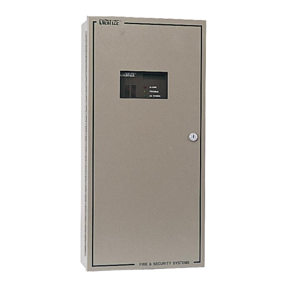
The inner door is hinged to allow easy removal. The enclosure is intended for indoor use only. An optional NEMA 3R enclosure is available. The RAD-32/64 is placed inside of the NEMA 3R enclosure. 1.4.5 DIMENSIONS Height 25.0 in. -
Page 12: Transmitter
1.0 Watts (max) FCC REQUIREMENTS The RAD-32/64 complies with the limits set for a Class B computing device as specified in Subpart J of Part 15 of the FCC Rules and Regulations. This unit also complies with Part 90 of the FCC Rules and Regulations. -
Page 13: Installation
The cabinet must be securely fastened to the mounting surface using the four mounting holes. For this, DIGITIZE, INC. 700178-0000 REV. H 10/21 Specifications Subject to Change Without Notice... -
Page 14: Wiring
RAD-32/64. Do not connect field wiring until the panel has been fully tested beforehand. Tag all wiring for later connection to the unit. Please refer to Section 3, System Initialization. -
Page 15: Wiring
32 ZONE EOL 2.5.1 GENERAL Each 32 Zone EOL may be switch selected for zone groups of 32. A RAD-32 is supplied with one 32 Zone EOL (expandable to two). A RAD-64 is supplied with two 32 Zone EOL boards. - Page 16 RAD-32/64 INSTALLATION AND USER MANUAL Figure 2.1 - RAD-32/64 Door Label DIGITIZE, INC. 700178-0000 REV. H 10/21 Specifications Subject to Change Without Notice...
-
Page 17: System Initialization
3 SYSTEM INITIALIZATION GENERAL For initial set-up of the RAD-32/64, complete the following instructions in the order in which they appear. However, if it is necessary to set the time on the internal clock during the operation of the unit, the time can be set without going through the power-up sequence. - Page 18 RAD-32/64 INSTALLATION AND USER MANUAL DIGITIZE, INC. 700178-0000 REV. H 10/21 Specifications Subject to Change Without Notice...
-
Page 19: Programming
4 PROGRAMMING PROGRAM INITIALIZATION Upon power-up, the RAD-32/64 panel will display the number of input boards installed. Verify that all of the input boards on the panel are on the display. Press the “CLEAR” button to continue. The time will appear on the display along with any alarm and fault conditions that the DGM finds during its initialization process. -
Page 20: Function 0 (Setting Box Number)
Set Zone Delays 4.3.1 FUNCTION 0 (SETTING BOX NUMBER) This function is used to set the “Box” number to be transmitted by the RAD-32/64 Radio Alarm Transmitter. The number must be entered in a six-digit format. Box numbers with less than six digits must be prefixed by zeros. -
Page 21: Function 2 (Numbers Or Rounds)
1=X”. Enter a number of digits, then press “ENTER”. Press “CLEAR” to exit. 4.3.3 FUNCTION 2 (NUMBERS OR ROUNDS) This function sets the number of rounds (transmissions) that the RAD-32/64 will emit when actuated. Only numbers one through three are valid entries. -
Page 22: Function 6 (Set "Test Box" Interval)
RAD-32/64 INSTALLATION AND USER MANUAL To change the time, press “5” then “ENTER”. The display will read “FUNC 5=XXXXXX”. Enter in the new time on the keypad and press “ENTER” Only valid times will be accepted. An incorrect entry will display the message “NOT VALID ENTRY.” To exit or abort press “CLEAR”. -
Page 23: Function 10 (Zone Input Settle Time)
4.3.13 FUNCTION 12 (BEEP CONTINUOUSLY WHILE IN ALARM) Enabling Function 12 will cause the RAD-32/64 to beep constantly when any of the zone inputs are in the Alarm mode. The beeper can only be cleared when the alarm condition has been removed. -
Page 24: Function 15 (Select Radio Format)
4.3.16 FUNCTION 15 (SELECT RADIO FORMAT) This function selects the radio format that the RAD-32/64 will transmit. The default for Function 15 is 0 (Eagle Signal). To view or change Function 15, press “15”, then “ENTER.” The display should now read “FUNC 15 =X”. -
Page 25: Function 18 (Send First Prefix)
RAD-32/64 INSTALLATION AND USER MANUAL 4.3.19 FUNCTION 18 (SEND FIRST PREFIX) Function 18 will cause the panel to send one prefix tone before transmitting the box number. Function 20 determines the prefix tone, which is actually sent. This option only affects the Eagle Signal and King Fisher formats. -
Page 26: Function 23 (Panel Trouble)
RAD-32/64 INSTALLATION AND USER MANUAL To view or change Function 22, press “22”, then “ENTER.” The display should now read “FUNC22=X”. Ent r a “0” to disable this function. Enter a “1” send a “LOW BATTERY” when the AC power fails 4.3.24 FUNCTION 23 (PANEL TROUBLE) -
Page 27: Function 41 (Tone Assignment, Panel Trouble)
“FUNC 41 = X” Enter the tone you wish to assign to that zone. Any value from zero to 15 is valid. Press, “CLEAR” TO EXIT. Function 41 is not used if you use the Digitize 99 Zone or King Fisher IRAC radio format. It only pertains to the Eagle Signal or King Fisher Radio Format. -
Page 28: Function 43 (Tone Assignment, Box Test)
“FUNC 43 = X” Enter the tone you wish to assign to that zone. Any value from zero to 15 is valid. Press “CLEAR” to exit. Function 43 is not used if you use the Digitize 99 Zone or King Fisher IRAC radio format. It only pertains to the Eagle Signal or King Fisher Radio Format. - Page 29 RAD-32/64 INSTALLATION AND USER MANUAL Function 1 (Number of Digits) 4 digits Function 2 (Number of Rounds) 3 rounds Function 3 (Pass number) 123456 Function 4 (Set Time) Does not change Function 5 (Set First Test Box Time) Does not change...
-
Page 30: Function 47 (Setting Zone Delays)
RAD-32/64 INSTALLATION AND USER MANUAL Function 36 (Tone Assignment, Zone 12) 11 (Tones 3, 9) Function 37 (Tone Assignment, Zone 13) 12 (Tones 4, 9) Function 38 (Tone Assignment, Zone 14) 13 (Tones 5, 9) Function 39 (Tone Assignment, Zone 15) -
Page 31: Theory Of Operation
5 THEORY OF OPERATION CONTROLS The following is a list of the various controls located on the front panel of the RAD-32/64. Numerical buttons are for entering information such as time, zone numbers, and function numbers. NOTE: If a button is pressed that is not used by the RAD-32, then “??????”will appear on the lower line of the display. -
Page 32: Beeper
DC POWER LED - This LED will be lit any time DC power is available to the IC’s. TRANSMITTER LED - This LED will be lit only when the RAD-32/64 is transmitting data. RESET LED - This LED will be lit when an internal malfunction occurs on the RAD. If the LED should illuminate, you must push the RESET button. -
Page 33: Standby Power Operation
RAD-32/64 INSTALLATION AND USER MANUAL 5.2.5 STANDBY POWER OPERATION The RAD-32/64 transfers the system power load to the standby battery whenever the main power fails or falls below the nominal level. The system will remain fully functional in this mode until the main power is restored or the system detects a low battery condition. - Page 34 RAD-32/64 INSTALLATION AND USER MANUAL DIGITIZE, INC. 700178-0000 REV. H 10/21 Specifications Subject to Change Without Notice...
-
Page 35: Testing
6 TESTING GENERAL Before connecting any field wiring, the RAD-32/64 should be powered up and tested completely. Test each control and indicator (refer to Section 5, Theory of Operation). All field wiring must be tested before proceeding to the next step. If the wiring has not been tested, refer to Section 2.3, Field Wiring for instructions. - Page 36 RAD-32/64 INSTALLATION AND USER MANUAL FUNCTION/ZONE ALARM TROUBLE FUNCTION/ZONE ALARM TROUBLE FUNCTION/ZONE ALARM TROUBLE FUNCTION/ZONE ALARM TROUBLE FUNCTION/ZONE ALARM TROUBLE FUNCTION/ZONE ALARM TROUBLE FUNCTION/ZONE ALARM TROUBLE FUNCTION/ZONE ALARM TROUBLE DIGITIZE, INC. 700178-0000 REV. H 10/21 Specifications Subject to Change Without Notice...
-
Page 37: Appendix Atone Frequencies
7 APPENDIX A TONE FREQUENCIES TONE FREQUENCIES TONE FREQUENCY (Hz) DIGITIZE, INC. 700178-0000 REV. H 10/21 Specifications Subject to Change Without Notice... - Page 38 RAD-32/64 INSTALLATION AND USER MANUAL DIGITIZE, INC. 700178-0000 REV. H 10/21 Specifications Subject to Change Without Notice...
- Page 39 EAGLE SIGNAL/KING FISHER RADIO FORMATS ZONE ASSIGNMENTS FOR TWO FUNCTION TONES ZONE FUNCTION FUNCTION TONE 1 TONE 2 ZONE ASSIGNMENT FOR ONE FUNCTION TONE ZONE FUNCTION TONE 1 DIGITIZE, INC. 700178-0000 REV. H 10/21 Specifications Subject to Change Without Notice...
- Page 40 RAD-32/64 INSTALLATION AND USER MANUAL DIGITIZE, INC. 700178-0000 REV. H 10/21 Specifications Subject to Change Without Notice...
- Page 41 Digitizes products by salesmen, dealers, distributors or agents, unless confirmed in writing by a Digitize officer. If the firmware or hardware is altered or modified by the Buyer, this firmware and hardware is not covered within this limited warranty and the Buyer bears sole responsibility and liability for that firmware and hardware.
Need help?
Do you have a question about the RAD-32 and is the answer not in the manual?
Questions and answers