
Related Manuals for Metasys SS12ADA Series

Summary of Contents for Metasys SS12ADA Series
-
Page 1: Table Of Contents
Fire Initiating Devices and Notification Appliances Technical Manual 408 Notification Appliances Section Technical Bulletin Issue Date 1095 SS12/24ADA Series Strobes and MASS12/24ADA Series Sounder/Strobes Introduction Page General Description Installation Procedures General Information Mounting Wiring Installation Guidelines Limitations © 1995 Johnson Controls, Inc. Code No. - Page 2 2 Notification Appliances—SS12/24ADA Series Strobes and MASS12/24ADA Series Sounder/Strobes...
-
Page 3: Mass12/24Ada Series Sounder/Strobes
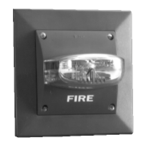
Introduction This document contains important information about installing and operating SS12/24ADA series strobes and MASS12/24ADA series sounder/strobes. These strobes and sounder/strobes are manufactured by System Sensor for use with Johnson Controls systems. The strobes are UL 1971 Listed for signaling devices for the hearing impaired. The strobes were tested by UL and those models that produce 75 candela (cd) meet the Americans with Disabilities Act (ADA) requirements of 75 cd of light output on axis. - Page 4 Note: The strobe cannot operate from coded power supplies, which produce interrupted power. The strobe must have an uninterrupted source of power in order to operate correctly. TO P 4 in. sq. 2-3/4 in. 1/4 in. 3 in . S S 12/24A D A Series TO P 1-11 /32 in.
- Page 5 Table 1: SS12/24ADA and MASS12/24ADA Series Specifications Mechanical Input Terminals 12 to 18 AWG (3.31 to 0.82 mm Dimensions 4 in. (101 mm) square SS12/24ADA MASS12/24ADA Front of backbox to front of unit 2-3/4 in. (70 mm) 3-3/4 in. (95.3 mm) Front of backbox to back of unit 1/4 in.
- Page 6 Light Distribution UL 1971 requires a polar light distribution pattern to enhance the likelihood of alerting hearing impaired individuals throughout an area. Figure 2 illustrates the way the standard measures light intensity, both horizontally and vertically. Wall Mount Vertical Light Distribution P erce n t of R ated Zero Axis...
- Page 7 Table 2: Sound Output and Current Ratings for the MA12/24D Sound (Hz) Clips on Current (mA) Output (dBA) Output (dBA) Tone Description Tabs in Anechoic in UL Chamber* Reverberant Room** Slow Whoop 800-1200 Hz Sweep in 5.0 sec/ Repeat 800 Hz Continuous 800/1000 Hz Alternating 800 Hz in 0.25 sec/1000 Hz in 0.25 sec/Repeat...
- Page 8 Selecting Desired For tab clip removal and storage (Figure 3): Tone Use a small bladed screwdriver to remove the clips. Slide the cover back to align the cover slot with the clip storage post to store unused clips. U se a sm a ll scre w d rive r to re m o ve clip s.
- Page 9 Table 3: Operating Current from Regulated Supply Model Number* Supply Average Peak Current Peak Current Inrush Voltage Operating (mA) (mA) Current Range Current 20/30 VDC 10.5/17 VDC (mA in (mA) Excess of Peak) SS24110ADA 20-30 VDC 470/500 – 20-30 VDC 385/400 –...
- Page 10 10 Notification Appliances—SS12/24ADA Series Strobes and MASS12/24ADA Series Sounder/Strobes...
-
Page 11: Installation Procedures
Installation Procedures This section contains installation information for SS12/24ADA series General strobes and MASS12/24ADA series sounder/strobes. Mounting Information instructions and wiring information are provided. Installation procedures must conform to all applicable codes and the requirements of the authority having jurisdiction. Strobe Placement For strobe placement, read and be familiar with: NFPA 72-National Fire Alarm Code, Chapter 6 (1993) - Page 12 Sounder For mounting the sounder, note the following figures: Mounting Surface Mount (Figure 4) Semi-flush Mount (Figures 7 and 10) Flush Mount (Figure 9) Flush mounting requires the use of the deep backbox (Part No. BB-D) or 4 inches square by 2-3/4 inches deep backbox. 1.
- Page 13 S tandard 4 in ch S qu are x 2 -1 /8 inch B ackbox su rm o u nt M A-12 /2 4 D Figure 4: Sounder Surface Mount 1. Complete the field wiring as described in the Wiring Installation Guidelines section of this technical bulletin (Figure 11).
- Page 14 S tandard 4 inch Sq uare x 2-1/8 inch B ackbox s u rm on 2 a S ignal S trobe/S ou nder Figure 6: Sounder/Strobe Surface Mount 1. Complete the field wiring as described in the Wiring Installation Guidelines section of this technical bulletin (Figures 12 and 14). Screw the sounder/strobe to the box with Type A screws.
- Page 15 S tandard 4 inch S quare x 2-1/8 inch B ackbox surm o nt1 M P -S F S ig na l S trob e/S ou nd e r Figure 7: Sounder or Sounder/Strobe Semi-Flush Mount 1. Add Type D nuts to the plate. Screw the plate to the box with Type E screws.
- Page 16 S tandard 4 inch S quare x 2-1/8 inch B ackbox s u rm on 1 1 M P-S F S ignal Strobe Figure 8: Strobe Semi-Flush Mount 1. Add Type D nuts to the plate. 2. Screw the strobe to the plate with Type C screws. 3.
- Page 17 B B -D 4 inch S qu ar e x 2-3/4 inch D eep B ackbox surmon12 M A -1 2/2 4D M PF2 Figure 9: Sounder Flush Mount (Deep Box Required) 1. Add Type D nuts to the plate. 2.
- Page 18 S tan dard 4 inch S quare x 2-1/8 inch B ackbox s u rm o n t9 P laster R ing M P -S F S ignal S trobe/S ounder Figure 10: Sounder or Sounder/Strobe Semi-Flush Mount with Plaster Ring 1.
-
Page 19: Wiring Installation Guidelines
Note: Do not loop the Notification Appliance Circuit (NAC) wires under Wiring the terminal screw. Wires connecting the device to the panel must Installation be broken at the device terminal connection in order to maintain Guidelines electrical supervision. Wiring Diagrams T o N ext V D C Dev ice... - Page 20 C eiling U p From U n cod ed D C P ower S up ply..O ut T o N ext D evic e From U n cod ed D C P ower S up ply..O ut T o N ext D evic e high in 12 Floor D own Figure 13: Wiring the Strobe...
-
Page 21: Limitations
These strobes and sounder/strobes are designed for installation in Limitations accordance with NFPA-Standards-72-National Fire Alarm Code or equivalent codes and standards applicable to the country of installation. Test your alarm system per the applicable codes and standards specific to the location and use of your facility. The sounder and/or strobe will not work without power. - Page 22 Notes 22 Notification Appliances—SS12/24ADA Series Strobes and MASS12/24ADA Series Sounder/Strobes...
- Page 23 Notes Notification Appliances—SS12/24ADA Series Strobes and MASS12/24ADA Series Sounder/Strobes 23...
- Page 24 Notes Controls Group FAN 408 507 E. Michigan Street Fire Initiating Devices and Notification Appliances Technical Manual P.O. Box 423 Printed in U.S.A. Milwaukee, WI 53201 24 Notification Appliances—SS12/24ADA Series Strobes and MASS12/24ADA Series Sounder/Strobes...
Need help?
Do you have a question about the SS12ADA Series and is the answer not in the manual?
Questions and answers