
Summary of Contents for Matsushita Electric NAiS FP Series
- Page 1 PROGRAMMABLE CONTROLLER FP0 S–LINK Unit Hardware Manual is a global brand name of Matsushita Electric Works.
- Page 3 BEFORE BEGINNING This manual and everything described in it are copyrighted. You may not copy this manual, in whole or part, without written consent of Matsushita Electric Works, Ltd. Matsushita Electric Works, Ltd. pursues a policy of continuous improvement of the design and performance of its products, therefore, we reserve the right to change the manual/product without notice.
- Page 5 Introduction Thank you for purchasing the FP0 S–LINK control unit. The FP0 S–LINK control unit is designed exclusively for the FP0 programmable controller, and is equipped with numerous functions that make it easy to use the S–LINK with the FP0. This hardware manual describes the functions, installation, wiring, and operation of the FP0 S–LINK control unit.
- Page 7 Important Symbols The following symbols are used in this manual: Note Contains important additional information or indicates that you should proceed with caution. Example: Contains an illustrative example of the previous text section. * next page Indicates that the text will be continued on the next page.
- Page 9 Table of Contents Chapter 1 Features and Restrictions Features ............1 –...
- Page 10 Table of Contents FP0 S–LINK Unit Chapter 5 Operation Sequence of Turning on Power Supplies ......5 –...
-
Page 11: Table Of Contents
Chapter 1 Features and Restrictions Features ........1 –... - Page 12 Features and Restrictions FP0 S–LINK Unit 1 – 2 Matsushita Automation Controls...
-
Page 13: Features
FP0 S–LINK Unit Features and Restrictions Features Features By having fewer wiring and construction functions, the S–LINK with a T–branch enables a more compact control panel, with no modifications required. Control of S–LINK input/output devices with 64 inputs and 64 outputs is supported. Additionally, expansion units can be added to accommodate up to three units, enabling efficient I/O wiring. -
Page 14: Restrictions
Features and Restrictions FP0 S–LINK Unit Restrictions Restrictions 1.2.1 Unit Combinations First FP0 S–LINK Second Third expansion unit control unit expansion unit expansion unit Maximum possible expansion is with a total of 3 units A maximum of three expansion I/O units can be connected to one FP0 S–LINK control unit. -
Page 15: Current Consumption
FP0 S–LINK Unit Features and Restrictions Restrictions 1.2.3 Current Consumption The internal current consumption (5V power supply) for the FP0 S–LINK control unit is as shown below. When configuring the system, the usage conditions of other units should be taken into consideration and included in the capacity of the power supply unit. Name Model no. - Page 16 Features and Restrictions FP0 S–LINK Unit Restrictions 1 – 6 Matsushita Automation Controls...
- Page 17 Chapter 2 Parts and Specifications Names and Functions ......2 – 3 Specifications ........2 –...
- Page 18 Parts and Specifications FP0 S–LINK Unit 2 – 2 Matsushita Automation Controls...
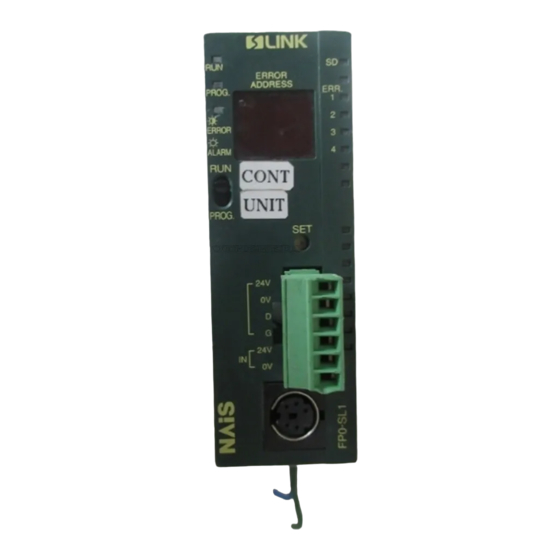
- Page 19 FP0 S–LINK Unit Parts and Specifications Names and Functions Names and Functions à À Ä Á Â Å Æ Ç É È Status indicator LED The LED display the operation mode and error statuses. ERROR ADDRESS display (2–digit hexadecimal display) The address at which the S–LINK system error occurred is displayed.
- Page 20 Parts and Specifications FP0 S–LINK Unit Names and Functions S–LINK terminal block (6–pin) The power supply and signal wires of the S–LINK system are connected to the S–LINK terminal block. The S–LINK terminal block can be detached from the FP0 S–LINK control unit for wiring operations.
- Page 21 FP0 S–LINK Unit Parts and Specifications Specifications Specifications 2.2.1 General Specifications Item Description Rated operating voltage 24V DC Operating voltage range 21.6V to 26.4V DC Rated current consumption 150mA or less Allowed momentary power off time 10ms at 21.6V, 10ms at 24V Ambient temperature 0°C to +55°C/32°F to +131°F Storage temperature...
- Page 22 Parts and Specifications FP0 S–LINK Unit Specifications 2.2.2 Performance Specifications Item Description Programming method/Control method Relay symbol/Cyclic operation Controllable I/O points Control unit only S–LINK section: max. 128 Input: 64 Output: 64 With expansion Expansion section: max. 96 Program memory Built in EEPROM (no back-up battery required) Program capacity 5,000 steps...
- Page 23 FP0 S–LINK Unit Parts and Specifications Specifications Item Description Memory Timer Non-hold type: all points backup Counter Non-hold type From set value to C127 (* note 1) Hold type 16 points (elapsed values) C128 to C143 Internal Non-hold type 880 points (R0 to R54F) relay 55 words (WR0 to WR54) Hold type...
- Page 24 Parts and Specifications FP0 S–LINK Unit Specifications 2.2.3 S–LINK Controller Specifications Item Description 24V DC "10% / Allowable ripple p – p " 10% max. " " Rated power supply voltage (Supplied from IN – 24V, IN – 0V of the S–LINK terminal block) Current consumption Current consumption [S–LINK controller current consumption (including D –...
- Page 25 Chapter 3 I/O Allocation How to Count the I/O Numbers ....3 – 3 I/O Numbers of S–LINK Control Unit ....3 –...
- Page 26 I/O Allocation FP0 S–LINK Unit 3 – 2 Matsushita Automation Controls...
- Page 27 FP0 S–LINK Unit I/O Allocation How to Count the I/O Numbers How to Count the I/O Numbers Specifying X and Y numbers On the FP0, the same numbers are used for input and output. Example: The same number “X80 and Y80” can be used for input and output Expression of numbers for input/output relays Since input relay (X) and output relay (Y) are handled in units of 16 points, they are expressed as a combination of decimal and hexadecimal numbers as shown below.
- Page 28 I/O Allocation FP0 S–LINK Unit I/O Numbers of S–LINK Control Unit I/O Numbers of S–LINK Control Unit The I/O allocation of the FP0 S–LINK control unit is fixed. Unit FP0 I/O S–LINK address Input (64 points) X80 to X8F 0 to 15 X90 to X9F 16 to 31 X100 to X10F...
- Page 29 Chapter 4 Wiring Wiring the Power Supply ......4 – 3 4.1.1 Wiring to Power Supply Connector .
- Page 30 Wiring FP0 S–LINK Unit 4 – 2 Matsushita Automation Controls...
- Page 31 FP0 S–LINK Unit Wiring Wiring the Power Supply Wiring the Power Supply With the FP0 S–LINK control unit, power must be supplied at two locations (power supply connector and S–LINK terminal block). 4.1.1 Wiring to Power Supply Connector This is the power supply for the programmable controller section and the S–LINK controller in the S–LINK control unit (24V DC, 150mA).
- Page 32 Wiring FP0 S–LINK Unit Wiring the Power Supply S–LINK terminal block: MC1.5/6–ST–3.5 (Made by Phoenix Contact Co.) Terminal name Color of connecting Description cable Brown Main wire (for S–LINK I/O devices) Blue White Black IN–24V — External power supply input for S–LINK IN–0V —...
- Page 33 Chapter 5 Operation Sequence of Turning on Power Supplies ... 5 – 3 Operation When Power Supply is Turned On ..5 – 4 S–LINK System Address Recognition .
- Page 34 Operation FP0 S–LINK Unit 5 – 2 Matsushita Automation Controls...
-
Page 35: Sequence Of Turning On Power Supplies
FP0 S–LINK Unit Operation 5.1 Sequence of Turning on Power Supplies Sequence of Turning on Power Supplies When turning on the power supplies to the S–LINK control unit, follow the sequence outlined below. Procedure: Turn on the power supply to the S–LINK I/O devices connected to the S–LINK system. -
Page 36: Operation When Power Supply Is Turned On
Operation FP0 S–LINK Unit Operation When Power Supply is Turned On Operation When Power Supply is Turned On Refreshing S–LINK I/O data With the S–LINK control unit, I/O data is refreshed by the CPUs of both the FP0 section and the S–LINK section, through the memory shared between them. S–LINK control unit I/O data area... -
Page 37: S-Link System Address Recognition
FP0 S–LINK Unit Operation S–LINK System Address Recognition S–LINK System Address Recognition 5.3.1 Recognizing the Address Before the S–LINK system is being operated for the first time, turn on the power supply and then press the system SET button. When the system SET button is pressed, the number of connected devices recognized by S–LINK control unit blinks on the error address display in hexadecimal. -
Page 38: Address Setting Of S-Link I/O Device
Operation FP0 S–LINK Unit S–LINK System Address Recognition 5.3.2 Address Setting of S–LINK I/O Device Addresses can be set freely, regardless of the position of the I/O device connected to the system, but problems in the wiring of the main cable, such as broken or disconnected wires, can be detected more easily if I/O devices closer to the S–LINK control unit are given smaller addresses, and addresses increase in sequential order for I/O devices which are farther away from the S–LINK control unit. - Page 39 Chapter 6 What to Do If an Error Occurs Judging Errors from the Error Indicators ... . 6 – 3 Judging Errors Address Displays ....6 –...
- Page 40 What to Do If an Error Occurs FP0 S–LINK Unit 6 – 2 Matsushita Automation Controls...
- Page 41 FP0 S–LINK Unit What to Do If an Error Occurs Judging Errors from the Error Indicators Judging Errors from the Error Indicators If an error occurs in the S–LINK system, the ERROR indicator indicated in the table below lights, depending on the content of the error. Description Steps to take ERROR indicators...
- Page 42 What to Do If an Error Occurs FP0 S–LINK Unit Judging Error Address Displays Judging Error Address Displays The transmission line is monitored at all times, and if an error occurs, the address at which the error occurred is displayed as a hexadecimal value. ERROR indicator ERROR ADDRESS...
- Page 43 Chapter 7 Dimensions FP0 S–LINK Control Unit ......7 – 3 Mounting on DIN Rail ......7 –...
- Page 44 Dimensions FP0 S–LINK Unit 7 – 2 Matsushita Automation Controls...
- Page 45 FP0 S–LINK Unit Dimensions FP0 S–LINK Control Unit FP0 S–LINK Control Unit Reference measuring for wiring. External dimensions (unit: mm/in.) 10/0.394 30.0/ 60.0/2.362 1.181 ERROR EXPANSION ADDRESS PROG CONNECTOR ERROR ALARM PROG. 90.0/3.543 7.5/0.295 9/0.354 17/0.669 DIN standard rail (DIN EN50022 35/1.378 width) Matsushita Automation Controls 7 –...
- Page 46 Dimensions FP0 S–LINK Unit Mounting on DIN Rail Mounting on DIN Rail Top view (unit: mm/in.) 67.5/2.657 60.0/2.362 Front view (unit: mm/in.) 45/1.772 90.0/3.543 45/1.772 A+B+C+D dimensions (unit: mm/in.) Control unit type A+B+C A+B+C+D (Control unit (1 expansion unit (2 expansion (3 expansion only) connected)
- Page 47 Index Address recognition, 5 – 5 Pin assignment, 2 – 4 Power supply, Sequence, 5 – 3 Power supply connector, 2 – 4 Current consumption, 1 – 5 Refreshing, 5 – 4 RS232C port, 2 – 4 DIN Rail, Mounting, 7 – 4 S–LINK, T–branch, 1 –...
- Page 48 Index FP0 S–LINK Unit I – 2 Matsushita Automation Controls...
- Page 49 Record of Changes Manual No. Date Description of Changes ARCT1F263END January 2000 First edition...
- Page 51 Rudolf–Diesel–Ring 2, 83607 Holzkirchen, Germany, Tel. (08024) 648–0, Fax (08024) 648–555, http://www.matsushita.de H Ireland Matsushita Electric Works Ltd., Irish Branch Office Waverley, Old Naas Road, Bluebell, Dublin 12, Republic of Ireland, Tel. (01) 460 09 69, Fax (01) 460 11 31 H Italy Matsushita Electric Works Italia s.r.l.
Need help?
Do you have a question about the NAiS FP Series and is the answer not in the manual?
Questions and answers