Table of Contents
Advertisement
Advertisement
Table of Contents

Summary of Contents for Pall iCELLis 500+
- Page 1 1.1.1.1 Instructions for Use Part A: Hardware USD3310 ® iCELLis 500+ Bioreactor Control System Part Number: ICL500CSSSIP Instructions For Use Part A: Hardware USD 3310 ® iCELLis 500+ control system Part Number: ICL500CSSSIP Filtration. Separation. Solution.
-
Page 2: Table Of Contents
Table of Contents Introduction ________________________________________________________ 4 Warnings __________________________________________________________ 5 Hazard Icons ______________________________________________________________ 5 Hazard Level ______________________________________________________________ 6 Safety Messages ___________________________________________________________ 7 Overview _________________________________________________________ 10 iCELLis 500+ Single-Use Fixed-Bed Bioreactor ___________________________________ 10 iCELLis 500+ Control System _________________________________________________ 11 iCELLis 500+ Control System Environment Requirements ________________ 15 Unpacking and Installing the iCELLis 500+ Control System _______________ 16 Unpacking ________________________________________________________________ 16 Moving and Positioning the iCELLis 500+ Control System __________________________ 18... - Page 3 Disposal __________________________________________________________ 45 Technical Assistance _______________________________________________ 46 Appendix A: Abbreviations and Symbols _____________________________________ 47 Page 3 of 48...
-
Page 4: Introduction
1. Introduction All information presented in this document has been verified according to applicable standards and guidelines at the time of writing. All legal and other binding regulations for personnel protection, accident prevention and protection of the environment applicable in the country of use of the system must be observed. -
Page 5: Warnings
2. Warnings 2.1 Hazard Icons The following icons are used in this Instruction for Use to point out hazards resulting from the utilization of the system described. Documentation must be carefully assessed where these icons are present. General icon for DANGER, WARNING, CAUTION or ALERT This symbol notifies general risk or specific procedures, which if not followed correctly, can result in injury of personnel or damage to equipment. -
Page 6: Hazard Level
CAUTION Tip over hazard Risk of tipping of the accessories pump. Do not lean on the pump head of the accessories pumps. CAUTION Surface may be hot inside. Risk of burn. Allow to cool before opening the bag pre-heater. CAUTION Strong magnetic field. Interaction with metallic objects may produce Pinch Hazards. -
Page 7: Safety Messages
Before using the iCELLis 500+ control system, ensure you read and understand the safety instructions to prevent any damage to the equipment or any physical injury. Pall shall not be held responsible for any damage that may result from misuse. Misuse includes any use other than that designed for the iCELLis 500+ bioreactor and control system. - Page 8 during operation. DANGER! Oxygen causes a fire/explosion risk! Users are responsible for performing their own safety assessment and obtaining expert advice on the design of any system used to supply gases to the iCELLis 500+ control system. RELEVANT ONLY WHEN USING OXYGEN: In the unlikely event of a tubing or connection failure, oxygen may build up in and around the iCELLis 500+ control system.
- Page 9 500+ control system is powered. ALERT! Risk of damage to equipment! Only exhaust filter heater provided by Pall should be used with the iCELLis 500+ control system. ALERT! Risk of damage to equipment! The iCELLis 500+ control system should never be moved when there is liquid in the bioreactor.
-
Page 10: Overview
The iCELLis 500+ bioreactor is fully sinle-use including its sensors. The bioreactor vessel contains a pre-packed fixed-bed made of Pall’s proprietary iPack carriers designed for both suspension and adherent cells which grow entrapped in the fixed-bed. This matrix is made of medical grade polyethylene teraphalate (PET). -
Page 11: Icellis 500+ Control System
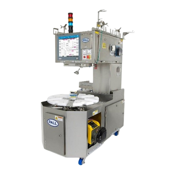
Figure 1: iCELLis 500+ bioreactor 3.2 iCELLis 500+ Control System The iCELLis 500+control system was specifically designed to operate, monitor and control the iCELLis 500+ bioreactors. The system body is composed of grade 304/316 L stainless steel and houses the following elements (Figure 2): •... - Page 12 Top assembly Touch screen panel Middle assembly Docking station Bottom assembly Optional High Flow peristaltic pumps Figure 2: iCELLis 500+ control system An overview of the iCELLis 500+ control system components in front, rear, right and left views are presented in Figure 3, Figure 4 and Figure 5. Page 12 of 48...
- Page 13 Figure 3: iCELLis 500+ control system front view Figure 4: iCELLis 500+ control system rear view Page 13 of 48...
- Page 14 Figure 5: iCELLis 500+ control system right and left views Page 14 of 48...
-
Page 15: Icellis 500+ Control System Environment Requirements
4. iCELLis 500+ Control System Environment Requirements WARNING! Risk of injury to personnel and/or damage to equipment! The iCELLis 500+ control system is not ATEX certified. The system may not be operated in potentially explosive atmosphere. DANGER! Risk of injury to personnel and/or damage to equipment! Before installing the iCELLis 500+ control system, verify that the floor can support the weight of the system, the ancillary equipment and their content (such as cell culture media). -
Page 16: Unpacking And Installing The Icellis 500+ Control System
5. Unpacking and Installing the iCELLis 500+ Control System The required materials for unpacking and installing the iCELLis 500+ control system are detailed below: • Forklift with minimum fork length of 1.4 m capable of lifting 1.320 kg at the full length of the forks. - Page 17 Figure 6: Uncrating the iCELLis 500+ control system – a) Crated unit, b) Removing crate fixing clips, c) Lifting side panel, d) Removing side panel, e) Side panel removed, f) Unit with double plastic wrap, g) Unit with external wrap removed, h) Unit unwrapped and lifting points (blue), i) Crate for accessories and documentation. Page 17 of 48...
-
Page 18: Moving And Positioning The Icellis 500+ Control System
5.2 Moving and Positioning the iCELLis 500+ Control System WARNING! Risk of injury to personnel and/or damage to equipment! Manipulation and repositioning of iCELLis 500+ control system must be completed when the iCELLis 500+ bioreactor is completely empty and must be done by two or more persons due to the weight of the bioreactor. -
Page 19: Locking In Position And Levelling The System
Figure 7: Load cell locking plate removal at system reception: a) Load cell with locking plate in place, b) Locking plate and fixation elements, c) Locking plate and bolts removed, d) Checking sleeve and anti-lift bolt in place. Locking in Position and Levelling the System Once the iCELLis 500+ control system is in its required position the wheels should be turned and feet lowered to lock the casters (Figure 8). -
Page 20: Fitting High Speed Pumps On The Icellis 500+ Control System
5.3 Fitting High Speed Pumps on the iCELLis 500+ Control System WARNING! Risk of injury to personnel and/or damage to equipment! The positioning of the high-speed pumps must be done by two people due to the weight of the pumps. ALERT! Risk of damage to equipment! Always check the position and stability of the accessories pump before operation. -
Page 21: Fitting The Base Scale On The Icellis 500+ Control Aystem
5.4 Fitting the Base Scale on the iCELLis 500+ Control System The Base scale is packed in the crate for accessories and documentation. Unpack the Base scale and follow the procedure below to install and connect it to the iCELLis 500+ control system. Install the Base scale on the iCELLis 500+ control system as per Figure 10a-b. -
Page 22: Fitting The Tubing Holders On The Icellis 500+ Control System
5.5 Fitting the Tubing Holders on the iCELLis 500+ Control System The tubing holders are packed in the crate for accessories and documentation. The content of tubing holder pack is described in Table 4 below. Table 4: Tubing holders pack items and description (The item number is used in Figure 11) Item number Description Quantity... -
Page 23: Fitting Communication And Sensor Cables To The Icellis 500+ Control System
5.6 Fitting Communication and Sensor Cables to the iCELLis 500+ Control System ALERT! Risk of damage to equipment! All cables should be hand-tightened (no tools). Connecting the Double Jacket Pressure Sensor Cable: The double jacket pressure sensor cable is packed in the crate of the accessories and documentation. Figure 12: Double jacket pressure sensor cable Connect the cable to the connector labeled ‘DJ PRESSURE SENSOR’... - Page 24 Figure 14: Bioreactor pressure sensor cable Connect the cable to the connector labeled ‘BIOREACTOR PRESSURE SENSOR’ located on the front of the iCELLis 500+ control system (Figure 15a). Secure the connector by turning the metallic part of the connector (Figure 15b). Figure 15.
-
Page 25: Connecting The T1 And T2 Temperature Probes
Connecting the T1 and T2 Temperature Probes: The T1 (grey cable) and T2 (white cable) temperature probes are packed in the crate of the accessories and documentation. Figure 16: T1 (grey cable) and T2 (white cable) temperature probe Connect the T1 temperature probe cable to the connector labeled ‘T1’ located on the front of the iCELLis 500+ control system (Figure 17a). -
Page 26: Connecting Optical Fibers For Ph And Do
Figure 17: T1 and T2 temperature probes connection – a) Connect T1 temperature probe, b) Secured T1 connection, c) Connect T2 temperature probe, d) Secured T2 connection. Connecting Optical Fibers for pH and DO: ALERT! Risk of damage to equipment! Take care not to bend the optical fibers. - Page 27 Figure 19: Connection of optical fibers before and after fixed-bed – a) Optical connectors, b) Connection to the DO2 connector, c) Secured connection, d) Connection to the pH2 connector, e) All optical fibers connected. Page 27 of 48...
-
Page 28: Connecting The Filter Heater
Connecting the Filter Heater: The filter heater is packed in the crate of the accessories and documentation. Figure 20: Filter heater Connect the power connector of the filter heater to the connector labeled ‘POWER’ on the right side of the iCELLis 500+ control system (Figure 21a and b). Secure the connector by turning the metallic part of the connector (Figure 21c). - Page 29 Figure 21: Connectors of the filter heater – a & b) Connection of the power connector, c) Secured power connection, d) Connection of the temperature sensor, e) Secured connection of the temperature sensor. Page 29 of 48...
-
Page 30: Connecting The Bag Pre-Heater
Connecting the Media Bag Pre-Heater The media bag pre-heater (Figure 22) is packed in the crate of the accessories and documentation. Figure 22: Bag Pre-Heater First hook the upper back part of the media bag pre-heater into the support on the left side of the iCELLis 500+ control system (Figure 23a). -
Page 31: Installation Of The Temperature Control Unit (Tcu)
Connect the cable with label ‘C150/8’ to the connector labeled ‘C150/8’ located on the left of the bag pre-heater (Figure 24b). Secure the connector by turning the metallic part of the connector clockwise. Connect the cable with label ‘C26/3’ to the connector labeled ‘C26/3’ located to the left of the bag pre-heater (Figure 24c). - Page 32 WARNING! Bended tubing! Risk of injury to personnel and/or damage to equipment! Avoid sharp bends in the fluid tubing of the TCU, and maintain a sufficient distance from surrounding walls. Make sure that the tubing is securely attached. CAUTION! Risk of injury to personnel and/or damage to equipment! When the temperature control is active or when the system is cooling down, the TCU media pre-heater and filter heater may become extremely hot.
- Page 33 Figure 25: Connection of PROFIBUS cable between TCU and iCELLis 500+ control system – a) Front of TCU, including Interface panel, b) Side of TCU with Interface panel, c) Connections at the rear of iCELLis 500+ control system. Follow Figure 26 to assemble and install the TCU. Remove the TCU unit from the crate and install it on a flat surface (Figure 26a-b).
- Page 34 Figure 26: TCU installation procedure – a) TCU out of the box, b) Command touch panel, c) Connection of touch panel cable, d) TCU with Command touch panel, e) Connection of Profibus connector on TCU, f) Other end of Profibus cable on iCELLis 500+ bioreactor, g) TCU rear side image, h) Power cable, i) Connecting power on rear side of TCU, j) Barbed connectors for IN/OUT line on back of TCU and closure nuts, k) Removing existing closed nuts, l,m,n,o) fixing the connectors with nuts on IN/OUT lines.
-
Page 35: Icellis 500+ Control System Electrical Installation
*On a 3 phase 120 Vac network, 208 Vac can be obtained by using the voltage between 2 phases. Power Connection and Powering ON PALL recommends turning OFF the iCELLis 500+ control system after each batch, or whenever the system is not in use for a long period of time, to ensure the correct functioning of the equipment. -
Page 36: Fitting The Gas Supplies To The Icellis 500+ Control System
Turn the main power switch to ON to power the control system (Figure 27e-f). Figure 27: iCELLis 500+ control system powering – a) iCELLis 500+ main power socket and switch, b) Unscrewing protective cap, c) Removing protective cap, d) Plugging power cable, e) Locking power cable, f) Switching ON the control system. 5.9 Fitting the Gas Supplies to the iCELLis 500+ Control System DANGER! Oxygen causes a fire/explosion risk! Users are responsible for performing their own safety assessment and obtaining expert advice on the... - Page 37 Use of 0.2 to 0.45 µm filters between the gas delivery end-point and the iCELLis 500+ control system inlets is highly recommended to prevent mass flow controllers’ damage by dust particles. Contact your Pall representative for appropriate references. Page 37 of 48...
-
Page 38: Icellis 500+ Control System Specifications
6. iCELLis 500+ Control System Specifications 6.1 General Specifications Compliance with International Standards and Guidelines Electromagnetic The hardware has met the specification of EN 61326-1: 2013 and FCC Compatibility (EMC) CFR 47 Part 15, Sections 15.107 and 15.109 (Class A) Safety requirements for The hardware has met the specification of IEC 61010-1:2010 (third edition), electrical equipment for... - Page 39 Gas connections Air, carbon dioxide, oxygen and nitrogen are connected to the iCELLis 500+ control system using Swagelock ¼ in. tube OD (female connector on the iCELLis 500+ control system). All gases must be supplied dry and oil free and they must be regulated to a maximum of 2.5 barg (36.3 psig).
- Page 40 Double jacket over-pressure Interlock using disposable pressure sensor for measurement of the double protection jacket internal pressure Emergency stop 2 emergency stop buttons, 1 on the front and 1 on the left side of the iCELLis 500+ control system Top Assembly. Power failure data protection Integrated UPS for the safe shut down of the computer only.
-
Page 41: Sensors And Actuators Specifications
The greater the distance from the point of calibration, the lower the probability that the accuracy will be within specification. Therefore, if these bioreactors demonstrate a greater distance, then Pall’s recommendation is that the bioreactors can only be used under mitigation actions, specifically manual pH control. Our dedicated Application team can give you support for these mitigation actions. -
Page 42: Temperature Control Unit Specifications
+/- 1.0% of liquid weight (agitation from 0 - 300 rpm) WT_02 Weight bioreactor 0 ... 180,0 +/- 3.0% of liquid weight (agitation from 300-450 rpm) Speed feed-in pump ST_01 0 ... 360 +/- 2.0 (Watson Marlow 520R pump head) Speed base pump ST_02 0 ... -
Page 43: Cleaning
7. Cleaning WARNING! Risk of injury to personnel and/or damage to equipment! Never spray liquid or allow any ingress of fluid of any sort into the hardware cooling fan ports on the back and bottom of the iCELLis 500+ control system. WARNING! Risk of damage to equipment! Always switch off power to iCELLis 500+ control system, and then disconnect the mains/power cable before cleaning the hardware. -
Page 44: Maintenance
If any problems occur with the hardware, no attempt should be made to perform any maintenance on it as it may void any warranties. Please contact Pall (See Section 10). In any correspondence with Pall, the model, manufacturing part and serial numbers of the hardware should be recorded for reference. - Page 45 To document this, they have been marked with the following symbol: Please visit our website for more information and local instructions on disposing of the product at https://www.pall.com/en/about-pall/corporate-sustainability/weee-compliance.html. Page 45 of 48...
- Page 46 Technical Assistance For technical assistance, please contact: • Your local Pall representative • Visit www.pall.com • E-mail your enquiry to bioreactors@pall.com Or contact Pall: Corporate Headquarters European Headquarters Asia-Pacific Headquarters 25 Harbor Park Drive Avenue de Tivoli 3, 1 Science Park Road, #05-09/15...
- Page 47 Appendix A: Abbreviations and Symbols Abbreviation, Symbol Signification Ampere Barg, mbarg Bar, millibar, gauge pressure Declaration of European conformity Dissolved Oxygen Good Manufacturing Practice Human Machine Interface Hertz Isopropyl Alcohol m, mm Meter, millimeter Mass Flow Controller Outer Diameter P&ID Piping and Instrumentation Diagram Polyethylene terephthalate PETG...
- Page 48 +1 516 484 5400 phone Sweden, Switzerland, Taiwan, Thailand, the United Kingdom, the United States, and biopharm@pall.com e-mail Venezuela. Distributors in all major industrial areas of the world. To locate the Pall office or distributor nearest you, visit www.pall.com/contact. European Headquarters...
Need help?
Do you have a question about the iCELLis 500+ and is the answer not in the manual?
Questions and answers