Table of Contents
Advertisement
Quick Links
Distributed by: ABQ Industrial LP USA
Tel: +1 (281) 516-9292 / (888) 275-5772 eFax: +1 (866) 234-0451
Web: https://www.abqindustrial.net E-mail: info@abqindustrial.net
SMART FORCE AND TORQUE SENSORS
User's Guide
Distributed by: ABQ Industrial LP USA
Tel: +1 (281) 516-9292 / (888) 275-5772 eFax: +1 (866) 234-0451
Web: https://www.abqindustrial.net E-mail: info@abqindustrial.net
Advertisement
Table of Contents

Summary of Contents for ABQINDUSTRIAL Plug&Test MR01-50
- Page 1 Distributed by: ABQ Industrial LP USA Tel: +1 (281) 516-9292 / (888) 275-5772 eFax: +1 (866) 234-0451 Web: https://www.abqindustrial.net E-mail: info@abqindustrial.net SMART FORCE AND TORQUE SENSORS User’s Guide Distributed by: ABQ Industrial LP USA Tel: +1 (281) 516-9292 / (888) 275-5772 eFax: +1 (866) 234-0451...
-
Page 2: Table Of Contents
Thank you… Thank you for purchasing a Mark-10 Plug & Test remote sensor, designed for use with Mark-10 models ® M7I, M5I and M3I force/torque indicators and Series F test frames. With proper usage, we are confident that you will get many years of great service with this product. Mark- 10 sensors are ruggedly built for many years of service in laboratory and industrial environments. -
Page 3: Overview
1 OVERVIEW 1.1 General Overview Plug & Test sensors accommodate numerous force and torque measurement requirements, from 0.25 to ® 10,000 lbF (1 N to 50 kN) of force, and from 10 ozFin to 5,000 lbFin (7 Ncm to 550 Nm) of torque. These sensors can be handheld or mounted to a fixture or test stand for more sophisticated testing requirements. -
Page 4: Safety / Proper Usage
2 SAFETY / PROPER USAGE Read through the following safety instructions thoroughly before using a sensor: 1. Note the sensor’s capacity before use and ensure that the capacity is not exceeded. Producing a load greater than the indicated safe overload value can damage the sensor. An overload can occur whether the sensor’s indicator is powered on or off. -
Page 5: Setup
3 SETUP The Plug & Test connector must be inserted into the receptacle of the indicator with the side marked ® “Plug & Test Technology” facing up (see Fig. 3.1). When fully inserted, the connector will lock into place ® with a “click”. -
Page 6: Series R01 / R07 Force Sensors
4 SERIES R01 / R07 FORCE SENSORS 4.1 Unpacking and Assembly Carefully remove the sensor from the box. No assembly is required. 4.2 Installing Series R07 to Models F755 / F755S / F1505 / F1505S Test Frames Install the sensor to the underside of the crosshead using the supplied socket head screw and hardware. - Page 7 4.5 Dimensions (in [mm]) Series R07 force sensors are identical to Series R01, except for two thumb screws in the Plug & Test ® connector. These thumb screws are required for mounting to certain Series F test frames. Model No. MR01-50 / MR07-50 MR01-100 / MR07-100 0.46 [11.7]...
-
Page 8: Series R02 Force Sensors
5 SERIES R02 FORCE SENSORS 5.1 Unpacking and Assembly Carefully remove the sensor from the box. No assembly is required. 5.2 Overview Compression force may be applied to the button in the center of the top surface of the sensor (visible in the picture above). DO NOT apply load to the cover on the underside of the sensor. - Page 9 5.5 Capacity x Resolution With Model M7I / M5I Indicator With Model M3I Indicator Model MR02-100 100 x 0.05 1600 x 1 50000 x 20 50 x 0.02 500 x 0.2 100 x 0.1 50 x 0.05 500 x 0.5 MR02-200 200 x 0.1 3200 x 2...
-
Page 10: Series R03 Force Sensors
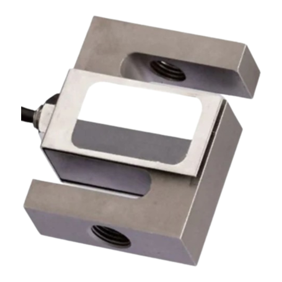
6 SERIES R03 FORCE SENSORS 6.1 Unpacking and Assembly Carefully remove the sensor from the box. Extra care should be taken for very low capacity models. No assembly is required. 6.2 Overview Tension and compression force may be applied to the threaded holes in the load cell shaft and opposite flat surface. -
Page 11: Series R04 Force Sensors
7 SERIES R04 FORCE SENSORS 7.1 Unpacking and Assembly Carefully remove the sensor from the box. Extra care should be taken for very low capacity models. No assembly is required. 7.2 Overview Tension and compression force may be applied to the surfaces with threaded holes. - Page 12 Model No. Thread MR04-05M MR04-2M MR04-5M MR04-10M M3 x 0.5 MR04-20M MR04-50M MR04-100M 7.5 Capacity x Resolution With Model M7I / M5I Indicator With Model M3I Indicator Model MR04-025M 0.25 x 0.0001 4 x 0.002 100 x 0.05 1 x 0.0005 1000 x 0.5 0.25 x 0.0002 100 x 0.1...
-
Page 13: Series R05 Force Sensors
8 SERIES R05 FORCE SENSORS 8.1 Unpacking and Assembly Carefully remove the sensor from the box. No assembly is required. 8.2 Overview Designed for pull and push testing. Firmly grip the handles when producing tension or compression force. Force may be applied to the surface with threaded hole. -
Page 14: Series R06 Force Sensors
9 SERIES R06 FORCE SENSORS 9.1 Overview The MR06-200 is designed for field pull testing of crimped wire terminals. Carefully remove the sensor from the box. No assembly is required. 9.2 Instructions Rotate the upper grip to an appropriately sized slot. Depress the cam shaft button, located in the tensioning mechanism, and insert the end of the wire sample in the hole located in the cam shaft. -
Page 15: Series Fs05 Force Sensors
10 SERIES FS05 FORCE SENSORS 10.1 Unpacking and Assembly Carefully remove the sensor from the box. Remove the red protective cap covering the circuit board. No assembly is required. 10.2 Installing to Model F105 / F305 / F505 / F505H Test Frames Series FS05 force sensors mount directly to the crosshead. - Page 16 10.5 Dimensions (in[mm]) Model No. Thread FS05-012 – FS05-100 #10-32 UNF FS05-200 – FS05-500 5/16-18 UNC 10.6 Capacity x Resolution Model No. FS05-012 0.12 x 0.00005 2 x 0.001 50 x 0.02 – 0.5 x 0.0002 – 500 x 0.2 FS05-025 0.25 x 0.0001 4 x 0.002...
-
Page 17: Series Fs06 Force Sensors
11 SERIES FS06 FORCE SENSORS 11.1 Unpacking and Assembly Carefully remove the sensor from the box. Remove the red protective cap covering the circuit board. No assembly is required. 11.2 Installing to Model F105 / F305 / F505 / F505H Test Frames Series FS06 force sensors mount directly to the crosshead. - Page 18 11.5 Capacity x Resolution Model No. FS06-50 50 x 0.02 800 x 0.5 25000 x 10 25 x 0.01 250 x 0.1 FS06-100 100 x 0.05 1600 x 1 50000 x 20 50 x 0.02 500 x 0.2 FS06-200 200 x 0.1 3200 x 2 100 x 0.05 1000 x 0.5...
-
Page 19: Series R50 Torque Sensors
12 SERIES R50 TORQUE SENSORS 12.1 Unpacking and Assembly Carefully remove the sensor from the box. For models MR50-10Z, MR50-20Z, and MR50-50Z, remove the protective tubing inserted around the chuck. Save it for future transportation needs. No assembly is required. 12.2 Overview Designed for clockwise and counter-clockwise torque testing. - Page 20 12.5 Dimensions (in[mm]) Model No. Model No. MR50-10Z - MR50-50Z MR50-10Z - MR50-50Z 4.82 [122.4] 4.82 [122.4] MR50-12 - MR50-100 MR50-12 - MR50-100 5.19 [131.8] 5.19 [131.8] 12.6 Capacity x Resolution With Model M7I / M5I indicator With Model M3I indicator Model ozFin lbFin...
-
Page 21: Series R51 Torque Sensors
13 SERIES R51 TORQUE SENSORS 13.1 Unpacking and Assembly Carefully remove the sensor from the box. Series R51 sensors are available with three interchangeable chuck attachments and bit holder. To attach the chuck or bit holder, align the pin located on the end of the sensor body with the hole located on the attachment (see Fig. - Page 22 13.5 Dimensions (in[mm]) 13.6 Capacity x Resolution With Model M7I / M5I indicator With Model M3I indicator Model ozFin lbFin lbFft gFcm kgFmm ozFin lbFin kgFmm MR51-10Z 10 x 0.005 700 x 0.5 7 x 0.005 70 x 0.05 7 x 0.005 10 x 0.01 7 x 0.005 7 x 0.005...
-
Page 23: Series R52 Torque Sensors
14 SERIES R52 TORQUE SENSORS 14.1 Unpacking and Assembly Carefully remove the sensor from the box. No assembly is required. 14.2 Overview Designed for clockwise and counter-clockwise torque testing. The sensor contains threaded holes on each side to permit mounting to a larger testing system. -
Page 24: Series R53 Torque Sensors
15 SERIES R53 TORQUE SENSORS 15.1 Unpacking and Assembly Carefully remove the sensor from the box. Install the four posts in the desired positions on the sliders. If alternative gripping fixtures were purchased, install them using the supplied hardware. 15.2 Overview Designed for clockwise and counter-clockwise bottle cap torque testing. -
Page 25: Series R55 Torque Sensors
Distributed by: ABQ Industrial LP USA Tel: +1 (281) 516-9292 / (888) 275-5772 eFax: +1 (866) 234-0451 Web: https://www.abqindustrial.net E-mail: info@abqindustrial.net 16 SERIES R55 TORQUE SENSORS 16.1 Unpacking and Assembly Carefully remove the sensor from the box. No assembly is required.
Need help?
Do you have a question about the Plug&Test MR01-50 and is the answer not in the manual?
Questions and answers