
Summary of Contents for IoTecha CCS-ACL2
- Page 1 19.2kW Electric Vehicle Smart Charger Model: CCS-ACL2 Copyright © 2020 IoTecha Corp. All rights reserved.
- Page 2 Changes or modifications to this product by any person or entity other than an authorized service facility will void the product warranty. If you have questions about the use of this product, contact your customer service representative. Copyright © 2020 IoTecha Corp. All rights reserved.
- Page 3 Harmonic may void the authority granted to the user by the FCC to operate this equipment and you may be required to correct any interference to radio or television communications at your own expense. Copyright © 2020 IoTecha Corp. All rights reserved.
- Page 4 SAVE THESE INSTRUCTIONS The purpose of this manual is to provide you with information necessary to safely operate this equipment. Keep this manual for future reference. Device Information Label Copyright © 2020 IoTecha Corp. All rights reserved.
-
Page 5: Table Of Contents
User Guide ....................... 43 IMPORTANT SAFETY INSTRUCTIONS ......................44 The EV Charger ..............................48 Charging the vehicle ............................50 Troubleshooting ..............................52 Fact Sheet ......................53 EV Charger Fact Sheet ............................54 Copyright © 2020 IoTecha Corp. All rights reserved. -
Page 7: Installation Guide
Installation Guide Copyright © 2020 IoTecha Corp. All rights reserved. -
Page 8: Important Safety Instructions
This product shall be installed by a qualified electrician, and installation must be in accordance with all applicable local and national electrical codes and standards. Failure to observe this warning could result in death or severe injury. Copyright © 2020 IoTecha Corp. All rights reserved. - Page 9 Keep combustible material away from the installation area of this product. Keep sufficient distance from any heat source. Take care not to damage or overheat the wire coating of this product and its connections. Copyright © 2020 IoTecha Corp. All rights reserved.
- Page 10 Store the charger disconnected and unplugged from the power source in a flat position. The internal parts may carry electricity until it is unplugged from outlet. Store it in a cool and dry place. Do not store the changer along with or around metal objects. Copyright © 2020 IoTecha Corp. All rights reserved.
- Page 11 Do not use the product if it is found defective, cracked, frayed, broken or otherwise damaged, or fails to operate. Do not attempt to disassemble, repair, tamper with, or modify the product. The product is not user serviceable. Copyright © 2020 IoTecha Corp. All rights reserved.
- Page 12 Do not touch the product’s terminals with sharp metallic objects. Do not forcefully pull the charge cable. Do not insert foreign objects into any part of the product. Copyright © 2020 IoTecha Corp. All rights reserved.
- Page 13 Do not use this product if the EV Cable shows any sign of damaged insulation. Do not use this product if the enclosure or the EV connector shows any indication of damage. Copyright © 2020 IoTecha Corp. All rights reserved.
-
Page 14: Specification
Output Power (kW) 19.2kW (240VAC @ 80A) Input Power Connection Hardwire Charging Plug SAE J1772 (80A) Charging Cable Length 15' (4.5meters) Mechanical Dimensions 22” X 15” X 5.9” (550mm X 380mm X 150mm) Copyright © 2020 IoTecha Corp. All rights reserved. - Page 15 UL listed for US/CA ; complies with UL 2594, UL 2231, UL1998, UL991 EMC Compliance FCC Part 15 Class B 6kV @ 3000A. In geographic areas subject to frequent thunderstorms, supplemental Surge Protection surge protection at the service panel is recommended. Copyright © 2020 IoTecha Corp. All rights reserved.
- Page 16 IK 10 Altitude 3,500 m (Operating) Solar Radiation 1120 W/m² (Class 2K4) Wind Rating 12 Beaufort Operating Temperature -30°C to +50°C Storage Temperature -40°C to +60°C Operating Humidity Up to 85% non-condensing Copyright © 2020 IoTecha Corp. All rights reserved.
-
Page 17: Supported Electrical Connections
(called phase to phase or line to line) is 240V and the phase to neutral voltage is 120V. Some list the phase to phase voltage first so it may also be called 240/120 single phase. Copyright © 2020 IoTecha Corp. All rights reserved. - Page 18 In this configuration, the line to line (L-L) voltage is 208VAC and the line to neutral (L-N) voltage is 120VAC. It is also sometimes designated 120/208VAC, 120/208 WYE, 208/120 WYE, 4 wire WYE or 120/208Y. Copyright © 2020 IoTecha Corp. All rights reserved.
- Page 19 ONLY using the legs on each side of the center tap. See the diagram to the right. Important: Do NOT use High leg and ensure that 120V is measured from L1/L2 to Copyright © 2020 IoTecha Corp. All rights reserved.
-
Page 20: Unpacking
(with the charging cable (without washer) attached) (M8 x 1.25 x 40mm x D14 x H5.2) Rubber screw cover x 3 2. Keep the packaging material for possible future transportation or storage. Copyright © 2020 IoTecha Corp. All rights reserved. -
Page 21: Preparation
Preparation Tools and parts required for installation Item Phillips screwdriver Torx screwdriver x2 Hole saw cutter Allen wrench (PH#4) (T20 & T45) (2”) (4 mm) Copyright © 2020 IoTecha Corp. All rights reserved. - Page 22 No need to remove the screw, just make sure it is loose. 2. Hold and lift the cover from the bottom end. 3. Keep the cover in a safe place. Copyright © 2020 IoTecha Corp. All rights reserved.
- Page 23 1. Locate the six fixing screws of the cover 2. Take the cabinet cover off. as shown below. Use a M4 Phillips screwdriver to unscrew them. 3. Keep the six screws and the cover together in a safe place. Copyright © 2020 IoTecha Corp. All rights reserved.
- Page 24 There are two ways to insert the input cables: from the back and from the bottom. Choose either method and drill the corresponding hole as shown below. From the top back From the bottom Hole diameter: 2-inch (5 cm) Hole diameter: 2-inch (5 cm) Copyright © 2020 IoTecha Corp. All rights reserved.
- Page 25 Copyright © 2020 IoTecha Corp. All rights reserved.
- Page 26 1. Using a M4 Phillips screwdriver, unscrew the 2. Either remove the box or flip it aside to access four Phillips screws as shown below to release the back panel. the electrical box. Copyright © 2020 IoTecha Corp. All rights reserved.
-
Page 27: Installation
(1) Tape the layout template on the wall to the position where you plan to install the charger. (2) Mark the mounting holes (which are marked as circles on the template) onto the wall. (3) Remove the template. Copyright © 2020 IoTecha Corp. All rights reserved. - Page 28 (4) Drill the 4 mounting holes of size M8. Copyright © 2020 IoTecha Corp. All rights reserved.
- Page 29 NOTE: The cable terminal cabinet needs to be watertight and the rubber screw covers are designed to serve this purpose. Copyright © 2020 IoTecha Corp. All rights reserved.
- Page 30 NEMA 3R cannot be guaranteed. Although this mounting method is supported, it can only be used for indoor or sheltered locations. Copyright © 2020 IoTecha Corp. All rights reserved.
- Page 31 Note: The current selection must be performed by adjusting the rotary switch as detailed in “Rotary switch Setting” on page 41. Note: This device is considered as a “continuous load” device and as such the branch circuit must be rated for 125% of the operating current Copyright © 2020 IoTecha Corp. All rights reserved.
- Page 32 See the table below showing the available options and required (125%) breaker sizes. Current Maximum Required Branch selection Output Current circuit and switch Breaker Rating setting 100A Table 1 - Current Selection and Branch Circuit Rating Copyright © 2020 IoTecha Corp. All rights reserved.
- Page 33 THWN, XHHW, USE, ZW RHH, RHW-2, THHN, THHW, THW- 2, THWN-2, USE-2, XHH, XHHW, XHHW-2, ZW-2 14 AWG 14 AWG 12 AWG 12 AWG 12 AWG 12 AWG 10 AWG 10 AWG Copyright © 2020 IoTecha Corp. All rights reserved.
- Page 34 1/0 are supported. This must be considered by installer when selecting conductor size as the table above contains sizes below 8AWG. Note: Do NOT use GFCI breakers with this product. This product contains integrated Ground Fault protection. Copyright © 2020 IoTecha Corp. All rights reserved.
- Page 35 CAUTION: To reduce the risk of fire, connect only to a circuit with appropriately sized conductors as recommended in “Table 2 - Minimum Required Conductor Size”, and using branch circuit rating as defined in Table 1 - Current Selection and Branch Circuit Rating. Copyright © 2020 IoTecha Corp. All rights reserved.
- Page 36 NOTE: If necessary, apply proper cable ties or clamps to secure the cables and to relieve cable strain added on the terminals. Re-install the cabinet cover Copyright © 2020 IoTecha Corp. All rights reserved.
- Page 37 If the cable comes in from the back, just put the cover back on and screw it closed. If the cable comes in from the bottom, cut the plate off the cover as shown below before you replace the cover. Copyright © 2020 IoTecha Corp. All rights reserved.
- Page 38 2. Change factory current default of 80A to a lower level. Proceed with caution. The top cover is connected to the bottom case with two sets of wires. Opening carelessly can damage the unit. Copyright © 2020 IoTecha Corp. All rights reserved.
- Page 39 1. Using a T20 Torx screwdriver, unscrew the 2. Open the box cover in the way as shown eight Phillips screws as shown below. below. There are cables connected to cover. Open cover with care. Copyright © 2020 IoTecha Corp. All rights reserved.
- Page 40 3. Unplug the front panel connector 4. Carefully unplug the antenna connector from the LTE module Copyright © 2020 IoTecha Corp. All rights reserved.
- Page 41 B. Using a M4 Phillips screwdriver, unscrew the four Phillips screws as shown below to release the electrical box. Raise the bottom side for the box and you can find the cable gland. Copyright © 2020 IoTecha Corp. All rights reserved.
- Page 42 1. Unscrew the outer cap. 2. Pull out the pin. 4. Prepare your RJ45 cable at least one end of 3. Pull out the plug. which is the RJ45 plug with no cable boot. Copyright © 2020 IoTecha Corp. All rights reserved.
- Page 43 5. Thread the RJ45 head through the outer 6. Make sure the plug has been inserted firmly cap, plug and gland. into the cable gland. Copyright © 2020 IoTecha Corp. All rights reserved.
- Page 44 D. Locate the RJ45 port on the mainboard and plug the RJ45 header, as shown below. E. Install the electrical box and its cover back into their places. Copyright © 2020 IoTecha Corp. All rights reserved.
- Page 45 F. Plug the front panel header back and G. Close the box cover carefully plug the antenna connector to the LTE module Copyright © 2020 IoTecha Corp. All rights reserved.
- Page 46 NOTE: You will need to drill a hole to let the RJ45 cable go into the unit and provide proper cable galnds. For example: From lower left corner From the bottom Copyright © 2020 IoTecha Corp. All rights reserved.
- Page 47 1. Using a T20 Torx screwdriver, unscrew the 2. Open the box cover in the way as shown eight Phillips screws as shown below. below. There are cables connected to cover. Open cover with care. Copyright © 2020 IoTecha Corp. All rights reserved.
- Page 48 C. Install the electrical box cover back into its place. Note: If the front cover of the inner box needs to be removed, see the section “RJ45 cable Installation (Optional)” on page 33 (A) and (F) for instructions on removing and replacing cover. Copyright © 2020 IoTecha Corp. All rights reserved.
-
Page 49: User Guide
User Guide Copyright © 2020 IoTecha Corp. All rights reserved. -
Page 50: Important Safety Instructions
Make certain the charging station SAE-J1772 charge cable is positioned so it will not be stepped on or damaged. This product contains no parts that are serviceable by the user. Do not attempt to repair or service the charging station yourself. Copyright © 2020 IoTecha Corp. All rights reserved. - Page 51 This device should be supervised at all times when children are present. Do not allow children to operate this device. Do not put fingers into the electric vehicle connector. Copyright © 2020 IoTecha Corp. All rights reserved.
- Page 52 Do not touch the product’s terminals with sharp metallic objects. Do not forcefully pull the charge cable. Do not insert foreign objects into any part of the product. Copyright © 2020 IoTecha Corp. All rights reserved.
- Page 53 Do not use this product if the enclosure or the EV connector shows any indication of damage. VENTILATION: This device is intended only for charging vehicles not requiring ventilation during charging. Copyright © 2020 IoTecha Corp. All rights reserved.
-
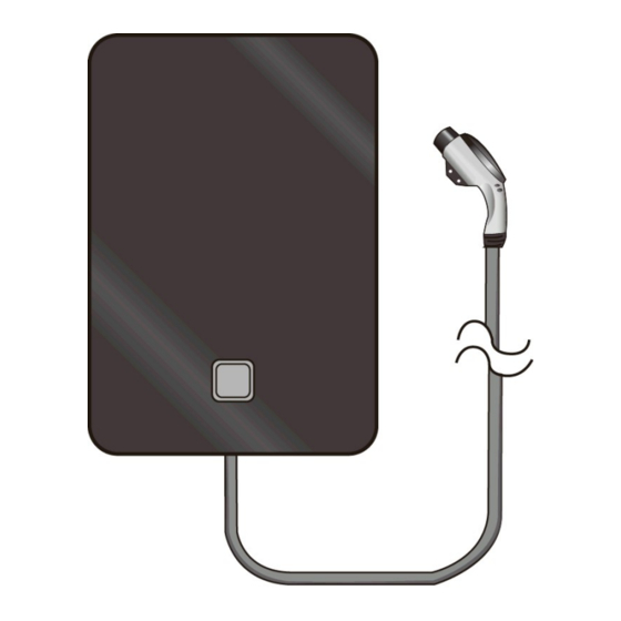
Page 54: The Ev Charger
The EV Charger LED indicator The EV Charger has a single, multi-color LED indicator used to show charging status and error conditions. The LED can display several patterns: Steady Rotating Pulsing Blinking Bouncing Copyright © 2020 IoTecha Corp. All rights reserved. - Page 55 Charging paused. Steady Retry authentication. If vehicle connected, unplug and re-plug vehicle. Orange Rotating Charger booting up Bouncing Cannot establish remote server connection. Charging is not possible. Steady Charger out of service. Copyright © 2020 IoTecha Corp. All rights reserved.
-
Page 56: Charging The Vehicle
While the charger prepares to charge, the LED may show blinking white. b. Once charging begins, the LED shows pulsing green. When charging is complete, the LED changes to steady green. Copyright © 2020 IoTecha Corp. All rights reserved. - Page 57 If the authentication fails, the LED shows steady orange. Unplug the vehicle and re-plug. b. When the authentication is successful, the LED shows pulsing white. c. Charging begins. The LED shows pulsing green. When charging is complete, the LED changes to steady green. Copyright © 2020 IoTecha Corp. All rights reserved.
-
Page 58: Troubleshooting
Charging has paused. Wait for charging to resume (green LED). Steady Authentication failed. Retry authentication. If vehicle connected, unplug and re- Orange plug. Bouncing Cannot establish remote server connection. Charging is not possible. Steady Charger out of service. Copyright © 2020 IoTecha Corp. All rights reserved. -
Page 59: Fact Sheet
Fact Sheet Copyright © 2020 IoTecha Corp. All rights reserved. -
Page 60: Ev Charger Fact Sheet
Certifications FCC Part 15 Class B Wiring – Standard 3-wire (L1, L2, G) Output Power (kW @ max A) 19.2kW (240VAC @ 80A) Input Cord Requirement Hardwire Charging plug SAE J1772 (80A) Copyright © 2020 IoTecha Corp. All rights reserved. - Page 61 Isolate the product from any electrical source before wiring or servicing it. Failure to follow this may lead to 80A (Factory Setting) 100A severe bodily injury or death. Copyright © 2020 IoTecha Corp. All rights reserved.
- Page 62 Copyright © 2020 IoTecha Corp. All rights reserved.
- Page 63 40-015P215001 Copyright © 2020 IoTecha Corp. All rights reserved.
Need help?
Do you have a question about the CCS-ACL2 and is the answer not in the manual?
Questions and answers