Advertisement
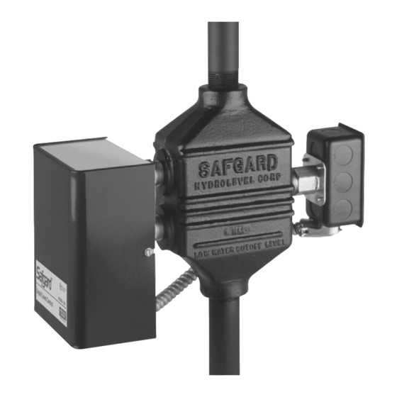
MODELS 250/250WC
Pump Control
Low Water Cut-Off
Combination
Operating Voltage ................. 120VAC
Max. Steam Pressure ............ 250PSI
Burner Relay ............. 10 FLA, 60 LRA
Pump Relay ................ 10 FLA, 60LRA
Alarm Relay ................ 10FLA, 60LRA
Power Consumption ................ 13 VA
The series 250 control requires regular maintenance for safe operation. Before installing
please read and understand the maintenance procedures listed on page 7 of this manual as
well as any required maintenance procedures listed in your boiler manufacturer's instructions.
Electrical shock hazard. To prevent electrical shock, death or equipment damage, disconnect power supply before installing
or servicing control. Only qualified personnel may install or service this control in accordance with local codes and ordinances.
Read instructions completely before proceeding.
Frozen pipes/water damage. Central heating systems are prone to shut down as a result of power or fuel outages, safety
related fault conditions or equipment failure. Installation of freeze protection monitoring or other precautions is recommended for
unattended dwellings in climates subject to sustain below-freezing temperatures.
Disconnect power supply before beginning installation to prevent electrical shock or equipment damage.
This low water cut-off must be installed in series with all other limit and operating controls installed on the boiler. After installation,
check for proper operation of all of the limit and operating controls, before leaving the site.
To prevent serious personal injury from steam and hot water make sure there is a discharge line from the blow-down valve to a
proper place of disposal.
To prevent a fire, do not use this low water cut-off to switch currents over 7.4A, 1/3 HP at 120 VAC or 3.7A, 1/3 HP at 240 VAC,
unless a starter or relay is used in conjunction with it.
Always install a new control on a new boiler system. Never use a control that has already been used on a previous appliance.
Failure to follow this warning could cause property damage, personal injury or death.
PLEASE READ BELOW BEFORE INSTALLING
Read and understand these instructions completely before installing or servicing this control. Save these instructions for
future reference.
Only qualified personnel may install or service the control in accordance with local codes and ordinances.
S econdary (redundant) Low Water Cut-Off controls must be installed on all steam commercial boilers. At least two con-
trols must be connected in series with the burner control circuit to provide redundant protection in the event the boiler
experiences a low water condition.
• No moving parts to stick, wear or hang-up
• No replacement or rebuilding of floats or mechanical parts
• Reliable electronic design
• Made in the USA.
WARNING
NOTICE
1
MODEL 250
MODEL 250WC
Advertisement
Table of Contents

Related Manuals for safgard 250


Summary of Contents for safgard 250
- Page 1 MODEL 250WC WARNING The series 250 control requires regular maintenance for safe operation. Before installing please read and understand the maintenance procedures listed on page 7 of this manual as well as any required maintenance procedures listed in your boiler manufacturer’s instructions.
-
Page 2: Installation: Mounting
Then, install a fully ported blow-down valve (and discharge line) directly below the lower cross of the water equalizing pipe. For best results, we recommend a dual valve blow-down system for the 250 Series Control. Gauge Glass Model 250WC is designed to have a gauge glass (not included) on the Low Water Cut Off Manifold (see diagram on page 6 for mounting location). -
Page 3: Installation & Wiring
DANGER The Safgard 250 is intended as a pilot duty control only and must be installed with a relay between it and both the condensate pump and burner circuit. Direct wiring of the control to either the burner circuit or condensate pump can result in failure of the control. -
Page 4: Typical Applications
PROBE DATA PROBE TEST PRESSURE 1000PSI TYPICAL APPLICATIONS Safgard 250 Pump Controller/LWCO combination 45-715 Feed Valve Assembly Safgard 270 High Water Limit/Alarm Safgard 727 Tank Control Safgard 550 or 750 as Secondary LWCO... - Page 5 DIMENSIONS and CONTROL LAYOUT — Model 250 LWCO MAXIMUM STEAM PRESSURE 250 PSI...
- Page 6 DIMENSIONS and CONTROL LAYOUT — Model 250WC LWCO...
-
Page 7: Service & Maintenance
Before Blow Down Blow-down the 250 Series Control when the burner is on and the water level is at its normal operating level [between middle (PUMP ON) probe and upper (PUMP OFF) probe, see diagrams on pages 5 and 6]. Confirm water is visible in the site glass. - Page 8 NOTES LIMITED MANUFACTURER’S WARRANTY We warrant products manufactured by Hydrolevel Company to be free from defects Company be liable for any other loss or damage, whether direct, indirect, incidental in material and workmanship for a period of two years from the date of manufacture or consequential.
Need help?
Do you have a question about the 250 and is the answer not in the manual?
Questions and answers