
Related Manuals for MTS Systems Level Plus STI

Summary of Contents for MTS Systems Level Plus STI
- Page 1 Sensors Division ® L e v e l P l u s T a n k G a u g i n g S y s t e m s Side Tank Indicator (STI) Installation & Operation Manual 0796 550436 Revision A...
- Page 2 GENERAL INFORMATION MTS PHONE NUMBERS To place orders: 800-457-6620 Application questions: 800-457-6620 Service: 800-457-6620 Fax: 800-943-1145 SHIPPING ADDRESS MTS Systems Corporation Sensors Division 3001 Sheldon Drive Cary, North Carolina 27513 HOURS Monday - Friday 7:30 a.m. to 5:30 p.m. EST/EDT...
-
Page 3: Table Of Contents
Section TABLE OF CONTENTS Page INTRODUCTION Specifications INSTALLATION Mounting The Enclosure Cable Requirements Recommended Cable Types How To Select Cables Field Wiring Installation Power Supply Requirements Switch Settings 2.7.1 Default Setting 2.7.2 DIP Switch #1 2.7.3 DIP Switch #2 (Stand-Alone Mode — Commands/# of Gauges) 2.7.4 DIP Switch #2 (Network Mode —... -
Page 5: Introduction
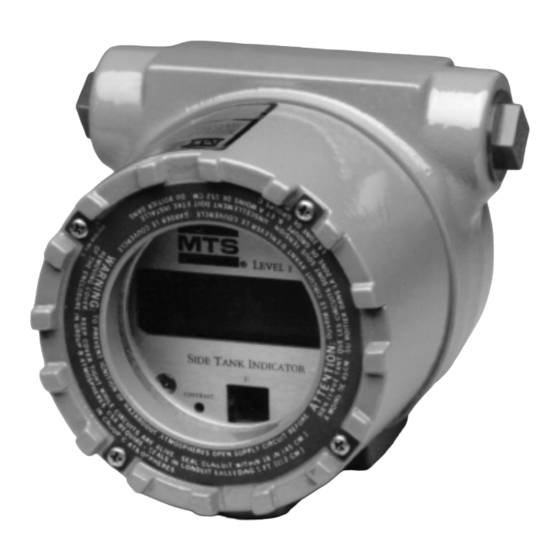
INTRODUCTION The Side Tank Indicator (STI) is part of the MTS Level Plus product ® line. It it offers a liquid crystal display (LCD) to indicate tank condi- tions, an EIA-485 serial interface and a NEMA 4 type enclosure. The LCD consists of sixteen seven-segment characters and thirty-one special icons that indicate various tank conditions. - Page 6 Other manuals: • Level Plus Tank Gauge Monitor Installation and Operation Manual (P/N 550421) • DDA Tank Gauge Installation and Operation Manual (P/N 550164) • Hand-Held Terminal (HT100) Operation Manual (P/N 550424) • LPS80 Installation and Operation Manual (P/N 550429)
-
Page 7: Specifications
1.1 Specifications Environmental: Operating Temperature: Electronics: -40 to 176°F (-40 to 80°C) LCD: 14 to 158°F (-10 to 70°C) Storage Temperature -40 to 185°F (-40 to 85°C) Humidity: 0% to 100% R.H.* Vibration: Shock: Mechanical: Enclosure: NEMA 4 (outdoor)* Mounting: Supported by rigid conduit or by cus- tomer provided bracket Entry Points:... -
Page 8: Installation
INSTALLATION STI installation has three phases: (1) mounting the enclosure, (2) wiring, (3) and setup. Each phase of installation will be discussed in detail. Guidelines will be presented for each phase. Before proceeding with the installation, identify the mode that you want the STI to operate in (i.e., Stand-alone or Network). -
Page 9: Mounting The Enclosure
2.1 Mounting The Enclosure Mount the STI on a flat, vertical surface. Choose a surface that is free from obstructions that would make viewing the display or removing the cover difficult. Also, take into account the location of the sun or other light sources and how it might affect the ability to view the LCD display clearly (without glare). - Page 10 CAUTION: Chico seals or cable glands are recom- mended to keep moisture that may be present in the wiring conduits from entering the STI enclosure. Before mounting, consult the National Electrical Code (NEC) and local electrical codes as necessary in reference to mount- ing NEMA 4 style enclosures.
-
Page 11: Cable Requirements
2.2 Cable Requirements The wiring connections for the DDA/STI system are based on an EIA-485 multidrop network as shown in Figure 2.3A and 2.3B. A typical network consists of the main wire trunk and individual tap connections to each STI display and DDA tank gauge. - Page 12 Power Intrinsic Safety Supply Barrier Figure 2.3B DDA/STI Network (Stand-alone mode) The capacitance of the cable also affects the network operation and must be considered when selecting cable for the network. The primary consideration is that the capacitance of the cable is an energy storage element and affects intrinsic safety aspects of the network.
- Page 16 Since the resistance of the cable is the dominant factor in determining the maximum cable length of the network, heavier gauge cables will allow longer cable runs. This is true because heavier gauge cables have lower resistance ratings per foot. For example, the resistance of a typical 22 AWG cable is 15 ohms per 1000 feet of cable where as 18 AWG cable is 6 ohms per 1000 feet of cable.
- Page 17 if both the cable selection (for the communications circuit) and the communications driver chip (from the host interface) meet the requirements as defined by the EIA-485 standard. The EIA- 485 standard states that cable for the communications circuit must have a nominal impedance of 120 ohms and be of the low capacitance type (less than 20 picofarads per foot).
- Page 18 26 Volt Power Supply w/STAHL Safety Barrier 8901/31-280/165/80 (Barrier Resistance = 201 ohms) Feet Meters 1219 1524 1829 2134 2438 Cable Distance (Maximum Permissible Cable Length = 8,000 ft.) 24 Volt Power Supply w/STAHL Safety Barrier 8901/31-280/165/80 (Barrier Resistance = 201 ohms) Feet Meters 1219...
- Page 19 26 Volt Power Supply w/MTL Safety Barrier MTL 728 (Barrier Resistance = 340 ohms) Feet Meters 1219 1524 1829 2134 2438 Cable Distance (Maximum Permissible Cable Length = 8,000 ft.) 24 Volt Power Supply w/MTL Safety Barrier MTL 728 (Barrier Resistance = 340 ohms) Feet Meters 1219...
- Page 20 26 Volt Power Supply w/P&F Safety Barrier Z428/Ex (Barrier Resistance = 327 ohms) Feet Meters 1219 1524 1829 2134 2438 Cable Distance (Maximum Permissible Cable Length = 8,000 ft.) 24 Volt Power Supply w/P&F Safety Barrier Z428/Ex (Barrier Resistance = 327 ohms) Feet Meters 1219...
-
Page 21: Recommended Cable Types
2.3 Recommended Cable Types This section lists recommended cable types for the STI power supply, communications, and back light (optional) circuits. The following lists do not include all possible cable types and man- ufacturers. The lists should be used only as a guideline when choosing cables. - Page 22 Wire Size Capacitance Manufacturer Cable # NOTES (AWG) (Pf/foot) ALPHA 2471 (16 AWG ok) BELDEN 8760 BELDEN 9460 CAROL C2536 (16 AWG ok) CAROL C2521 DEKORON 1T52-8820T BELDEN 8762 BELDEN 9464 CAROL C2519 CAROL C2520 MANHATTAN M39047 DEKORON 1T52-0810T ALPHA 6072 (extra wire pair) BELDEN...
- Page 23 Recommended Single Pair Cable Types - Communications Circuit General requirements: • Shielded twisted pair • 24 picofarads per foot or less. See note below • Nominal impedance range - 100 to 150 ohms • Insulation thickness: 0.10 in. (0.25 mm) minimum NOTE: For the communications circuit, the shield is terminated independently at the...
- Page 24 Recommended Multiple Pair Cable Types - Power Supply, optional Backlight Circuit & Communication Circuits NOTE: Requires 3 pair cable if using optional backlight circuit. General Requirements: • Individually shielded, twisted pair, 2 or 3 pairs • 24 picofarads per foot or less. See note below •...
-
Page 25: How To Select Cables
NOTE: Most cable manufactures do not list inductance properties for cables. Where the inductance properties are unavail- able, ISA RP12.6 (Installation of Intrinsically Safe Instrument Systems in Class Hazardous Locations) recommends the use of 0.2uH (micro henries) per foot as a value for cable inductance. 2.4 How To Select Cables The steps and criteria used for selecting cables for an intrinsically safe DDA/STI network are outlined below. - Page 26 3. Determine the power supply voltage that will be used for the devices on the network. The available choices are limit- ed to 24 volts and 26 volts (DC). As indicated by the cable selection graphs, the larger the power supply voltage will allow more devices on the network and/or longer cable lengths.
- Page 27 7. Calculate the maximum network capacitance for each circuit (power supply, optional backlight, and communications). Include the capacitance of the cable and the capacitance of each device on the network. The capacitance of each net- work tap connection must also be included in the total cable capacitance.
- Page 28 EXAMPLE CABLE SELECTION Assumptions: • 10 DDA tank gauges and 10 STI displays on network • 2000 ft. cable length • 20 network tap connections at 50 feet each (1000 ft. total) • 24 Vdc power supply STEP 1. Determine the maximum number of devices (DDA tank gauges and STI displays) connected to the network.
- Page 29 Intersection Point Feet 1219 1524 1829 2134 2438 Meters Cable Distance (Maximum Permissible Cable Length = 8,000 ft.) 24 Volt Power Supply w/ STAHL Safety Barrier 8901/31-280/165/80 (Barrier Resistance = 201 ohms) Figure 2.7 Cable Selection NOTE: If a cable selection cannot be found to the right of the intersection point, then the number of devices or the length of the cable must be reduced to move the inter-...
- Page 30 STEP 5. Select cables from the recommended cable list that meet the capacitance specifications for the power supply cir- cuit, optional backlight circuit, and the communications circuit. For the power supply circuit and backlight circuit, the cable capacitance must be 50 picofarads per foot or less. Assuming 20 AWG wire size, the cable lists show six cable selections with a capacitance of 50 picofarads or less.
- Page 31 STEP 6. Calculate the maximum network capacitance for each circuit (power supply, backlight, and communications). For the power supply circuit (and optional backlight circuit): Ca(barrier) > C(cable) + C(devices) C(device) = 1600 picofarads per DDA tank gauge or STI display For the communications circuit: Ca(barrier) >...
- Page 32 Since the communication circuit capacitance of 0.146 µF is less than the maximum allowed for the STAHL communication cir- cuit barrier (7.8µF), the communication circuit meets intrinsic safety requirements with respect to capacitance. NOTE: If the preceding equations cannot be met, then the cable length must be reduced or another cable type must be used.
- Page 33 Since the power supply circuit inductance of 0.6 mH is less than the maximum allowed for the STAHL power supply circuit barrier (5.1 mH), the power supply circuit and backlight circuit meets intrinsic safety requirements with respect to inductance. For the communications circuit using BELDEN 83393 cable: L(cable) = (3000 feet) * (0.2 µH/foot) = 600 µH = 0.6 mH L(devices) = 0 mH L(total) = 0.6 mH...
-
Page 34: Field Wiring Installation
2.5 Field Wiring Installation Where applicable, cable installations must meet the require- ments of an intrinsically safe (I.S.) system installed in haz- ardous locations. In addition to the capacitance and inductance of the cable (see Section 2.2), the designer and installer of an I.S. - Page 35 4. Cable splices - All cable splices within the network wiring should be protected by seals and/or terminal boxes. All con- nectors or terminal hardware should be of non-corrosive type and attached to the wires using crimp or crimp and sol- der (preferred) techniques.
- Page 36 If not already removed, remove the electronics module from the STI enclosure. Place it in a safe place such as the shipping carton that the STI was received in. Refer to MTS drawing #650597 in this section for a detailed view of the P1/P2 termi- nal block.
-
Page 38: Power Supply Requirements
2.6 Power Supply Requirements The power supply voltage regulation for a DDA/STI system is not critical since each DDA/STI incorporates on board regula- tion. Both the DDA and STI are designed to tolerate changing voltage levels at the power supply terminals which result from changing load conditions which result in voltage drops across the safety barriers. -
Page 39: Switch Settings
2.7 Switch Settings The STI has three switches. To access these switches, first remove the cover from the enclosure by rotating it counter clockwise. The three switches are located on the display PCB at the top of the assembly. The face plate has a cut-out area to allow access to these switches. -
Page 40: Dip Switch #1
Reset Switch Figure 2.8 Default Switch Settings 2.7.2 DIP Switch #1 (SW1) This switch serves the same function in both Stand-alone and Network modes. It is used to set the power override and mode of operation as well as setting the Communications Time-out Timer (CTT), Data Error Detection (DED), Temperature Units, and Level Units. - Page 41 SW1.2 - Mode: To operate the STI in Stand-alone mode, place this switch in the OFF position. See Section 3.1 of this manual for more details on operating the STI in Stand-alone mode. To operate the STI in Network mode, place this switch in the ON position.
- Page 42 point will come on to indicate a negative number. 2.7.3 Dip Switch #2 (SW2 - Stand-alone mode) When the STI is set for Stand-alone mode, SW2 sets the num- ber of DDA tank gauges to be scanned and the DDA command to be sent to each gauge.
- Page 43 SW2.1 Set number of DDA gauges to scan Scan one DDA gauge using STI command 0 (i.e. custom command table; see section 3.1 for STI/DDA Command Set DDA gauge Reference chart) command number SW2.6 SW2.1 Scan two DDA gauges using STI command 1 (level 1) SW2.6 SW2.1...
-
Page 44: Dip Switch #2 (Stand-Alone Mode - Commands/# Of Gauges)
2.7.4 Dip Switch #2 (SW2 - Network Mode) When the STI is set for Network mode, SW2 serves as the net- work address decoding switch. Each STI in Network mode requires a unique address. The address is decoded as a binary offset from the base address of 80 hex. -
Page 45: Push Button Switch #3
NOTE: In Network mode, the address switch decoding circuitry interprets the address switch positions opposite to the ON label on the switch housing. For example, switches SW2.1 through SW2.6 in the ON position are read as binary 0, establish- ing the base STI communication address of 80 hex (128 decimal). - Page 46 be addressed as C0 hex. Each additional DDA gauge must have an incremental address (i.e., second DDA must have the address C1 hex, etc.). See the DDA tank gauge opera- tion manual for more information regarding the DDA tank gauge. 3.
-
Page 47: Display Contrast Adjustment
2.9 Display Contrast Adjustment The LCD display contrast (darkness) can be adjusted using the contrast adjustment screw located on the lower left section of the display panel. Turn the adjustment screw counterclockwise to lighten the LCD display and clockwise to darken the display. LEVEL PLUS SIDE TANK INDICATOR Access hole to... -
Page 48: Operation
OPERATION This section describes the operation of the STI in both Stand-alone and Network modes. Command protocol and network timing issues are also discussed. Note that the DIP switch SW2 has a different function depending on the mode selected (Stand-alone or Network mode). This section makes references to the DDA tank gauge manual and the DDA Level Plus Monitor manual. - Page 49 Message Meaning RESET This message indicates that the microprocessor is in a state of reset. This can occur when: 1.) Power is applied 2.) Reset switch (SW3) has been depressed. 3.) Watchdog timer circuit not strobed by the microprocessor within specified time frame. 4.) The +5 V supply goes out of tolerance.
- Page 50 be used with the custom command table. If you want to use different commands for different gauges you must use the cus- tom command table. Use STI command 16 hex to write the commands to the command table. Use command 11 hex to read the custom command table.
-
Page 51: Network Mode
than the high set point value, the “HI” icon for that level or temperature comes on. The overall scan rate of the STI in Stand-alone mode depends on the commands being sent to DDA gauges, the scan delay time programmed into the STI scan delay control code, and the number of DDA gauges that the STI is polling. - Page 52 host device based on the specific application. It must have the capability to be programmed to work with the STI device pro- tocol. Refer to the users manual for the particular host device or software package for information on how it can be used with an STI display.
-
Page 53: General Network Mode Protocol Information
3.3 General Network Mode Protocol Information The STI display is designed to function in an intrinsically safe EIA-485 network allowing up to 20 devices to be multi- dropped on one communication line. A device can be a DDA tank gauge or an STI display. The network requires a four wire interface to provide both power and communications to each of the devices located in the hazardous area. - Page 54 Example 1 - Serial data transmission format 0 X X X X X X X X P 1 0 X X X X X X X X P 1 - Start Bit 0 X X X X X X X X P 1 - D1 Bit 0 X X X X X X X X P 1 - D8 Bit 0 X X X X X X X X P 1 - Parity Bit 0 X X X X X X X X P 1 - Stop Bit...
- Page 55 mand (from the previous interrogation sequence) will remain in the command buffer. The STI hardware can not determine if the current command was possibly rejected. The host comput- er must then verify if the correct command was received by reading the echo of the address byte and command byte sent by the STI display.
- Page 56 The STI display will respond by transmitting its own local address and the command that was received from the host. This serves two purposes. The first being a simple identifica- tion that the correct STI received the correct command and that it is currently active.
- Page 57 All STI display commands support a checksum calculation mode that allows the STI to check the integrity of transmitted data from the host device. The actual checksum value that is transmitted is the compliment (2’s compliment) of the calculat- ed value. The checksum scheme is based on a 16 bit summa- tion of the data within the transmitted block (including all con- trol characters) without regard for overflow.
- Page 58 <STX> and <ETX>) as shown above. The result in this example is 0308 Hex. Then convert the decimal ASCII checksum value back to Hex (i.e. 64760 to FCF8 Hex). Add the Hex summation value to the Hex checksum value and the result will be zero (disregarding overflow) for uncorrupted data.
-
Page 59: Network Mode Timing Considerations
3.4 Network Mode Timing Considerations The DDA/STI network has several timing constraints to be con- sidered when designing and coding communication drivers. The DDA/STI network follows the EIA-485 standard which defines a multi-drop communication interface that uses differ- ential drivers and receivers operating in a half duplex mode. In this configuration each driver and receiver are wired together as shown in Figure 3.1. - Page 60 straints are imposed on the protocol to eliminate multiple devices from transmitting data simultaneously. NOTE: Many available communications cards (line drivers) for use with the host device use a special control line input to control the enabling and disabling of the EIA- 485 driver.
- Page 61 2. After the driver is enabled, the host performs a small time delay, shown here as t1, to let the communication lines transition from a high impedance state to an active (enabled) state. This typically requires no more than 1 millisecond. If the communication lines are extremely long, additional time may be required due to additional cable capacitance.
- Page 62 transmitting data, the maximum delay for t5 then is 13.7 mil- liseconds. NOTE: If t3 is less than 5 milliseconds, then the maximum delay for t5 can be extended by the difference (5 milliseconds - t3 actual). 5. The STI will begin to transmit the address/command echo in 28 (±...
- Page 63 11. Period t15 is the time required for the STI to transmit the STI acknowledged sequence. If the received command was accepted, the STI will transmit the ACK character (06 Hex) followed by the optional 5 character checksum (6 characters total).
-
Page 64: Command Protocol
3.5 Command Protocol The commands for STI displays work much the same way as the commands for DDA tank gauges. For an STI to respond to a command, the STI must be operating in the Network mode. If you have an STI working in Stand-alone mode and you want to change an alarm set point for instance, you must first config- ure it for Network mode. - Page 65 Command Set 1 - 00 Hex to 07 Hex (Special Control Commands) Command 00 Hex - Module disable command Issuing this command will force an active module to be dis- abled (go to sleep mode). This command does not need to be preceded by an address byte and can only be issued when there is no communication activity on the network.
- Page 66 Command set 2 - 08 Hex to 0C Hex (Test Mode Commands) STI test commands consist of two components (or data com- munication sequences). The first component of any test com- mand consists of the usual <addr><command> data necessary to activate the respective STI module. The second component consists of a special access code for each test command.
- Page 67 STI Response (after completion and test failed) Data Format - <NAK>Exxx<ETX>ccccc - <NAK> is the ASCII 15 hex. This character is sent by the STI module to confirm to the host that the test was not successfully completed (error detected). - Exxx is the general format for STI error codes.
- Page 68 Command 0A Hex - Not defined Command 0B Hex - Communication hardware test The STI module will output the following characters during this test (47 characters total): <SOH><STX><ETX><EOT><ENQ><ACK><NAK>ABCDFGHIJKLMNOPQRSTU- VWXYZ.0123456789-: The last character will be a blank space. A final <ACK> or <NAK>E908 will follow along with the optional five character checksum.
- Page 69 Command set 3 - 0D Hex to 12 Hex (High Level Memory Read Commands) For command set 3, simply issue a <address><command> sequence and the STI will respond with the echoed address/command. The requested information will follow in the format for any given command as shown. Command 0D Hex - Read LOW alarm limits Alarm limits apply to Stand-alone mode only.
- Page 70 Command 0E Hex - Read HIGH alarm limits Data Format - <STX>ddd.dd:ddd.dd:ddd.dd:..<ETX>ccccc - <STX> is ASCII value 02 hex - Variable length record containing 24 fields. Each field is separated by a colon. Data in each field contains one to three characters to the left of the decimal and two characters to the right.
- Page 71 Command 10 Hex - Read firmware control code Some of the individual control codes described here work in conjunction with SW1. See Section 3.7.1 of this manual for additional information on how the firmware control code works, and how to use it. Data Format - <STX>d:d:d:d:d:d:d:d<ETX>ccccc - <STX>...
- Page 72 Command 11 Hex - Read custom DDA command table This command returns the list of DDA commands stored in the custom command table. This command table can only be used by the STI when it is in the Stand-alone mode and SW2 is set to read commands from the custom table.
- Page 73 Command 13 Hex - Write firmware control code Host issued command (part 1) Data format - <address><command> - <address> is the address (80 hex to BF hex) of the STI - <command> is the STI memory write command After the address and command byte are transmitted by the host, the addressed STI module will “wake up”...
- Page 74 STI module response - successful memory write. Data Format - <ACK>ccccc - <ACK> is ASCII 06 hex. This character is sent by the STI module to confirm to the host that the EEPROM memory write cycle was completed successfully. - Optional five character checksum STI module response - unsuccessful memory write.
- Page 75 Command 14 Hex - Write LOW alarm limits Alarm limits and the alarm message control function can only be used in STI Stand-alone mode. Host issued command (part 2): Data Format - <SOH>n:c:ddd.dd<EOT> - <SOH> is ASCII 01 hex - Variable length record with three data fields. The first data field is one byte long and contains the gauge number (1 to 8) where the new low alarm limit will be written to.
- Page 76 Command 16 Hex - Write custom DDA command table. This command is used to write custom DDA commands to the command table. The command table is only used in Stand- alone mode. Commands must be written as an ASCII represen- tation of the command in decimal (rather than hex).
- Page 77 Data types Displayed Command displayed Resolution (HEX) (DECIMAL) Level 1 0.1 inch Level 2 0.1 inch Level 1, Level 2 0.1 inch Level 1, Level 2, 0.1 inch Avg. Temp Level 1 0.01 inch Level 2 0.01 inch Level 1, Level 2 0.01 inch Level 1, Level 2, 0.01 inch...
- Page 78 one second, and the communications time out timer is enabled, the STI will cancel the current command and go back to sleep mode. If the second part of the command is not received in the proper format, the STI module will transmit a <NAK>...
- Page 79 EXAMPLE 1: <SOH>100.00:200.00:33.3<EOT>ccccc This example displays level 1 as 100.00 with the LEV1 icon on, display level 2 as 200.00 with the level 2 icon on and display temperature as 33.3 with the TEMP icon on. Optional check- sum is shown. Figure 14 shows how the STI display should appears after transmitting this example to it.
- Page 80 NOTE: Only ASCII data characters 0 through 9 , : (colon), . (decimal point), - (negative sign), <SOH> (ASCII 01 hex) and <EOT> (ASCII 04 hex) are allowed with LCD data write commands 18 and 19. STI module response - LCD data write successful Data Format - <ACK>ccccc - <ACK>...
- Page 81 The remaining descriptions for the other LCD data write com- mands will include only the data format for part 2 of each host issued command. Command 19 Hex - Write level and temperature data with LCD ICON con- trol codes. Host Format - <SOH>ddd.dd:ddd.dd:ddd.d:ddddd<...
- Page 82 °F LEV1 HILO LEV2 HILO TEMP Figure 3.5 - Example 3 LCD Display (Auto Format Mode) Commands 1A Hex and 1B Hex - Reserved Command set 6 - 1C Hex to 1F Hex (LCD Write Commands - Manual Format Mode) Descriptions for LCD data write command is this section include only the data format for part 2 of each host issued command.
- Page 83 EXAMPLE 4: <SOH>1234567890123456<EOT>ccccc TEST °C °F ERROR SCAN 1 2 3 4 5 6 7 8 LEV1 HILO LEV2 HILO TEMP HILO Figure 3.6 - Example 4 LCD Display (Manual Format Mode) EXAMPLE 5: <SOH>~~~1234567890~~~<EOT>ccccc NOTE: Blank spaces are shown as the character “~”...
- Page 84 Command 1D hex - Write 16 character data to LCD (with icon control field) Host issued command (part 2): Data Format -<SOH>dddddddddddddddd:eeeeeeee<EOT>cccccc - <SOH> is ASCII 01 Hex - This fixed length data record contains two fields. The first field has a fixed length of 16 characters. It should be padded with the space character (ASCII 20 hex) if necessary.
- Page 85 point will be on. - <EOT> is ASCII 04 hex. - Optional five character checksum.
-
Page 86: Lcd Display And Optional Back Light
3.6 LCD Display and Optional Back Light The STI uses a custom Liquid Crystal Display (LCD) for dis- playing information. The LCD consists of sixteen seven-seg- ment characters and thirty-one special icons. The seven seg- ment displays can display the following characters: blank, “-”, “0”... -
Page 87: Programming The Sti
Reed Switch Magnet Location Figure 3.9 - Reed Switch Location In non-intrinsically safe applications, the backlight can be enabled all the time by setting an internal jumper. Contact the factory for additional information about enabling the backlight continuously. The LCD contrast is adjustable. To make contrast adjustments, the cover must first be removed. -
Page 88: Programming Control Code And Mode Switch
The HT100 device (available from MTS sensors) is a hand held terminal which allows the user to program and troubleshoot both the DDA gauge and the STI display. It also simplifies the programming of an STI. You do not have to type in the address/command sequences or any control codes. - Page 89 Control code element #2 - This code is used in conjunction with SW1.4 and controls the Communications Time-out Timer (or CTT) function. The purpose of the CTT is to shut down the STI (when operating in Network mode) if a communications sequence does not take place within a specified period of time (1.0 second).
-
Page 90: Programming Alarm Setpoints
Control code elements #5 to #8 - Reserved for future use. These control code locations should always be written as a “0”. 3.7.2 Programming Alarm Setpoints Alarm set points are functional only if you are operating in the STI Stand-alone mode and if the alarm message function is enabled (see previous section). -
Page 91: Error Codes
3.8 Error Codes All communication and display error codes are preceded by a capital letter “E” (ASCII 45 hex) and are in the form Exxx where “xxx” can be any number shown below. The error codes used by the STI are different from those used by the DDA gauge. - Page 92 E904 - EEPROM CHECKSUM TEST FAILED The STI EEPROM data checksum test has failed. E905 - LCD DRIVER IC COMMUNICATION FAILURE The internal LCD IC is not communicating with the microprocessor E906 - EXTERNAL I/O IC NOT COMMUNICATING WITH MICRO PROCESSOR The external I/O IC is not communicating with the microprocessor.
-
Page 93: Troubleshooting And Maintenance
TROUBLESHOOTING AND MAINTENANCE After the initial installation and validation of a DDA/STI system, no scheduled maintenance is required, except occasional cleaning of the glass front of the enclosure. However, it is accepted practice to perform periodic inspection to verify that the intrinsic safety of the system and associated equipment is maintained. - Page 94 Field wiring problems are likely to be the most often encountered problems associated with a DDA/STI network. The list of problems associated with field wiring can typically be grouped into two cate- gories: prestart-up and poststart-up problems. Many prestart-up prob- lems are often caused by: •...
-
Page 95: Cable Isolation And Connectivity Tests
CAUTION: Always verify power is OFF before installing or removing the Micro-proces- sor / Display “module”. Use caution when handling this assembly. Use static sensitive device handling procedures. Do not allow contaminants to enter the assembly while it is removed from the housing. - Page 96 1. Make sure all power supplies are and computer devices connected to the network are OFF. 2. Remove the STI cover. Remove the electronics module. Disconnect the positive power supply lead from the STI dis- play at terminal block P1-1. 3.
-
Page 97: Using Built-In Diagnostics
Minimum Nominal Maximum Power override ON 10.0 mA 14 mA 20.0 mA Power Override OFF 1.0 mA 1.3 mA 1.6 mA Back Light 25 mA 55 mA 65 mA 4.3 Using Built-in Diagnostics There are built-in diagnostic functions in the STI that can be used to test certain features of the electronics. - Page 98 RAM Test (command 08 Hex) - Tests the Random Access Memory (RAM) on the STI Microprocessor board. RAM is tested by applying alternate patterns of 055 hex (0101 0101 B) and 0AA hex (1010 1010 B) to each byte of memory and then read the value written back and verify it to be correct.
-
Page 99: Replacing Printed Circuit Boards
4.4 Replacing Printed Circuit Boards If troubleshooting results reveal that the electronics have been damaged, they will need to be replaced. Replacement of the module can easily be done in the field by any qualified instru- ment technician. CAUTION: Always verify power is off before installing or removing the Microproces- sor / Display “module”. -
Page 100: Upgrading Firmware
4.5 Upgrading Firmware If future firmware revisions are issued, you may want to upgrade your current firmware. This may allow you to take advantage of new features, commands, etc. The firmware is the “program” that operates the STI and it is contained on one 32 pin PLC device. -
Page 101: Appendix A - References
APPENDIX A: Standards/Publications with information on the installation and maintenance of intrinsically safe systems. Reference Standards: • ANSI/ISA - RP12.6 — Installation of intrinsically safe systems for hazardous loca- tions. • NFPA 493 — Standard for intrinsically safe apparatus and associated apparatus for use in Class I, II and III Division 1 hazardous locations. - Page 103 Japan Fax: 800-943-1145 Fax: 011-49-2351-56491 Telephone: 011-81-45-475-2401 Fax: 011-81-45-475-0641 ISO 9001 C E R T I F I E D Level Plus is a registered trademark of MTS Systems Corporation. 7/96 550436 Revision A DAP © MTS Systems Corporation, 1996...
Need help?
Do you have a question about the Level Plus STI and is the answer not in the manual?
Questions and answers