Table of Contents
Advertisement
Quick Links
Advertisement
Table of Contents

Subscribe to Our Youtube Channel
Summary of Contents for ECKELMANN VDD 500
- Page 1 Operating instruction Temperature Display Virtus Data Display 08.11.2022 Doku 1.1...
- Page 2 Copyright: All rights to any use whatever, utilisation, further development, forwarding and creation of copies remain with the Eckelmann AG company. In particular, neither the contract partners of Eckelmann AG nor other users have the right to distribute or market the IT programs/program parts or modified or edited versions without express written permission.
-
Page 3: Table Of Contents
2.5.1 ESD - Rules for handling and working ......................9 Abbreviations used .............................9 VDD 500 Functions............................10 Comparison of VDD 500 versus BT 30 ....................12 Installation and start-up VDD 500 ......................14 Limitations UA 400 E / UA 401 E / UA 410 E....................16 Connection - Terminal assignment VDD 500 ..................17... -
Page 4: Conventions
1 Conventions 1.1 Warning Signs and Symbols Employed Explanation of the warning signs, symbols and text formatting used in this operating and service manual: • DANGER DANGER Instructions with this symbol and/or the signal word DANGER warn the user of situations that will cause severe injury or death if the specified instructions are not observed! * •... -
Page 5: Explanation Of 'Safety Instructions And Hazard Warnings
A general instruction consists of two elements: The symbol with text (including NOTICE, if applicable) and the text of the instruction: For example: NOTICE The current operating manual is available online from the E°EDP (Eckelmann ° Electronic Documentation Platform) at www.eckelmann.de/elds. 08.11.2022 5/23... -
Page 6: Safety Instructions
2 Safety instructions This operating manual is part of the device. It must be kept in the vicinity of the controller as well as for future use so that it can be consulted when required. The operating manual must be available to the operating and maintenance personnel at all times in order to avoid operating errors. -
Page 7: Disclaimer In The Event Of Non-Compliance
ATTENTION Warning of damage to goods! In our experience, the transmission of fault messages is not yet functional during the putting into service (no internet connection, no telephone line installed, etc.). It is strongly recommended in such cases to monitor the controller via the CAN bus using a system centre, a store computer or an operator terminal and to enable the transmission of fault messages, for example using a GSM modem via a mobile telephone system. -
Page 8: Intended Use
2.3 Intended Use The VDD 500 is designed for use as a temperature display and for use in commercial and industrial refrigeration facilities in accordance with the functional parameters and environmental conditions described in the instruction manuals. Read the safety instructions and the instructions for installation and putting into service, operation and maintenance. THEN start the commissioning and/or operation of the machine / system. The safety and functionality of the machine / system are only guaranteed for this intended application. -
Page 9: Electrostatic Sensitive Devices (Esds)
Containers and worktops made of wood, metal or conductive plastics or paper bags 2.6 Abbreviations used • DGUV Regulation 3 - Accident Prevention Regulation for Electrical Systems and Equipment (previously: BGV A3 - Employer’s Liability Association Regulation for Occupational Health and Safety) • DIN Deutsches Institut für Normung e.V. (German Standardisation Institute) • E°EDP/EDP Electronic Documentation Platform of Eckelmann AG • ESD Electrostatic-Sensitive Device • ESD Electro-static discharge (Electro Sensitive Devices) • IEC International Electric Committee •... -
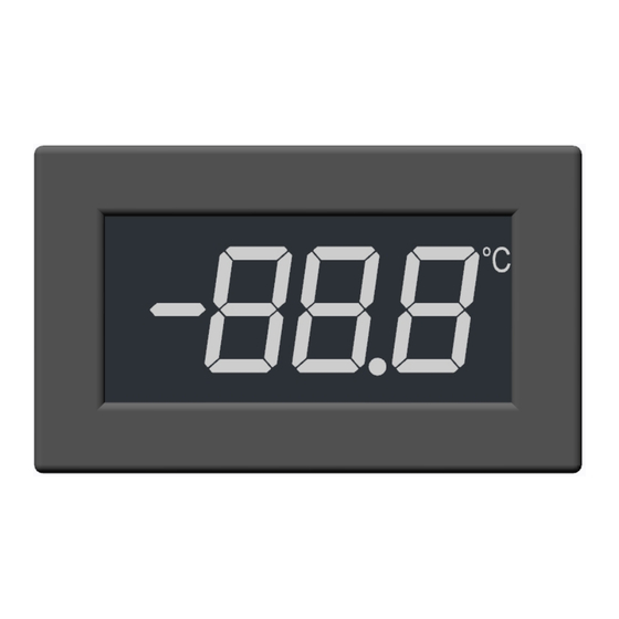
Page 10: Vdd 500 Functions
3 VDD 500 Functions The white backlit LED temperature display VDD 500 (Virtus Data Display) has been developed for front installation, e.g. in refrigerated case panels. The display shows the temperature of an assigned temperature sensor from one of two temperature zones in the range between -50 °C..+100 °C and the current defrost/alarm status. - Page 11 - Up to max. 4 temperature displays can be connected to the DISPLAY interface. - Max. 30 m cable length (longer distances on request). - Cannot be used simultaneously with BT 300 and/or BT 30 - The case controller and the connected VDD 500 can only be configured using a system centre connected on the CAN bus. For details, see chapter Limitations UA 400 E / UA 401 E / UA 410 08.11.2022...
-
Page 12: Comparison Of Vdd 500 Versus Bt 30
3.1 Comparison of VDD 500 versus BT 30 VDD 500 BT 30 (for details, see operating manual BT 30 / BT300) Dimensions 62 x 29,4 mm, for details, see chapter Technical Data 62 x 37 mm VDD 500... - Page 13 1x terminal block for looping through the shield. Alternative: Cable ties Cable length Max. 30 m: 1..4x VDD 500 Max. 480 m: 1x BT 30 and 1x BT 300 Note: BT 300 cannot be used simultaneously for system Max.
-
Page 14: Installation And Start-Up Vdd 500
The temperature displays VDD 500 are only compatible with case controllers with 9-pole DIP switch (B) and version V3.20 or higher, the current firmware for the UA 4xx E is available in the EDP. The temperature displays VDD 500 can only be configured using a system centre (E) connected on the CAN bus! Switch off controller, disconnect from the power supply (A). - Page 15 7. After the "VDD Scan", the temperature sensors of the case controller can now be assigned to the connected temperature displays VDD 500. Practical tip: In practice, two temperature displays - one for each temperature zone - are usually used to display the return air temperatures R4.1 and R4.2 (F).
-
Page 16: Limitations Ua 400 E / Ua 401 E / Ua 410 E
• Cannot be used simultaneously with BT 300 and/or BT 30. • The case controller and the connected VDD 500 can only be configured using a system centre connected on the CAN bus. Practical tip: Configuration of a case controller UA 4xx E with an operator interface BT 300 - if necessary, connection of BT 30... -
Page 17: Connection - Terminal Assignment Vdd 500
• At the last temperature display VDD 500 (F) or at the end of the cable, a terminating resistor of 120 Ohm* must be connected between terminals A- and B+ using TWIN wire end sleeves, the shield remains in the cable. - Page 18 • The assignment and colour sequence of the connector pin assignment of the temperature display VDD 500 is different from that of the system centres Virtus 5 / CI 5xx0 / CI 4xx0 / and the pack controller VPC 5000.
- Page 19 Examples for connection of VDD 500 to UA 4xx E • Variant 1: Case controller UA 400 E / UA 410 E Two temperature zones - Standard One temperature display per zone, e.g. for return air (R4.1/R4.2) •...
- Page 20 Practical tip / recommendation: If the temperature displays VDD 500 are already installed in a refrigerated case at the factory, two 4-pole terminal blocks should be provided there to loop through the cabling for easier connection: A: The cabling comes from the DISPLAY interface of the case controller or from another temperature display VDD 500.
-
Page 21: Decommissioning And Disposal
Users have the option of returning a B2B device distributed by us to us at the end of its service life. Please contact your customer service representative at Eckelmann AG to arrange for the device to be taken back and disposed of properly. Please inform yourself about the local regulations for the separate disposal of electrical and electronic products and batteries. -
Page 22: Technical Data Vdd 500
7 Technical Data VDD 500 VDD 500 Electrical data Operating voltage Via DISPLAY interface of the case controller. For supported controllers, see chapter VDD 500 Functions. Data interface Display range of the temperature -50 °C ... +100 °C... -
Page 23: Part Numbers And Accessories
• 1x terminating resistor 120 Ohm The temperature displays VDD 500 are only compatible with case controllers with 9-pole DIP switch and version V3.20 or higher, the current firmware for the UA 4xx E is available in the EDP.
Need help?
Do you have a question about the VDD 500 and is the answer not in the manual?
Questions and answers