
Summary of Contents for Uniphos 500DT
- Page 1 UNIPHOS–500DT Digital Transmitter INSTRUCTION MANUAL Uniphos Envirotronic Pvt. Ltd. Readymoney Terrace, 167, Dr. Annie Besant Road, Worli, Mumbai - 400 018. India 1 of 33...
-
Page 2: Table Of Contents
INDEX PG NO. A. Introduction: B. Installation: Overview Selecting Location Mounting guideline Installation 4-20mA Loop installation Relay Cable guideline Power Supply & Signal (4-20mA) Settings C. Operation: Gas alarm Conditions & Advice Fault alarm Conditions & Advice D. Calibration: Guidelines Calibration procedure Calibration Diagnostics Protection Important Notes... - Page 3 The product must not be used, if the function test is unsuccessful, it is damaged, a competent servicing/maintenance has not been made, genuine UNIPHOS spare parts have not been used. Remove and reinstall sensors carefully, ensuring that the components are not damaged; otherwise the...
-
Page 4: Introduction
A. Introduction: UNIPHOS range transmitters provide comprehensive monitoring of flammable, toxic & Oxygen gas hazards in potentially explosive atmosphere, both indoor & outdoor. “Uniphos-500DT” KwikSense-Lite transmitter provides continuous monitoring of the atmosphere for hazardous gases in the workplace virtually maintenance-free. - Page 5 Modular design this product helps user have ease installation, operations & maintenance throughout the product life. It has integral mounting plate consisting of four holes on the transmitter body for easy mounting. The transmitter may be fixed directly to a surface on the walls or similar support structure. On activation of the power supply to the transmitter;...
-
Page 6: Installation
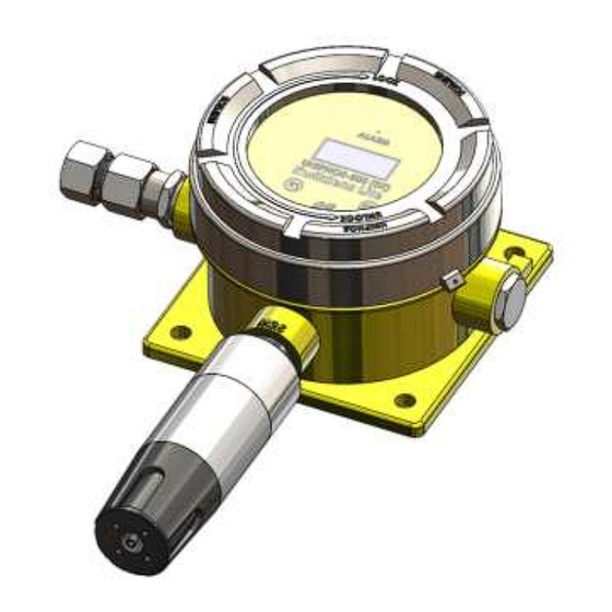
B. Installation Various parts of the gas transmitter are shown in the following diagram. Figure 1. 500 DT Transmitter overview 6 of 33... -
Page 7: Selecting Location
Selecting Transmitter Location: Select the most suitable locations for each transmitter. Several factors should be considered when selecting location to install the transmitter. following general suggestions should considered. • Air current: if there are fans, wind or other sources of air movement, gases may tend to rise or collect in certain areas of a facility. -
Page 8: Mounting Guideline
Mounting Guideline: Modular design of the product simplifies the installation procedure. The Transmitter unit has two electronic circuit boards Viz. main processor board & relay board. Power supply & signal (4 -20 mA) connector is located on the bottom Relay board. NO-C-NC contacts of all the three Relays are provided on the green connectors located on the one side of the bottom board. - Page 9 Figure 2. Outline drawing. (Front & side views with outline dimensions) 9 of 33...
-
Page 10: Installation
250 ohm. The signal range from the controller to the transmitter takes into account the return loop. Note: The Uniphos-500 Series Controllers have a resistance of 100 ohm maximum. Maximum cable lengths between the controller & transmitter: The table give below is for guidance only. - Page 11 Wiring Schematic diagram: UNIPHOS transmitter can be wired in current source mode as shown in the below wiring schematic diagram. Figure 3 11 of 33...
-
Page 12: 4-20Ma Loop Installation
4-20mA Loop Installation: Cable Routing: Separate cables are required for each Transmitter. In classified areas, the cable should be in conduit or it should be an Approved hazardous location cable Power Supply: Ensure power supply meets the minimum Requirements of all components of the System. -
Page 13: Power Supply & Signal (4-20Ma)
Power Supply & Signal (4-20mA) cable connections will be on the Right hand side of processor board: After removing the transmitter glass window cover and Top Processor board, go for the power supply & 4-20mA signal wire connections as given below. Locate 3 pin Green connector CN7 on the bottom board. - Page 14 Figure 4. System wiring diagram Note: The Armored cable Screen is to be terminated on to the Earthing point provided on interior of the Enclosure. 14 of 33...
-
Page 15: Settings
Settings: The transmitter is calibrated & tested before shipping. Commonly used parameter values are set at the factory. Provision is made for the following settings on site • Mute – Yes/No This provision is given to mute the hooter. During the calibration mode during... - Page 16 Table: 02 Prompts on LCD/OLED in Setting mode (Password=0002) Display Comment prompts Mute To enable / disable the relay output. can be or NO. Key K1 is used to change it and K2 is used to confirm the change and go to the next prompt. To set the ALM1 of the target gas.
- Page 17 Provision is made for the following settings on site • Set Time – This provision is given to set the Time in HH:MM:SS format. • Set Date – This provision is given to set the Date in DD/MM/YY format. • Relay Selection – This provision is given to activate / deactivate the Relays operations site, when required.
- Page 18 Table: 03 Prompts on LCD/OLED in Setting mode (Password=0003) Display Comment prompts Set Time To set the Time. Key K2 is used to HH:MM:SS increment the digit where the cursor is positioned and key K1 is used to shift the cursor to the next (towards left) position.
-
Page 19: Operation
At the time of power ON, the transmitter unit initializes and goes into the warm up. Following prompts are displayed on the LCD panel. Table: 04 Prompts on LCD/OLED during Initialization Display Interpretation prompts UNIPHOS Model number of the product 500(DT) KwkSense Name of the product Lite VERSION Current software version. -
Page 20: Gas Alarm Conditions & Advice
Gas Alarm conditions & Advice: If the current gas concentration reading meets or exceeds either alarm set points, the transmitter alarm function activates. When the alarm condition no longer exists, the transmitter exits alarm mode and enters normal mode operation. The Oxygen Low and/or High gas alarm set points are user settable for either enrichment and/or deficiency alarm as desired. -
Page 21: Fault Alarm Conditions & Advice
Fault Alarm conditions & Advice: In the event of a fault alarm condition, the fault alarm triggers activating the connected field device. The transmitter indicates the type of fault condition occurred. Under the fault alarm condition, the fault alarm is activated. Table: 06 Fault conditions Fault... -
Page 22: Calibration
Calibration Guidelines: ➢ Calibration accuracy is never better than the calibration gas accuracy. We recommend a premium grade calibration gas. Do not use gas cylinder beyond its expiration date. ➢ Calibrate the sensor after the installation and the new sensor before use. - Page 23 to shift the cursor to the next position. When none of the digit is blinking, key K2 is used to execute the password. CALIBRAT After entering the correct password (0001), MODE LCD/OLED shows this prompt. It means now it is in calibration mode.
-
Page 24: Calibration Diagnostics Protection
Calibration Diagnostics Protection: If calibration is incomplete, the transmitter automatically returns to normal operation and all previous calibration data is retained. Common cause for the transmitter to refuse calibration or for an incomplete calibration includes the following. Background interfering gas is Combustible &... -
Page 25: Important Notes
Important Notes: The transmitter is required to be calibrated before initial use and regular defined intervals thereafter. addition, calibration procedure should be performed, if any of the conditions occur. 1. The sensor has been replaced. 2. The transmitter has been exposed to gas concentrations at 100% of full scale for more than 5 minutes. -
Page 26: Maintenance
Maintenance: The transmitter requires little maintenance. Occasionally the casing can be wiped with dry cloth. Other maintenance required is bump test, once in a month. To keep the transmitter in good operating condition, perform the following basic maintenance as required. •... -
Page 27: Trouble Shooting Guide
Trouble shooting guide: Normal fault Cause Remedy Transmitter unit Loose connection Verify the cable not getting on supply cables connections on powered on Connector CN7 of the Reverse polarity bottom board. Transmitter sensor is not Remove the sensor & LCD/OLED showing properly plugged re-plug it again Error-... -
Page 28: Specifications
Specification: Transmitter Type :3-wire, 4-20 mA gas transmitter with Advance microcontroller based circuitry. Operating Voltage : 18 to 30 Volts DC (typically 24 V DC) Output Current : Normal operation – Linear 4-20mA output Calibration mode - Steady 3mA (automatic Reset to normal Operation) Fault mode - 2mA or less... - Page 29 Cable entries: M20 / ½” N.P.T Warranty : Instrument – 1 year Sensor – 1 year (on proportional basis) Approval (Optional): ATEX Ex db IIC T4 Gb (T = -20°C to +85°C) Ex db IIC T6 Gb (T = -20°C to +40°C) IECEx Ex db IIC T5 Gb (T = -20°C to +55°C)
-
Page 30: List Of Gases Available
List of gases available Gas code Sensor Name sensor Type Range Resolution 010A Oxygen Sensor electro chemical Oxygen 0- 25 % V/V 0.1 % V/V 015A Ozone Sensor electro chemical Ozone 0- 1 PPM 0.01 PPM 020A CO Sensor electro chemical Carbon Monoxide 0 - 1000 PPM 1 PPM... - Page 31 090B Electro Chemical Hydrogen 0 - 100 % LEL 1 % LEL 090C Pellistor Hydrogen 0 - 100 % LEL 1 % LEL electro chemical M- 098A Formaldehyde Sensor (HCHO) 20/HCHO Formaldehyde 0 -10 PPM** 1 PPM 099A Flammable sensor Pellistor HC ( Methane) 0 - 100 % LEL...
- Page 32 Notes: 32 of 33...
- Page 33 (Due to continuing development we reserve the right to Change specifications without prior notice) Marketing Office Manufactured At Uniphos Envirotronic Pvt. Ltd. Uniphos Envirotronic Pvt. Ltd. Ready money Terrace P. O. Nahuli, Tal. Umbergaon, 167 Dr. Annie Besant Road Dist. Valsad - 396 108, India Worli, Mumbai 400 018, INDIA Mo.
Need help?
Do you have a question about the 500DT and is the answer not in the manual?
Questions and answers