Table of Contents
Advertisement
Quick Links
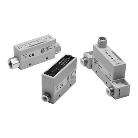
SMALL SIZE FLOW SENSOR
RAPIFLOW® FSM3 Series
・LCD display type
・Bar display type
・IO-Link type
INSTRUCTION MANUAL
SM-662466-A/6
取扱説明書
SM-358642
• Read this Instruction Manual before using the product.
• Especially, read the safety notes carefully.
• Keep this Instruction Manual in a safe and convenient place for future reference.
Advertisement
Table of Contents
Troubleshooting

Summary of Contents for SKD RAPIFLOW FSM3 Series
- Page 1 SMALL SIZE FLOW SENSOR RAPIFLOW® FSM3 Series ・LCD display type ・Bar display type ・IO-Link type INSTRUCTION MANUAL SM-662466-A/6 取扱説明書 SM-358642 • Read this Instruction Manual before using the product. • Especially, read the safety notes carefully. • Keep this Instruction Manual in a safe and convenient place for future reference.
-
Page 2: Preface
SM-662466-A/6 PREFACE PREFACE Thank you for purchasing CKD's "RAPIFLOW® FSM3 Series" compact size flow rate sensor. This Instruction Manual contains basic items such as installation and usage instructions in order to ensure optimal performance of the product. Please read this Instruction Manual thoroughly and use the product properly. -
Page 3: Safety Information
SM-662466-A/6 SAFETY INFORMATION SAFETY INFORMATION When designing and manufacturing a device using this product, the customer is responsible to manufacture a safe device. To achieve this, please verify the safety of electric control system is secured, which controls the mechanical mechanism of the device and, pneumatic pressure control circuit or water control circuit. -
Page 4: Precautions On Product Use
SM-662466-A/6 SAFETY INFORMATION Precautions on Product Use WARNING This product must be handled only by those who have enough knowledge and experience. This product was designed and manufactured as a general industrial machinery equipment and parts. This product must be used within its stated specifications. Do not use out of the specifications unique to this product. -
Page 5: Precautions Regarding Used Fluid
SM-662466-A/6 SAFETY INFORMATION CAUTION The flow rate is fluctuating, the measured flow rate value will also fluctuate. If the actual flow rate is fluctuating, the measured flow rate value will also fluctuate. Either increase the FSM3 display cycle or response time, or average the analog output on the device. - Page 6 SM-662466-A/6 SAFETY INFORMATION WARNING Do not use this product as a transaction meter. As it does not comply with Japanese Measurement Law and equivalent regulations of other countries, do not use for commercial transactions. Use the product only as the sensor for industry fields.
-
Page 7: Precautions Regarding Maintenance
SM-662466-A/6 SAFETY INFORMATION Precautions regarding maintenance CAUTION Do not use solvents, alcohol, and cleaning detergents to clean this product. The case is made of resin. The resin could absorb these chemicals. Wipe off dirt with a rag soaked in a diluted neutral detergent solution and wrung out well. Verify the flow rate accuracy periodically. -
Page 8: Table Of Contents
SM-662466-A/6 CONTENTS CONTENTS PREFACE ........................... i SAFETY INFORMATION ....................ii Precautions on Product Use ..................iii Precautions regarding used fluid ................... iv Precautions regarding maintenance ................vi CONTENTS ........................vii PRODUCT OVERVIEW ..................... 1 Model No. display ....................1 1.1.1 LDC display type (FSM3-L Series) .............. -
Page 9: Contents
SM-662466-A/6 CONTENTS 3.1.2 Explanation of functions ................79 3.1.3 How to operate .................... 82 3.1.4 How to key operate environment-resistant specifications......108 Use method of bar display type (FSM3-B series) .......... 109 3.2.1 Names of display section ................109 How to use the IO-Link type (FSM3-C series) ..........110 3.3.1 Names of display section ................ -
Page 10: Product Overview
BH Push-in (for φ 4 mm tube) G1/8 FSM3-L005U1BH1A1N-BMR-P80 CH Push-in (for φ 6 mm tube) G1/4 Model: RAPIFLOW FSM3 Series DH Push-in (for φ 8 mm tube) G1/2 [A] Display : Liquid crystal display Push-in (for φ 10 mm tube) - Page 11 SM-662466-A/6 1. PRODUCT OVERVIEW Compatibility table of flow rate range and port size, needle valve option, and EXA connection fitting [E] Port size [F] Piping direction :Port compatibility :Needle valve option compatibility :EXA connection fitting compatibility Compatibility table of port size and clean-room specifications [E] Port size [F] Piping direction Blank Blank...
- Page 12 1/4” JXR male fitting (50 L/min or less) 1/4” JXR male fitting (50 to 200 L/min) [F] Piping direction <Example of model No.> Straight FSM3-L005U2AA1A1N-BMR-P80 Model: RAPIFLOW FSM3 Series [G] Output specifications [A] Display : Liquid crystal display Analog output Switch output...
- Page 13 SM-662466-A/6 1. PRODUCT OVERVIEW Flow rate range and port size [E] Port size 1/4” Double 1/4” JXR barbed fitting Male fitting :Connection port compatibility :Needle valve option compatibility 2022-12-12...
- Page 14 (Voltage output) <Example of model No.> 1 point (PNP) 1-5 V FSM3-L005U4AA1A1N-BJR-P80-EX 2 points (PNP) ― 1 point (NPN) Model: RAPIFLOW FSM3 Series 1 point [A] Display : Liquid crystal display 2 points (NPN) ― (Current output) [B] Flow rate range...
- Page 15 SM-662466-A/6 1. PRODUCT OVERVIEW Flow rate range and port size 2022-12-12...
-
Page 16: Bar Display (Fsm3-B Series)
SM-662466-A/6 1. PRODUCT OVERVIEW 1.1.2 Bar display (FSM3-B series) ◼ Resin body type H S - P70 FSM3 - B 005 U 1 J 1 N BH 1 Code Content Model No. [A] Display [A] Display Bar display [B] Flow rate range (full scale flow rate) [B] Flow rate range 500 mL/min 50 L/min... - Page 17 SM-662466-A/6 1. PRODUCT OVERVIEW Compatibility table of flow rate range and port size, and EXA connection fitting [E] Port size [F] Piping direction :Port compatibility :EXA connection fitting compatibility Compatibility table of port size and clean-room specifications [E] Port size [F] Piping direction Blank Blank 2022-12-12...
- Page 18 1/4” double barbed fitting (50 to 200 L/min) <Example of model No.> 1/4” JXR male fitting (50 L/min or less) FSM3-B005U2AA1J1N-DHS-P70 1/4” JXR male fitting (50 to 200 L/min) Model: RAPIFLOW FSM3 Series [F] Piping direction [A] Display : Bar display [F] Piping direction...
- Page 19 SM-662466-A/6 1. PRODUCT OVERVIEW Flow rate range and port size [E] Port size 1/4” Double 1/4” JXR barbed fitting male fitting 2022-12-12...
- Page 20 Analog current output x 1 [H] Unit specifications <Example of model No.> [H] Unit specifications SI units only FSM3-B005U4AA1J1N-DJS-P70-EX [I] Valve option Model: RAPIFLOW FSM3 Series [I] Valve option None [A] Display : Bar display [B] Flow rate range : 500 mL/min...
- Page 21 SM-662466-A/6 1. PRODUCT OVERVIEW Flow rate range and port size 2022-12-12...
-
Page 22: Io-Link (Fsm3-C Series)
G1/2 *3 AA Rc1/8 NPT1/8 <Example of model No.> BA Rc1/4 NPT1/4 FSM3-C005U1BH1L1N-GHR-P70 CA Rc1/2 NPT1/2 Model: RAPIFLOW FSM3 Series [F] Piping direction [A] Display : IO-Link [F] Piping direction Straight [B] Flow rate range : 500 mL/min Elbow [C] Flow direction... - Page 23 SM-662466-A/6 1. PRODUCT OVERVIEW Flow rate range and port size [E] Port size [F] Piping direction :Port size compatibility Compatibility table of port size and clean-room specifications [E] Port size [F] Piping direction Blank Blank 2022-12-12...
- Page 24 <Example of model No.> 1/4” double barbed fitting (50 to 200 L/min) FSM3-C005U2AA1L1N-GHR-P70 1/4” JXR male fitting (50 L/min or less) Model: RAPIFLOW FSM3 Series 1/4” JXR male fitting (50 to 200 L/min) [A] Display : IO-Link [F] Piping direction...
- Page 25 SM-662466-A/6 1. PRODUCT OVERVIEW Flow rate range and port size [E] Port size 1/4” Double 1/4” JXR barbed fitting Male fitting 2022-12-12...
- Page 26 SM-662466-A/6 1. PRODUCT OVERVIEW 1.1.4 Option Code Content [A] Option FSM3 - K - P70 5-conductor cable 1 m (for LCD display) 5-conductor cable 3 m (for LCD display) 4-conductor cable 1 m (for bar display) [B] Clean-room specifications 4-conductor cable 3 m (for bar display) [A] Option M12 both ends connector cable (3 m) (for IO-Link) Bracket 1 (for models with a flow rate range below...
-
Page 27: Specifications
SM-662466-A/6 1. PRODUCT OVERVIEW 1.2 Specifications 1.2.1 LCD display type ◼ Resin body type FSM3-[A][B][C][D][E][F][G][H][I] - [ Item Uni-direction Flow direction [C] Bi-direction 15 to 500 30 to 1000 0.06 to 0.15 to 0.30 to 0.6 to 20.0 1.5 to 50.0 3.0 to 15 to 500 30 to... - Page 28 SM-662466-A/6 1. PRODUCT OVERVIEW The value converted to volumetric flow rate at standard condition (20°C 1 barometric pressure (101 kPa) relative humidity 65%). (For gas other than air, 20°C 1 barometric pressure (101 kPa), relative humidity 0%) The displays of each flow rate are as shown below. Measured flow rate range “Lo”...
- Page 29 SM-662466-A/6 1. PRODUCT OVERVIEW ◼ Stainless steel body type FSM3-[A][B][C][D][E][F][G][H][I]-[ Item Uni-direction Flow direction [C] Bi-direction 15 to 30 to 1000 0.06 to 0.15 to 0.30 to 0.60 to 1.5 to 50.0 3.0 to 30 to 1000 6 to 200 L 15 to 500 L 500 mL 2.00 L 5.00 L...
- Page 30 SM-662466-A/6 1. PRODUCT OVERVIEW The value converted to volumetric flow rate at standard condition (20°C 1 barometric pressure (101 kPa) relative humidity 65%). (For gas other than air, 20°C 1 barometric pressure (101 kPa), relative humidity 0%) The displays of each flow rate are as shown below. Measured flow rate range “Lo”...
- Page 31 SM-662466-A/6 1. PRODUCT OVERVIEW ◼ Environment-resistant specifications FSM3-[A][B][C][D][E][F][G][H][I]-[ Item Uni-direction Flow direction [C] Bi-direction 15 to 30 to 1000 0.06 to 0.15 to 0.30 to 0.60 to 1.5 to 50.0 3.0 to 30 to 1000 6 to 200 L 15 to 500 L 500 mL 2.00 L 5.00 L...
- Page 32 SM-662466-A/6 1. PRODUCT OVERVIEW The value converted to volumetric flow rate at standard condition (20°C 1 barometric pressure (101 kPa) relative humidity 65%). (For gas other than air, 20°C 1 barometric pressure (101 kPa), relative humidity 0%) The displays of each flow rate are as shown below. Measured flow rate range “Lo”...
-
Page 33: Bar Display Type
SM-662466-A/6 1. PRODUCT OVERVIEW 1.2.2 Bar display type ◼ Resin body type FSM3-[A][B][C][D][E][F][G][H][I]-[ Item Uni-direction Flow direction [C] Bi-direction 15 to 500 30 to 1000 0.06 to 0.15 to 0.30 to 10.00 0.60 to 1.5 to 3.0 to 6 to 200 15 to 500 30 to 1000 Measured... - Page 34 SM-662466-A/6 1. PRODUCT OVERVIEW The value converted to volumetric flow rate at standard condition (20 °C 1 barometric pressure (101 kPa) relative humidity 65%). (For gas other than air, 20 °C 1 barometric pressure (101 kPa), relative humidity 0%) Use dry gas which does not contain corrosive elements such as chlorine, sulfur or acids, and clean which does not contain dust or oil mist.
- Page 35 SM-662466-A/6 1. PRODUCT OVERVIEW ◼ Stainless steel body type FSM3-[A][B][C][D][E][F][G][H][I]-[ Item Uni-direction Flow direction [C] Bi-direction 15 to 500 30 to 1000 0.06 to 0.15 to 0.30 0.60 to 1.5 to 50.0 3.0 to 30 to 1000 6 to 200 L 15 to 500 L 2.00 L 5.00 L 10.00 L...
- Page 36 SM-662466-A/6 1. PRODUCT OVERVIEW The value converted to volumetric flow rate at standard condition (20°C 1 barometric pressure (101 kPa) relative humidity 65%). (For gas other than air, 20°C 1 barometric pressure (101 kPa), relative humidity 0%) Use dry gas which does not contain corrosive elements such as chlorine, sulfur or acids, and clean gas which does not contain dust or oil mist.
- Page 37 SM-662466-A/6 1. PRODUCT OVERVIEW ◼ Environment-resistant specifications FSM3-[A][B][C][D][E][F][G][H][I]-[ Item Uni-direction Flow direction [C] Bi-direction 15 to 500 30 to 1000 0.06 to 0.15 to 0.30 0.60 to 1.5 to 50.0 3.0 to 30 to 1000 6 to 200 L 15 to 500 L 2.00 L 5.00 L 10.00 L...
- Page 38 SM-662466-A/6 1. PRODUCT OVERVIEW The value converted to volumetric flow rate at standard condition (20°C 1 barometric pressure (101 kPa) relative humidity 65%). (For gas other than air, 20°C 1 barometric pressure (101 kPa), relative humidity 0%) Use dry gas which does not contain corrosive elements such as chlorine, sulfur or acids, and clean gas which does not contain dust or oil mist.
-
Page 39: Io-Link Type
SM-662466-A/6 1. PRODUCT OVERVIEW 1.2.3 IO-Link type ◼ Resin body type FSM3-[A][B][C][D][E][F][G][H][I]-[ Item Uni-direction Flow direction [C] Bi-direction 15 to 500 30 to 1000 0.06 to 0.15 to 0.30 to 0.60 to 1.5 to 50.0 3.0 to 30 to 1000 Measured 6 to 200 L 15 to 500 L 2.00 L... - Page 40 SM-662466-A/6 1. PRODUCT OVERVIEW The value converted to volumetric flow rate at standard condition (20 °C 1 barometric pressure (101 kPa) relative humidity 65%). (For gas other than air, 20 °C 1 barometric pressure (101 kPa), relative humidity 0%) Use dry gas which does not contain corrosive elements such as chlorine, sulfur or acids, and clean gas which does not contain dust or oil mist.
- Page 41 SM-662466-A/6 1. PRODUCT OVERVIEW ◼ Stainless steel body type FSM3-[A][B][C][D][E][F][G][H][I]-[ Item Uni-direction Flow direction Bi-direction 15 to 30 to 1000 0.06 to 0.15 to 0.30 to 0.60 to 1.5 to 50.0 3.0 to 30 to 1000 Measured 6 to 200 L 15 to 500 L 500 mL 2.00 L 5.00 L...
- Page 42 SM-662466-A/6 1. PRODUCT OVERVIEW The value converted to volumetric flow rate at standard condition (20°C 1 barometric pressure (101 kPa) relative humidity 65%RH). (For gas other than air, 20°C 1 barometric pressure (101 kPa), relative humidity 0%RH) Use dry gas which does not contain corrosive elements such as chlorine, sulfur or acids, and clean gas which does not contain dust or oil mist.
-
Page 43: Communication Specification
SM-662466-A/6 1. PRODUCT OVERVIEW 1.3 Communication specification 1.3.1 General Item Details Item Details Communication protocol IO-Link Min. Cycle Times 5 ms Communication protocol revision V1.1 Data Storage 1 kbyte Transmission speed COM2 (38.4 kbps) SIO Mode support Port type Class A Device ID Refer to the table below. -
Page 44: On Demand Data
SM-662466-A/6 1. PRODUCT OVERVIEW 1.3.2 On demand data ◼ Identification Vendor ID: 855 (Decimal number) / 357 (Hexadecimal number) Index Sub Index Item Value Access Data length Format 0x0010 Vendor Name CKD Corporation 64 bytes String 0x0011 Vendor Text https://www.ckd.co.jp/ 64 bytes String 0x0012... - Page 45 SM-662466-A/6 1. PRODUCT OVERVIEW ◼ Flow rate range for each model Instantaneous flow rate Integration flow rate Model No. Decimal Decimal Integration Display range Output value point Output value point display range position position FSM3-C005U -50 to 550 mL/min -50 to 550 to 9999999 mL to 9999999 FSM3-C010U...
-
Page 46: Parameter And Commands
SM-662466-A/6 1. PRODUCT OVERVIEW 1.3.3 Parameter and commands ◼ Common specification Data Index Item Value Access Format Index length Refer to “Table 1” shown 0x0002 System Command 1 byte UInteger8 below. 0x0000: No lock 0x000C Device Access Locks 0x0001: parameter lock 2 bytes Record 0x0002: Date storage lock... - Page 47 SM-662466-A/6 1. PRODUCT OVERVIEW ◼ Individual specification Data Index Sub Index Item Value Access Format length 1: AIR / 2: AR / 0x0100 Gas type 3: CO / 7: MAG(8:2) / 2 bytes Integer16 〇 10: O 0x0101 Flow direction 0: Uni-direction / 2: Bi-direction 2 bytes Integer16...
-
Page 48: Process Data In
SM-662466-A/6 1. PRODUCT OVERVIEW 1.3.4 Process data IN Date name Instantaneous flow rate <Flow Rate> Data range Refer to the instantaneous flow rate output value in “1.3.2 On demand data”. Format Integer16 Switch ― ― ― ― ― ― ― ―... -
Page 49: Diagnosis
SM-662466-A/6 1. PRODUCT OVERVIEW 1.3.6 Diagnosis Event Device Type Contents Measures code status 0x4210 Warning Out of Temperature of IO-Link driver is high Check the connection. specification 0x5111 Warning Out of Supply voltage drop Check the power supply voltage. specification (Approx. -
Page 50: Dimensions
SM-662466-A/6 1. PRODUCT OVERVIEW 1.4 Dimensions 1.4.1 LDC display type ◼ Resin body type Port size: Straight type φ 4 mm, φ 6 mm, φ1/4”, Rc1/8, G1/8, NPT1/8 ●FSM3 – L[B][C]1/BH1/CH1/HH1/AA1/AF1/AB1/AC1 (Full scale flow rate: 500 mL/min, 1,2,5,10,20,50 L/min) G screw shape (AB) End surface The 15°... - Page 51 SM-662466-A/6 1. PRODUCT OVERVIEW Port size: Straight Rc1/2, G1/2, NPT1/2 ●FSM3 – L[B][C]1/CA1/CF1/CB1/CC1 (Full scale flow rate: 500, 1000 L/min) G screw shape (CB) End surface The 15° surface is the seal surface. Note that it is not the end surface seal. Also, be sure to confirm that the screw depth of the fitting matches before use.
- Page 52 SM-662466-A/6 1. PRODUCT OVERVIEW Dimensions with needle valve Connection diameter: φ 4 mm, φ 6 mm, φ 1/4”, Rc1/8, G1/8, NPT1/8 ●FSM3 – L[B][C]1/BH1/CH1/HH1/AA1/AF1/AB1/AC1/[G][H]T (Full scale flow rate: 500 mL/min,1,2,5,10,20,50 L/min) G screw shape (AB) *The shape of upper surface and bottom surface of the main body is identical with the straight type.
- Page 53 SM-662466-A/6 1. PRODUCT OVERVIEW ◼ Stainless steel body type Connection diameter: Straight type Rc1/8, G1/8, NPT1/8 Connection diameter: Straight type G1/8 L ሾ B ሿ ሾCሿ /AA1/AB1/AC1 L ሾ B ሿ ሾCሿ /AF1 ●FSM3 ●FSM3 – – (Full scale flow rate: 500 mL/min,1,2,5,10,20,50 L/min) G screw shape (AB) Connection diameter: Straight type G1/8 (AF1) End surface...
- Page 54 SM-662466-A/6 1. PRODUCT OVERVIEW Connection diameter: Straight Rc 1/4, G1/4, NPT1/4 Connection diameter: Straight G1/4 (BF1) L ሾ B ሿ ሾCሿ / BA1/BB1/BC1 ●FSM3 L ሾ B ሿ ሾCሿ / BF1 – ●FSM3 – (Full scale flow rate: 50,100,200 L/min) (Full scale flow rate: 50,100,200 L/min) Connection diameter: Straight type G1/4 (BF1) G screw shape (BB)
- Page 55 SM-662466-A/6 1. PRODUCT OVERVIEW Connection diameter: Straight type Rc1/2, G1/2, NPT1/2 L[B][C]2/CA1/CF1/CB1/CC1 ●FSM3 – (Full scale flow rate: 500,1000 L/min) G screw shape (CB) End surface The 15° surface is the seal surface. Note that it is not the end surface seal. Also, be 2-M3 depth 3 sure to confirm that the screw depth of the fitting matches before use.
- Page 56 SM-662466-A/6 1. PRODUCT OVERVIEW ◼ Environment-resistant specifications 2022-12-12...
-
Page 57: Bar Display Type
SM-662466-A/6 1. PRODUCT OVERVIEW 1.4.2 Bar display type ◼ Resin body type Connection diameter: Straight type φ 4 mm, φ 6 mm, φ 1/4”, Rc1/8, G1/8, NPT1/8 ●FSM3 – B[B][C]1/BH1/CH1/HH1/AA1/AF1/AB1/AC1 (Full scale flow rate: 500 mL/min,1,2,5,10,20,50 L/min) Rc 1/8,NPT1/8,G1/8(AB1) G screw shape (AB) End surface The 15°... - Page 58 SM-662466-A/6 1. PRODUCT OVERVIEW Connection diameter: Straight type Rc1/2, G1/2, NPT1/2 ●FSM3 – B[B][C]1/CA1/CF1/CB1/CC1 (Full scale flow rate: 500,1000 L/min) G screw shape (CB) The 15° surface is the seal surface. Note that it is not the end surface seal. Also, be sure to confirm that the screw depth of the fitting End surface matches before use.
- Page 59 SM-662466-A/6 1. PRODUCT OVERVIEW ◼ Stainless steel body type Connection diameter: Straight type Rc1/8, G1/8, NPT1/8 ●FSM3 – B ሾ B ሿ ሾCሿ / AA1/AB1/AC1 (Full scale flow rate: 500 mL/min,1,2,5,10,20,50 L/min) G screw shape (AB) 2-φ3.4 penetration End surface The 15°...
- Page 60 SM-662466-A/6 1. PRODUCT OVERVIEW Connection diameter: Straight G1/4 Connection diameter: Straight type Rc1/4, G1/4, NPT1/4 ●FSM3 B ሾ B ሿ ሾCሿ / BF1 – B ሾ B ሿ ሾCሿ / BA1/BB1/BC1 ●FSM3 – (Full scale flow rate: 50,100,200 L/min) (Full scale flow rate: 50,100,200 L/min) G screw shape (BB) 2-φ3.4 penetration 2-φ3.4 penetration...
- Page 61 SM-662466-A/6 1. PRODUCT OVERVIEW ◼ Environment-resistant specifications 2022-12-12...
-
Page 62: Io-Link Type
SM-662466-A/6 1. PRODUCT OVERVIEW 1.4.3 IO-Link type ◼ Resin body type Connection diameter: Straight type φ 4 mm, φ 6 mm, φ 1/4”, Rc1/8, G1/8, NPT1/8 ●FSM3 – C[B][C]1/BH1/CH1/HH1/AA1/AF1/AB1/AC1 (Full scale flow rate: 500 mL/min, 1,2,5,10,20,50 L/min) G screw shape (AB) M12 connector, 4-pin End surface The 15°... - Page 63 SM-662466-A/6 1. PRODUCT OVERVIEW Connection diameter: Straight type Rc1/2, G1/2, NPT1/2 ●FSM3 – C[B][C]1/CA1/CF1/CB1/CC1 (Full scale flow rate: 500,1000 L/min) G screw shape (CB) The 15° surface is the seal surface. Note that it is not the end surface seal. Also, be sure to confirm that the screw depth of the fitting matches before use.
- Page 64 SM-662466-A/6 1. PRODUCT OVERVIEW ◼ Stainless steel body type Connection diameter: Straight type Rc1/8, G1/8, NPT1/8 ●FSM3 – C ሾ B ሿ ሾCሿ / AA1/AB1/AC1 (Full scale flow rate: 500 L/min, 1,2,5,10,20,50 L/min) G screw shape (AB) M12 connector, 4-pin 2-φ3.4 penetration End surface The 15°...
- Page 65 SM-662466-A/6 1. PRODUCT OVERVIEW Connection diameter: Straight type G1/4 Connection diameter: Straight type Rc1/4, G1/4, NPT1/4 ●FSM3 – C ሾ B ሿ ሾCሿ /CF1 ●FSM3 – C ሾ B ሿ ሾCሿ /BA1/BB1/BC1 (Full scale flow rate: 50,100,200 L/min) (Full scale flow rate: 50,100,200 L/min) G screw shape (BB) 2-φ3.4 penetration 2-φ3.4 penetration...
- Page 66 SM-662466-A/6 1. PRODUCT OVERVIEW 1.4.4 Option ●FSM3-A,B ●FSM3-C,D 5-conductor lead wire 4-conductor lead wire (For Bar indicator type) (For LCD indicator type, Separated indicator type) 30 or less Connector cover 30 or less Connector cover Material: EPDM Material: EPDM Half strip Half strip Contact: J.S.T Mfg.
- Page 67 SM-662466-A/6 1. PRODUCT OVERVIEW ●FSM3-H ●FSM3-J Bracket 1 (For 200 L or less model) Bracket 2 (For 500 L and 1000 L models) Model No. Dimensions (A) FSM3-1/BH1/CH1/HH1/AA1/AF1/AB1/AC1/AD1/AE1 13.5 FSM3-1/DH1/EH1/JH1/BA1/BF1/BB1/BC1/BD1/BE1 18.0 ●FSM3-K Panel mounting kit 1 (For LCD indicator type, Separated indicator type) [Panel cut dimensions] Single mount ...
-
Page 68: Products Weight
SM-662466-A/6 1. PRODUCT OVERVIEW 1.4.5 Products weight ◼ Resin body type [Unit: g] Fitting LCD indicator type Bar display IO-Link type No needle With needle type Model Content valve valve Push-in (φ 4 mm straight) Push-in (φ 6 mm straight) Push-in (φ... - Page 69 SM-662466-A/6 1. PRODUCT OVERVIEW ◼ Environment-resistant specifications 2022-12-12...
-
Page 70: Option (Atex Compliant)
SM-662466-A/6 1. PRODUCT OVERVIEW 1.5 Option (ATEX Compliant) WARNING Attach the product to grounded metal. Wipe it with a damp cloth. There is a possibility that the electrostatic charge could be drained. In an explosive atmosphere, never unplug and plug back in this product while it is being energized. -
Page 71: Installation
SM-662466-A/6 2. INSTALLATION 2. INSTALLATION 2.1 Installation Environment WARNING Do not use in a corrosive gas atmosphere such as sulfurous acid gas. This product shall be used in the ambient temperature 0 to 50°C. Even within the temperature range, do not use in places where temperature changes suddenly causing dew condensation. - Page 72 SM-662466-A/6 2. INSTALLATION CAUTION Do not turn the elbow fitting or screw-in fitting more than necessary. Elbow fitting or screw-in fitting of resin body type can be rotated about 10 times, but do not rotated the fitting except when changing the orientation during installation. If it is rotated more than necessary the seal parts may get caught or worn, causing external leakage.
-
Page 73: Mounting Method
SM-662466-A/6 2. INSTALLATION 2.2 Mounting Method ・It may be difficult to view the LCD, depending on the angle. ・This product can be installed with any direction; vertical, horizonal, left, and right orientation. ・The tightening torque for screws should be 0.5 N・m. Lateral mounting Vertical mounting (use of through hole) - Page 74 SM-662466-A/6 2. INSTALLATION Panel mounting (non-needle valve) FSM3 - *005 to 201 (non-needle valve) Single item model No.: FSM3-K Panel mounting (with needle valve) FSM3 - *005 to 201 (with needle valve) Single item model No.: FSM3-L The panel vessel is inserted from the The panel vessel is inserted from the Insert the sensor from the back side front side of the panel.
-
Page 75: Piping Method
SM-662466-A/6 2. INSTALLATION 2.3 Piping Method 2.3.1 Cleaning the pipes Before installing piping, clean out the pipes using air blower to remove all foreign objects and cutting chips from the pipes. The rectifier or platinum sensor could be damaged if foreign objects, cutting chips, etc., enter the pipes. -
Page 76: Tightening
SM-662466-A/6 2. INSTALLATION 2.3.4 Tightening • When mounting on piping, do not apply excessive screwing, torque and load torque on the connection board. Also, use a wrench on the metallic part of the body at piping to avoid force on the resin part. •... -
Page 77: Exa Connection Method
SM-662466-A/6 2. INSTALLATION 2.3.5 EXA connection method To connect the EXA-02-□2C-□ (sold separately) and the EXA connection fitting type of FSM3, remove the fitting fixation pin on IN side of EXA, and after inserting the dedicated connection fitting of OUT side of FSM3 to the end, fix with the fitting fixation pin firmly again. -
Page 78: Wiring Method
SM-662466-A/6 2. INSTALLATION 2.4 Wiring method DANGER Do not use by exceeding the power supply voltage range. If voltage exceeding the power supply voltage range indicated in the specification is applied, it may cause malfunction, damage of this product, electric shock and fire. Do not connect the load exceeding the output ratings. - Page 79 SM-662466-A/6 2. INSTALLATION WARNING Use the impedance of connection load after verification. The output impedance of the analog output voltage output type is approx. 1 kΩ. If the impedance of the connecting load is low, the output error increases. Check for an error with the impedance of the connecting load before using.
-
Page 80: Ldc Display (Npn Output)
SM-662466-A/6 2. INSTALLATION 2.4.1 LDC display (NPN output) ◼ FSM3-L*****B/F (One analog, 2 switches) (Brown) Power supply + 1 Load (Black) CH1 SW output 1 Load Using CH2 as switch output (White) CH2 SW output 2 (Gray) Analog output Load (Blue) Power supply - (Brown) Power supply + Load... -
Page 81: Ldc Display Type (Pnp Output)
SM-662466-A/6 2. INSTALLATION 2.4.2 LDC display type (PNP output) ◼ FSM3-FSM3-L*****D/H (One analog, 2 switches) (Brown) Power supply + (Black) CH1 SW output 1 Using CH2 as (White) CH2 Load SW output 2 switch output Load (Gray) Analog output (Blue) Load Power supply (Brown) Power supply +... -
Page 82: Copying Setting Values
SM-662466-A/6 2. INSTALLATION 2.4.3 Copying setting values ◼ FSM3-L*****A/C/E/G/** (LCD indicator type, with copy function) Power supply + Power supply + SW output 1 SW output 1 Copy terminal Copy terminal Setting copy Analog output Analog output Power supply - Power supply - FSM3 (slave) FSM3 (master) -
Page 83: Connection Between Bar Display Type And Separate Display Device
SM-662466-A/6 2. INSTALLATION 2.4.5 Connection between Bar display type and separate display device E-con Sumitomo 3M Wire mount plug (Brown) Power supply + Separate display device FSM3 (Black) Sensor LED Bar indicator type Voltage output type (White) Model identifying signal (The current output type cannot be (Blue) Power supply - connected) -
Page 84: Analog Output Characteristics
SM-662466-A/6 2. INSTALLATION 2.5 Analog output characteristics Flow direction Voltage output type Current output type [Bi- direction] (mA) 100% 100% -100% -100% Flow rate Flow rate Flow rate Flow rate Flow rate (L/min) Flow rate (L/min) [Uni-direction] (mA) 100% 100% Flow rate Flow rate Flow rate (L/min) -
Page 85: Usage
SM-662466-A/6 3. USAGE 3. USAGE WARNING When using, perform warming-up (five minutes or more after electrification). Output accuracy is influenced by self-heating with electrification in addition to temperature characteristics. When changing the setting values, change after stopping the equipment. The control device may conduct unexpected operations. Do not disassemble and modify this product. - Page 86 SM-662466-A/6 3. USAGE CAUTION When using the LCD display, do not press down on the display section. This may lead to failure. This product uses a micro-sensor chip, and must be installed where it will not be subject to dropping, impact or vibration. Handle this product as a precision component during installation and transportation.
- Page 87 SM-662466-A/6 3. USAGE CAUTION Do not turn the fitting while applying fluid pressure on this product. It may cause external leakage. Also, do not turn the fitting while using this product. Install the protective cover correctly. The explosion-proof and protective structures function with the protective cover (transparent cover) correctly attached.
-
Page 88: How To Use The Lcd Display (Fsm3-L Series)
SM-662466-A/6 3. USAGE 3.1 How to use the LCD display (FSM3-L series) 3.1.1 Names and functions of display/operation section Main display section (green/red) Output (OUT1) display (green) ・Displays flow rate and setting values. Flow rate unit display ・Turns on when CH1 output is ON. ・The display color can be switched with settings. - Page 89 SM-662466-A/6 3. USAGE ◼ SET mode Item Description Factory setting Selection of CH1 Select the function of CH1. F.01 No switch output operation You can set switch output operation and set the integrated pulse. Select the function of CH2. Selection of CH2 F.02 Select if CH2 is used as switch output or external input (integrated No switch output...
- Page 90 SM-662466-A/6 3. USAGE ◼ Maintenance mode Item Description Factory setting Forced output Use this function to forcibly turn the switch output ON and confirm F.91 - function the wiring connection and initial operation of the input device. Adjusted value: Zero adjustment F.92 The zero point deviation is corrected (Range: Within ±10%F.S.) function...
-
Page 91: How To Operate
SM-662466-A/6 3. USAGE 3.1.3 How to operate ◼ Normal operation (RUN mode) * When no instruction is provided on how to press a key, it means to press the key once. <RUN display screen> If the key pressed once in the RUN display screen, the user enters to the change screen of RUN mode. Press the key to switch the mode, and key to confirm. - Page 92 SM-662466-A/6 3. USAGE ● Instantaneous flow rate display While pushing and holding for one Instantaneous flow rate display CH1 data display second or more CH1 lower limit set value display CH1 upper limit set value display <Sub: Flow direction> Alternate <Sub: Reference state>...
- Page 93 SM-662466-A/6 3. USAGE CH1 and CH2 data display <At Window operation (1) setting> Upper limit set value Lower limit set value Alternate <At integrated output (1) setting> Integrated set value Alternate <At integrated pulse setting> <At integrated clear setting> (CH2 only) <At auto-reference external input setting>...
- Page 94 SM-662466-A/6 3. USAGE ● Peak hold function Able to know the maximum value and minimum value indicated by the flow rate value. There are the measurement/stop states, and values are acquired at the measurement state. Also, press the 1 button to switch to the instantaneous flow rate display. Instantaneous flow rate display Peak bottom display (Simple)
- Page 95 SM-662466-A/6 3. USAGE ● CO discharge amount display The compressor’s power consumption is calculated from the integrated flow rate value, and calculate discharge amount by multiplying the discharge coefficient of electricity. By setting the compressor capacity (power, discharge pressure and discharge flow rate) and CO conversion coefficient with "F.15: CO discharge amount calculation setting"...
- Page 96 SM-662466-A/6 3. USAGE ● Integrated flow rate display Press and hold for one second Start integration Integrated flow rate display <Measuring> Press and hold for one second Stop integration <Stopping> Reset 1 second 3 seconds 5 seconds or more or more or more To <SET mode>...
- Page 97 SM-662466-A/6 3. USAGE ◼ SET mode When pressing and holding the key for 2 seconds (keep pressing) in the RUN display state, < RUN display screen > the user enters to the SET mode. Press the key to switch the mode, and press the key to confirm.
- Page 98 SM-662466-A/6 3. USAGE ● F.01: CH1 Operation setting Select a function of CH1. Able to set the switch output operation and integrated pulse. <Setting selection screen> Not used Press and Press and Press and hold for one hold for one hold for one second second...
- Page 99 SM-662466-A/6 3. USAGE ● F.02: CH2 operation setting Selects a function of CH2. Select/set if CH2 is used as the switch output or external input (integrated value reset and auto-reference). When settings are done with "F.06: Flow direction setting", "F.08: Reference state setting", <Setting selection screen>...
- Page 100 SM-662466-A/6 3. USAGE Supplement [1]: Switch output function Depending on the application, you can choose from 8 types of switch operation. Operation pattern LCD display Description Operation waveform name (Sub-display) Switch operation OFF Switch operation is the OFF state. Flow rate Window operation (1) The switch output turns (Inside range ON)
- Page 101 SM-662466-A/6 3. USAGE Supplement (2): Auto-reference function The auto-reference function loads the measuring flow rate and make it a threshold value of the switch output. Loading is done with a button operation or the external input of CH2, and it is outputs from CH1. When a workpiece changes and the threshold value of the switch changes, a threshold value can be changed automatically.
- Page 102 SM-662466-A/6 3. USAGE Auto-reference function No. of Operation input Description Operation waveform LCD display pattern name points Loaded value or Turn the loaded value or above above ON (Threshold: Loaded value) Loaded value Flow rate 1 point (1-P) Input value or Turn the loaded value or above above OFF OFF.
- Page 103 SM-662466-A/6 3. USAGE ● F.03: Integration setting The user can select whether to acquire an integrated flow rate value consecutively or perform time setting. Also, the user can select to save an integrated flow rate value. Measurement method setting Data saving setting Consecutive Do not save Return to SET...
- Page 104 SM-662466-A/6 3. USAGE ● F.06: Flow direction setting (Bi-direction type only. Uni-direction type is not displayed.) Select the flow direction. Bi-direction, uni-direction, and uni-reverse direction can be selected. Forward direction Bi-direction Reverse direction Return to SET mode selection screen ・When a flow direction is set, the setting values below are cleared. Always set a flow direction first. ・Switch setting ・Peak bottom value ・Integrated flow rate value...
- Page 105 SM-662466-A/6 3. USAGE ● F.07: Display reverse setting The top and bottom of LCD display can be reversed. Reversed Standard Return to SET mode selection screen ・Even when the display is reversed, the key operation remains the same. If operation is performed with the key in the standard display, it is also performed with the key in the reverse display.
- Page 106 SM-662466-A/6 3. USAGE ● F.09: Unit setting (For overseas model only – Unit specification “2”) The unit can be set from “L/min” and “cf/h”. (For 1000 L/min type, “cf/min” can be set instead of “cf/h”) L/min cf/h cf/min Return to SET mode selection screen ・When a unit is set, the setting values below are cleared.
- Page 107 SM-662466-A/6 3. USAGE ● F.10: Display cycle setting The display cycle of the digital display can be changed in 3 levels from 0.25 s to 1 s. If the display flicks, it can be improved by setting the long display update cycle. 0.25sec 0.5sec 1sec...
- Page 108 SM-662466-A/6 3. USAGE ● F.13: Gas type switch function Able to switch a gas type to measure. This function can be used with the flow rate range: 500 mL/min to 200 L/min type. Oxygen type has no gas type switching. Return to SET mode selection screen...
- Page 109 SM-662466-A/6 3. USAGE ● F.15: CO discharge amount calculation setting Perform settings to calculate the CO discharge amount. The input values are the compressor’s power, discharge pressure, discharge flow rate, and conversion coefficient (kg (CO )/kWh). Set the compressor’s power, discharge pressure, discharge flow rate, and CO conversion coefficient of the compressor being used.
- Page 110 SM-662466-A/6 3. USAGE ● F.16: Lock setting This setting is for the lock. Error operation can be prevented by making key operation invalid. There are two types of lock method to select: Key lock method and PIN number method, and each has different releasing method.
- Page 111 SM-662466-A/6 3. USAGE ● F.17: Peak hold setting Able to select to acquire peak hold values consecutively or specify time. Also, it can be selected if the peak hold value should be saved. Data saving setting Measurement method setting Continuous Not saved Return to SET Press and...
- Page 112 SM-662466-A/6 3. USAGE ◼ Maintenance mode <RUN display screen> Press and Press and hold for 5 hold for 2 seconds seconds <Function selection screen> While pressing Forced output for one second or more While pressing for one second or more While pressing for one second or more Zero adjust execution...
- Page 113 SM-662466-A/6 3. USAGE ● F.91: Forced output function The switch output is forced to turn ON, and used for wiring connections and initial operation verification of input devices. While pressing and holding for one second or more <CH1 output> While pressing and holding for one second or more <CH2 output>...
- Page 114 SM-662466-A/6 3. USAGE ● F.93: Copy function Between two FSM3s, operations and setting values can be easily copied. (Copying is possible between the products of the identical model number) Waiting to send After Sending success Sending side <Copy function> 5 seconds Waiting to receive Receiving side Receiving success...
- Page 115 SM-662466-A/6 3. USAGE ◼ Setting monitor mode < RUN display screen > In the instantaneous flow rate display state, if you press and hold key for 3 seconds (keep pressing), it enters into the setting monitor mode. Press the key to enter the selection screen, switch to the function you want to check with key, press the key and check the contents.
- Page 116 SM-662466-A/6 3. USAGE ● Model display A model (the current setting state) can be confirmed. It shows in the order of “Zero adjust value”, “Flow rate amount range + gas type”, “Flow rate reference + flow direction” and “Output specification + No. of output points”. Flow rate range + Flow rate reference Output specification +...
-
Page 117: How To Key Operate Environment-Resistant Specifications
SM-662466-A/6 3. USAGE 3.1.4 How to key operate environment-resistant specifications Environment-resistant specifications can be key operated by opening the protective cover. Loosen the two cover bolts and open the protective cover as shown in the figure below. Protective cover Cover bolts Specified torque: 0.6N・m±10% Excluding key operating, use this product with the protective cover is closed and the cover bolts are tighten and fixed with the specified torque. -
Page 118: Use Method Of Bar Display Type (Fsm3-B Series)
SM-662466-A/6 3. USAGE 3.2 Use method of bar display type (FSM3-B series) 3.2.1 Names of display section Flow rate bar display ・It turns ON according to the flow rate. ・It flashes at overflow rate. <Display example> The display is in case of FSM3-B101□□□□□□□. Flow rate Uni-direction type Bi-direction type... -
Page 119: How To Use The Io-Link Type (Fsm3-C Series)
SM-662466-A/6 3. USAGE 3.3 How to use the IO-Link type (FSM3-C series) 3.3.1 Names of display section Power lamp (green) ・Lights when power supply is ON. ・Blinks during IO-Link communication. Status lamp (Green, Orange, Red) Turns OFF when the flow rate is within ±3%. ・OFF…... -
Page 120: Flow Rate Logic Calculation Method
SM-662466-A/6 3. USAGE 3.4 Flow rate logic calculation method Use for flow rate range selection estimate when using a flow rate sensor for attaching/detaching of suction nozzle. A flow rate can ⚫ Calculating flow rate from the effective be calculated from the pressure difference and inside/outside of the effective sectional area of nozzle (pinhole). -
Page 121: Troubleshooting
SM-662466-A/6 4. TROUBLESHOOTING 4. TROUBLESHOOTING 4.1 Error code (LCD display type) Error code Cause Countermeasures The flow rate exceeds the Reduce the instantaneous flow rate value to flow rate display range. within the flow rate range. Check that the flow rate is within the flow range and turn the power supply ON again. - Page 122 SM-662466-A/6 4. TROUBLESHOOTING Error code Cause Countermeasures Button operations Release the lock before operation. locked. Enter the set PIN number. * Be careful not to forget your PIN number. A pin number is set. If you have forgotten your PIN code, please contact your nearest CKD sales office.
-
Page 123: Error Code (Bar Display Type)
SM-662466-A/6 4. TROUBLESHOOTING 4.2 Error code (Bar display type) Error code Cause Countermeasures The third from left blinks error occurred Turn the power supply ON again. during memory reading If it still does not return to normal, the product or writing. may be faulty. -
Page 124: Troubleshooting
SM-662466-A/6 4. TROUBLESHOOTING 4.4 Troubleshooting Trouble Cause Corrective action Wrong connection of power source. Connect the rated power supply correctly. Please press either the MODE key or the + key or - key to confirm that it will light again. (Do not push the button for a It is in eco-mode. - Page 125 SM-662466-A/6 4. TROUBLESHOOTING Trouble Cause Corrective action Fluid leakage Check piping for leakage. Foreign objects are in the main body and correct flow rate Foreign objects are mixed inside the cannot be viewed correctly. Replace FSM3. main body. When installing the main body, make sure that there is no (Foreign objects sticking to sensor foreign object in the piping or the port of the main unit, and use chip.)
- Page 126 SM-662466-A/6 4. TROUBLESHOOTING Trouble Cause Corrective action Foreign objects are mixed inside the main body and it is not Foreign objects are mixed inside the possible to measure the correct flow rate. Please replace main body. FSM3. When installing the main body, make sure that there is (Foreign objects sticking to sensor no foreign object in the piping or the port of the main body, and chip.)
-
Page 127: Warranty Provisions
SM-662466-A/6 5. WARRANTY PROVISIONS 5. WARRANTY PROVISIONS 5.1 Warranty conditions ◼ Warranty coverage If the product specified herein fails for reasons attributable to CKD within the warranty period specified below, CKD will promptly provide a replacement for the faulty product or a part thereof or repair the faulty product at one of CKD’s facilities free of charge.
Need help?
Do you have a question about the RAPIFLOW FSM3 Series and is the answer not in the manual?
Questions and answers