Advertisement
Quick Links
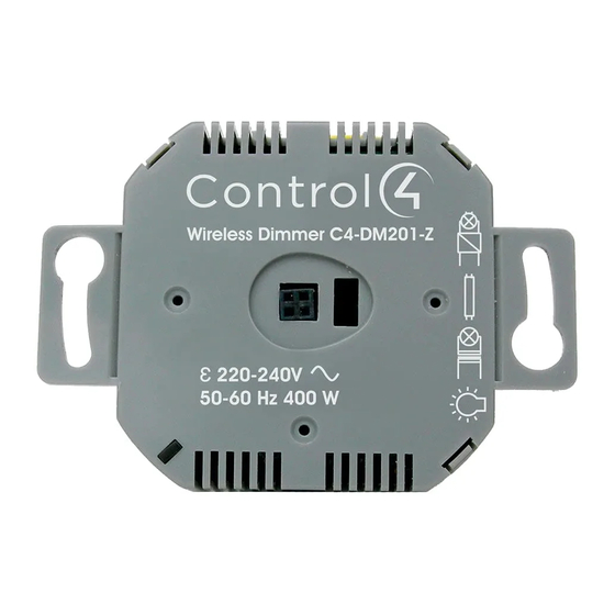
Supported Models
• C4-DM201-Z Wireless Puck Dimmer
• C4-SM201-Z Wireless Puck Switch
Box Contents
• Wireless Puck Module
• Warranty Card
• Wireless Puck Dimmer and Switch Module Installation Guide (this document)
Specifications and Supported Fixtures
Power:
220-240VAC 50/60 Hz
C4-DM201-Z
Dimmer
Supported Load Types:
Incandescent; Halogen;
Magnetic Low Voltage
(MLV); Electronic Low
Voltage (ELV); Phase-cut
dimmable: Fluorescent,
Compact Fluorescent,
and LED fixtures.
Maximum Load*
Incandescent: 400W
(@240V)
Halogen: 400W
Fluorescent: 250W
CFL: 250W
LED: 250W
Minimum Load* with
Incandescent: 5W
Neutral
Halogen: 5W
(@240V)
Fluorescent: 10W
CFL: 10W
LED: 10W
Minimum Load* with-
Incandescent: 10W
out Neutral
Halogen: 10W
(@240V)
Fluorescent: N/A
CFL: N/A
LED: N/A
Auxiliary LEDs
220-240VAC
Operating
All load ratings are based on an ambient temperature
Temperature:
of 25 degrees Celsius.
Communications:
IEEE 802.15.4, 2.4 GHz, 15-channel, spread spectrum
radio
* Notes: The maximum and minimum load requirements for fluorescent, CFL and LED loads can
vary greatly depending upon the specific fixture and/or bulb being used. At higher wattages,
these load types have significant in-rush current which can trip the protection circuitry on the
device. At low wattages, some CFL and LED loads will not be able to completely shut off.
In both cases, the quality and performance of these load types varies greatly from manufacturer
to manufacturer. When using these load types, we recommend testing in advance. If problems
are found, simply changing to a different bulb manufacturer may solve the problem.
Additionally, we do not recommend the use of fluorescent, CFL, or LED loads without a neutral
connected to the Dimmer due to the capacitive nature of these load types.
Wireless Puck
Dimmer and
Switch Module
Installation Guide
C4-SM201-Z
Switch
Incandescent; Halogen;
Magnetic Low Voltage
(MLV); Electronic Low
Voltage (ELV); Fluores-
cent; Compact Fluores-
cent; LED fixtures; and
Motors (ceiling fan and
exhaust fan).
Incandescent: 400W
Halogen: 400W
Fluorescent: 250W
CFL: 250W
LED: 250W
Motor: 1/4 HP
None
N/A
™
Load Symbols
Incandescent Lamp
Electronic Step-Down Converter
Electronic Ballast Fluorescent Lamp
Iron Core Transformer
Motors
Warnings and Considerations
WARNING!
Install in accordance with all national and local electrical
codes.
WARNING!
Improper use or installation can cause SERIOUS INJURY,
DEATH or LOSS/DAMAGE OF PROPERTY.
WARNING!
If you are unsure about any part of these instructions, consult
a qualified electrician.
WARNING!
If you are not sure which wires are Live, Load, Neutral, or
Earth/Ground, have a trained electrician perform the installation.
CAUTION!
Do not install to control a receptacle.
IMPORTANT!
Using this product in a manner other than outlined in this
document voids your warranty. Further, Control4 is NOT liable for any
damage incurred with the misuse of this product.
IMPORTANT!
Changes or modifications not expressly approved by
Control4 could void the user's authority to operate the equipment.
Installation Instructions
NOTE:
The Puck Module can be wired and installed several different
ways. Please follow the instructions below that are appropriate for your
installation.
1
Ensure that the location and intended use meet the following criteria:
• The range and performance of the wireless control system is highly
dependent on: (1) distance between devices; (2) layout of the home; (3)
walls separating the devices; and (4) electrical equipment located near the
devices.
• DO NOT exceed the maximum load rating of the device (see the previous
section, "Specifications and Supported Fixtures").
WARNING!
Disconnect the power before installing or servicing this
device.
2
Switch off and isolate the mains power at the main consumer unit or fusebox
before starting any installation or maintenance.
3
Strip each wire's insulation back 4.5 mm (3/16 in.) from the wire end.
4
If the Puck Module will be mounted to the wallbox using the yoke plate or will
be installed "floating" in the box rather than mounted to it, snap off the Puck
Module mounting ears with a pair of pliers (see Figure 1).
Figure 1. Puck Module with Removable Mounting Ears
Advertisement

Related Manuals for Control 4 C4-DM201-Z


Summary of Contents for Control 4 C4-DM201-Z
- Page 1 Switch Module Iron Core Transformer Installation Guide Motors Warnings and Considerations Supported Models • C4-DM201-Z Wireless Puck Dimmer WARNING! Install in accordance with all national and local electrical • C4-SM201-Z Wireless Puck Switch codes. WARNING! Improper use or installation can cause SERIOUS INJURY, Box Contents DEATH or LOSS/DAMAGE OF PROPERTY.
- Page 2 Figure 2. Single Location, Power at Wallbox Wiring Identify and connect the Line, Load, and Neutral (if applicable) wires to the screw terminals on the Puck Module according to the relevant wiring diagram (see Figures 2, 3, 4, or 5). The Puck Module does not require an earth ground. NOTE: Wiring configurations can differ depending upon how the fixture was wired by the electrician.
- Page 3 ™ DO NOT use with Switch Puck or with fluorescent, CFL, or LED loads...
- Page 4 Operation and Configuration Troubleshooting The Puck Module must be identified and configured using the Control4 If the load does not turn on: Composer software application. See the Composer Pro User Guide for • Ensure that the circuit breaker is not turned off or tripped. information about configuring the Puck Module.