
Summary of Contents for Teledyne FLIR SIRAS Standard Bundle
- Page 1 ™ SIRAS Standard Bundle User Manual 102-2069-40 Revision 12 January 30, 2023 ©2023 Teledyne FLIR LLC. All rights reserved. Approved for public release: Teledyne FLIR approved [FLIRGTC-SBA-011].
- Page 2 Please read this manual in its entirety and follow all guidance. Find additional information and updates at www.flir.com/siras. In the United States, drones are registered on the Federal Aviation Administration website: https://www.faa.gov/licenses_certificates/aircraft_certification/aircraft_registry/ua. ©2023 Teledyne FLIR LLC. All rights reserved. Approved for public release: Teledyne FLIR approved [FLIRGTC-SBA-011].
-
Page 3: Table Of Contents
Tap the Controller Preflight Check Button ......................63 Flight Modes (A, P, and S) ............................. 63 Turning the Motors On and Off ..........................64 Manual Joystick Operation ............................. 65 ©2023 Teledyne FLIR LLC. All rights reserved. Approved for public release: Teledyne FLIR approved [FLIRGTC-SBA-011]. - Page 4 Figure 7.B Flight Record Screen ..........................30 Figure 7.C Go Fly App Flight Control Screen ......................31 Figure 7.D Preflight Check / Flight Readiness Menu ....................33 ©2023 Teledyne FLIR LLC. All rights reserved. Approved for public release: Teledyne FLIR approved [FLIRGTC-SBA-011].
- Page 5 Figure 9.C File Manager Icon ........................... 78 Figure 9.D File Manager—microSD Card......................... 79 Figure 9.E Software Update: New Firmware ......................80 Figure 11.A MicroSD Card Slot on Aircraft ....................... 82 ©2023 Teledyne FLIR LLC. All rights reserved. Approved for public release: Teledyne FLIR approved [FLIRGTC-SBA-011].
- Page 6 This is an informational notice, calling attention to an important detail. ☛ This is a tip that can improve your effectiveness in using the product. ©2023 Teledyne FLIR LLC. All rights reserved. Approved for public release: Teledyne FLIR approved [FLIRGTC-SBA-011].
-
Page 7: Siras Documentation
Wall power supply to USB type C connector Upon release starting in 2023, additional or alternative payloads will be available. Check with your dealer for features and pricing. ©2023 Teledyne FLIR LLC. All rights reserved. Approved for public release: Teledyne FLIR approved [FLIRGTC-SBA-011]. -
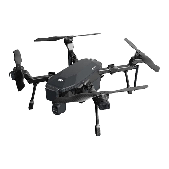
Page 8: Figure 2.A Siras Standard Bundle
Detection Range of 0.91 m to 30.5 m (3 ft to 100 ft) at an Effective Forward Obstacle Detection Speed of <5 m/s (11 mph) ©2023 Teledyne FLIR LLC. All rights reserved. Approved for public release: Teledyne FLIR approved [FLIRGTC-SBA-011]. - Page 9 6,000 mAh Voltage 15.2 V Battery Type LiPo 4S Operating Temperature 5⁰C to 50⁰C (41⁰F to 122⁰F) Maximum Charge Current REMOTE CONTROLLER Frequency Dual-band 2.4/5.8 GHz ©2023 Teledyne FLIR LLC. All rights reserved. Approved for public release: Teledyne FLIR approved [FLIRGTC-SBA-011].
-
Page 10: Siras Aircraft
18. LED Light - Aircraft Direction Indicator (2 White and 2 Red) 19. Battery Power Level Button 20. Battery Status Indicator FIGURE 3.A SIRAS AIRCRAFT FRONT AND REAR VIEW ©2023 Teledyne FLIR LLC. All rights reserved. Approved for public release: Teledyne FLIR approved [FLIRGTC-SBA-011]. -
Page 11: Siras Controller
Flight Mode: Attitude (A), Position (P), Sport (S) Return to Home 10. Controller Power (On/Off) 11. Capture FIGURE 4.A SIRAS CONTROLLER (FRONT AND TOP VIEW) ©2023 Teledyne FLIR LLC. All rights reserved. Approved for public release: Teledyne FLIR approved [FLIRGTC-SBA-011]. -
Page 12: Figure 4.B Siras Controller User Interface Ports
Position or Sport Modes. See 8.H, Flight Modes (A, P, and Return to Home The “House” button initiates a Return to Home action. See 8.N, Return to Home. ©2023 Teledyne FLIR LLC. All rights reserved. Approved for public release: Teledyne FLIR approved [FLIRGTC-SBA-011]. -
Page 13: Controller Led Definitions And Functions
Signal Quality Signal Quality Signal Quality Signal Quality Signal Lost Transmission Signal Status 100% 66%~99% 33%~65% 1%~32% TABLE 4.D CONTROLLER (BOTTOM ROW) LED BATTERY STATUS ©2023 Teledyne FLIR LLC. All rights reserved. Approved for public release: Teledyne FLIR approved [FLIRGTC-SBA-011]. -
Page 14: Controller Battery Charging
4.D, item 14. Insert the microSD card into the slot (contacts up) and press it in until it engages and is held in place. The ©2023 Teledyne FLIR LLC. All rights reserved. Approved for public release: Teledyne FLIR approved [FLIRGTC-SBA-011]. -
Page 15: Controller Antenna
SIRAS, as shown in Figure 4.E. FIGURE 4.E EXPAND AND FOLD THE ANTENNA FOR OPERATION AND STORAGE ©2023 Teledyne FLIR LLC. All rights reserved. Approved for public release: Teledyne FLIR approved [FLIRGTC-SBA-011]. -
Page 16: Aircraft Battery Safety / Charging
Batteries will drain (very slowly) even when not in the aircraft – this is another reason to keep them charged. ⚠ See additional warnings on the battery label. ©2023 Teledyne FLIR LLC. All rights reserved. Approved for public release: Teledyne FLIR approved [FLIRGTC-SBA-011]. -
Page 17: Aircraft Battery Charging Instructions
● ✹ >40% ○ ● ● ● ✹ >60% ● ● ● ● ✹ >80% ● ● ● ● ● 100% ○ ● ✹ FLASH ©2023 Teledyne FLIR LLC. All rights reserved. Approved for public release: Teledyne FLIR approved [FLIRGTC-SBA-011]. -
Page 18: Table 5.B Charger Error Messages
○ OFF ● FLASH * Contact FLIR Service + Allow cooling before charging batteries ** Warm batteries to at least 5 C (41⁰F) before charging ©2023 Teledyne FLIR LLC. All rights reserved. Approved for public release: Teledyne FLIR approved [FLIRGTC-SBA-011]. -
Page 19: Aircraft Battery Charger Performance As A Function Of Temperature
16⁰C −45⁰C (61⁰F – 113⁰F) Normal 6A Charge 46⁰C −50⁰C (115⁰F – 122⁰F) 1.2A Slow Charge No Charge - Error LED will illuminate > 50⁰C (122⁰F ©2023 Teledyne FLIR LLC. All rights reserved. Approved for public release: Teledyne FLIR approved [FLIRGTC-SBA-011]. -
Page 20: Reparing The Siras Aircraft For Flight
(CW or CCW). When replacing the propellers, refer to Figure 6.A for correct orientation. FIGURE 6.A PROPELLER ROTATION ORIENTATION (TOP VIEW ) ©2023 Teledyne FLIR LLC. All rights reserved. Approved for public release: Teledyne FLIR approved [FLIRGTC-SBA-011]. -
Page 21: Extending And Folding The Aircraft Arms
Two of the aircraft arms have antennas. Do not apply force to the antennas when extending and folding the aircraft arms. ☛ For best communication results, leave the antennas pointing down. FIGURE 6.B EXTENDING (LEFT) AND LOCKING (RIGHT) THE AIRCRAFT ARMS ©2023 Teledyne FLIR LLC. All rights reserved. Approved for public release: Teledyne FLIR approved [FLIRGTC-SBA-011]. -
Page 22: Installing The Aircraft Batteries
Insert the upper battery with the locking tabs facing down. FIGURE 6.C INSTALLING THE LOWER (LEFT) AND UPPER (RIGHT) BATTERIES ©2023 Teledyne FLIR LLC. All rights reserved. Approved for public release: Teledyne FLIR approved [FLIRGTC-SBA-011]. -
Page 23: Figure 6.D Locking The Batteries In The Aircraft
The battery operating temperature is 5⁰C to 50⁰C (41⁰F to 122⁰F). SIRAS operating temperature is −10⁰C to 40⁰C (14⁰F to 104⁰F). If the batteries are colder than 5⁰C (41⁰F), they will likely not operate properly. ©2023 Teledyne FLIR LLC. All rights reserved. Approved for public release: Teledyne FLIR approved [FLIRGTC-SBA-011]. - Page 24 As previously noted, use batteries with matching charge levels. ⚠ Do not hot swap batteries if the ambient temperature exceeds 37°C (100°F). ©2023 Teledyne FLIR LLC. All rights reserved. Approved for public release: Teledyne FLIR approved [FLIRGTC-SBA-011].
-
Page 25: Installing And Removing The Payload
To remove the payload, depress the gimbal tabs and gently slide the gimbal away from the aircraft body until it is free of the rails. FIGURE 6.E CONNECT THE PAYLOAD USING THE QUICK RELEASE, RAILS, AND CONNECTOR ©2023 Teledyne FLIR LLC. All rights reserved. Approved for public release: Teledyne FLIR approved [FLIRGTC-SBA-011]. -
Page 26: Powering On The Aircraft And Controller
The manufacturer has established the pairing settings between the controller and the aircraft. If pairing settings need to be re-established, see the instructions in section 7.B6ii. ©2023 Teledyne FLIR LLC. All rights reserved. Approved for public release: Teledyne FLIR approved [FLIRGTC-SBA-011]. -
Page 27: Powering Off The Controller And Aircraft
FIGURE 6.H POWER OFF MENU To power off the aircraft, press and release the power button. Then press and hold the power button for two seconds. ©2023 Teledyne FLIR LLC. All rights reserved. Approved for public release: Teledyne FLIR approved [FLIRGTC-SBA-011]. -
Page 28: Aircraft Indicator Lights
● LED 7 LED off: Pressure is stable LED blinking blue: GPS convergence is not complete ● LED 8 LED off: GPS convergence is complete ©2023 Teledyne FLIR LLC. All rights reserved. Approved for public release: Teledyne FLIR approved [FLIRGTC-SBA-011]. -
Page 29: Controller: The Go Fly Application
Status page will display error lists (if any) from recent flights to help pilots diagnose issues with the aircraft. For example, if low remaining battery levels trigger the automatic Return to Home feature, a record of this event will appear. ©2023 Teledyne FLIR LLC. All rights reserved. Approved for public release: Teledyne FLIR approved [FLIRGTC-SBA-011]. -
Page 30: Figure 7.B Flight Record Screen
Touch the screen and slide up or down to scroll through records. Tap on a flight record to have the controller display a flight map. Go Fly Application Tap the Go Fly button to launch the flight control screen (Figure 7.C). ©2023 Teledyne FLIR LLC. All rights reserved. Approved for public release: Teledyne FLIR approved [FLIRGTC-SBA-011]. -
Page 31: Go Fly Application Features
Thermal, Visible, or MSX ; display resolution and modes 7. Camera Viewing Mode (7.B7) 8. Photo/Video Selection and Settings Photo modes: still or video, with related settings (7.B8) ©2023 Teledyne FLIR LLC. All rights reserved. Approved for public release: Teledyne FLIR approved [FLIRGTC-SBA-011]. -
Page 32: Table 7.B Connection Status And Error Indicators
Noisy environment: There is too much interference in the area for the compass to be calibrated. Diagnostic: The red gauge is a diagnostic indicator to aid service (gauge) technicians and can be ignored by pilots. ©2023 Teledyne FLIR LLC. All rights reserved. Approved for public release: Teledyne FLIR approved [FLIRGTC-SBA-011]. -
Page 33: Figure 7.D Preflight Check / Flight Readiness Menu
FIGURE 7.D PREFLIGHT CHECK / FLIGHT READINESS MENU Controller and Aircraft Signal and Battery Levels Group 5 in Figure 7.C displays the signal and battery indicators, as described in the following table. ©2023 Teledyne FLIR LLC. All rights reserved. Approved for public release: Teledyne FLIR approved [FLIRGTC-SBA-011]. -
Page 34: Figure 7.E Safety Menu (Part 1)
Use the touchscreen to drag the menu upward and view the lower half. FIGURE 7.E SAFETY MENU (PART 1) ©2023 Teledyne FLIR LLC. All rights reserved. Approved for public release: Teledyne FLIR approved [FLIRGTC-SBA-011]. -
Page 35: Figure 7.F Safety Menu (Part 2; Scroll Down To View)
Set these levels by tapping the green status dot in the menu. Slider bars for the first and second alarms will appear. When10% battery charge is remaining, SIRAS will automatically return to home. ©2023 Teledyne FLIR LLC. All rights reserved. Approved for public release: Teledyne FLIR approved [FLIRGTC-SBA-011]. -
Page 36: Figure 7.G Control Menu (Part 1)
Stick Mode: Set the joystick mode. Mode 2 is the default setting, in which the right stick controls roll and pitch while the left stick controls yaw and up/down motion (throttle). See 8-J, Manual Joystick Operation. Mode 1 is also available. ©2023 Teledyne FLIR LLC. All rights reserved. Approved for public release: Teledyne FLIR approved [FLIRGTC-SBA-011]. -
Page 37: Figure 7.H Control Menu (Part 2, Scroll Down To View)
However, some pilots may purchase a second controller for extended flight days, in which case pairing will be required. FIGURE 7.H CONTROL MENU (PART 2, SCROLL DOWN TO VIEW) ©2023 Teledyne FLIR LLC. All rights reserved. Approved for public release: Teledyne FLIR approved [FLIRGTC-SBA-011]. -
Page 38: Figure 7.I Pairing Button Cover
Bring the controller near the aircraft to be paired and extend the controller’s antenna. Power the controller on and go to the Control Menu, as shown in Figure 7.H. Tap Pair in the Control Menu. ©2023 Teledyne FLIR LLC. All rights reserved. Approved for public release: Teledyne FLIR approved [FLIRGTC-SBA-011]. -
Page 39: Figure 7.J Pressing The Pair Button (Pairing Light Flashing)
FIGURE 7.J PRESSING THE PAIR BUTTON (PAIRING LIGHT FLASHING) In the next dialog (Step 3), tap Remote Controller Pairing, as shown in Figure 7.K. FIGURE 7.K PAIRING, STEP 3 ©2023 Teledyne FLIR LLC. All rights reserved. Approved for public release: Teledyne FLIR approved [FLIRGTC-SBA-011]. -
Page 40: Figure 7.L Control Menu (Part 3, Scroll Down To View)
Gimbal Calibration: Tap the Calibration to initiate gimbal calibration, which ensures that the gimbal can properly orient itself. ©2023 Teledyne FLIR LLC. All rights reserved. Approved for public release: Teledyne FLIR approved [FLIRGTC-SBA-011]. -
Page 41: Figure 7.M Control Menu (Part 4, Scroll Down To View)
“Camera Zoom” or Gimbal Pan. The operation of the right wheel is described in 8.K2. The left wheel cannot be remapped; it always controls the gimbal tilt. ©2023 Teledyne FLIR LLC. All rights reserved. Approved for public release: Teledyne FLIR approved [FLIRGTC-SBA-011]. -
Page 42: Figure 7.N Camera Menu
If the aircraft’s software is out-of-date relative to the controller software, this box will display an Update button (see Chapter 9, Updating the Controller and Aircraft Firmware). ©2023 Teledyne FLIR LLC. All rights reserved. Approved for public release: Teledyne FLIR approved [FLIRGTC-SBA-011]. -
Page 43: Figure 7.O Visible Camera Quick-Access Features
When the V (visible) icon is selected, icons appear to its left, as shown in Figure 7.O. These are described in Table 7.D. FIGURE 7.O VISIBLE CAMERA QUICK-ACCESS FEATURES ©2023 Teledyne FLIR LLC. All rights reserved. Approved for public release: Teledyne FLIR approved [FLIRGTC-SBA-011]. -
Page 44: Table 7.D Visible Camera Quick-Access Features
HD resolution. If you clear HD, the Zoom level reverts to x1. ☛ Only use HD mode when the aircraft is stationary, or you may observe pixilation and increased image latency on the controller display. ©2023 Teledyne FLIR LLC. All rights reserved. Approved for public release: Teledyne FLIR approved [FLIRGTC-SBA-011]. -
Page 45: Figure 7.P The Video Resolution Icon (Visible Light / Video)
EV icon. Brightness can be adjusted on a scale from −2 (darker) to +2 (brighter) to prevent imagery from being too dark or too light. ©2023 Teledyne FLIR LLC. All rights reserved. Approved for public release: Teledyne FLIR approved [FLIRGTC-SBA-011]. -
Page 46: Figure 7.Q Thermal Camera Quick-Access Features
(see the right wheel assignment paragraph in 7.B6ii). Note that additional thermal camera features are accessed via the Gear icon ( ) below the Shutter button and are described in detail in 7.B8iii. ©2023 Teledyne FLIR LLC. All rights reserved. Approved for public release: Teledyne FLIR approved [FLIRGTC-SBA-011]. -
Page 47: Figure 7.R Thermal Plus Visual Display
To enable the visible and thermal split screen mode, engage either the thermal T or visible V icon, then touch and hold down the other T or V icon so that both are illuminated. FIGURE 7.R THERMAL PLUS VISUAL DISPLAY ©2023 Teledyne FLIR LLC. All rights reserved. Approved for public release: Teledyne FLIR approved [FLIRGTC-SBA-011]. -
Page 48: Figure 7.S Msx Mode (Outlined Thermal) Photo
View the photo by tapping Replay ( ). An example of an MSX image is shown in Figure 7.S. FIGURE 7.S MSX MODE (OUTLINED THERMAL) PHOTO ©2023 Teledyne FLIR LLC. All rights reserved. Approved for public release: Teledyne FLIR approved [FLIRGTC-SBA-011]. -
Page 49: Figure 7.T Shutter Controls
The top pair of icons are the Still Camera ( ) and Video Camera ( ) icons. Whichever is highlighted in green is the current camera mode. ©2023 Teledyne FLIR LLC. All rights reserved. Approved for public release: Teledyne FLIR approved [FLIRGTC-SBA-011]. -
Page 50: Figure 7.U Button To Expose Hidden Shutter Controls
(single shot, burst of shots, and shot intervals). It also allows you to select the image format, though currently, only JPEG is available (see Figure 7.V). ©2023 Teledyne FLIR LLC. All rights reserved. Approved for public release: Teledyne FLIR approved [FLIRGTC-SBA-011]. -
Page 51: Figure 7.V Capture Mode And Image Format Settings For Visible Camera
Camera icon highlighted ( ). This menu allows adjustment of the capture mode and image format. The available capture modes are single-shot, a burst of ©2023 Teledyne FLIR LLC. All rights reserved. Approved for public release: Teledyne FLIR approved [FLIRGTC-SBA-011]. -
Page 52: Figure 7.X Video Format Settings For Thermal Camera
) to select the video format. Either MOV or CSQ (compressed sequence, 16-bit thermal data) are available. FIGURE 7.X VIDEO FORMAT SETTINGS FOR THERMAL CAMERA ©2023 Teledyne FLIR LLC. All rights reserved. Approved for public release: Teledyne FLIR approved [FLIRGTC-SBA-011]. -
Page 53: Figure 7.Y Radiometric Adjustments For Thermal Camera
The vertical green bar indicates gimbal tilt, where 15° is slightly above horizontal and −90° is straight down. Gimbal tilt is controlled by the left scroll wheel (8.K1) and by the Payload Angle icon (7.B11). ©2023 Teledyne FLIR LLC. All rights reserved. Approved for public release: Teledyne FLIR approved [FLIRGTC-SBA-011]. -
Page 54: Figure 7.Z Map Activated
Displayed in the lower left corner is a circle describing aircraft attitude, as well as a compass heading on the outer circle, roll and pitch as an artificial horizon, and pitch in degrees. To its right is a the horizontal bar ©2023 Teledyne FLIR LLC. All rights reserved. Approved for public release: Teledyne FLIR approved [FLIRGTC-SBA-011]. -
Page 55: Figure 7.Bb Engagement Of The Collision Avoidance Feature
A large display message will pop up on the screen when Collision Avoidance is turned on, as seen in Figure 7.BB. FIGURE 7.BB ENGAGEMENT OF THE COLLISION AVOIDANCE FEATURE ©2023 Teledyne FLIR LLC. All rights reserved. Approved for public release: Teledyne FLIR approved [FLIRGTC-SBA-011]. -
Page 56: Msx Mode
C. MSX Mode MSX is a patented Teledyne FLIR imaging technology that produces richly-detailed thermal images by bringing together the visual and thermal spectrums. MSX uses a high-contrast visual image to emboss key aspects of the scene on top of a full thermal image. See 7.B7iv... -
Page 57: Flying The Siras Aircraft
8.B. Continue beyond 360⁰ until the controller indicates that this step is complete. ☛ Move smoothly and slowly. ☛ Hold the aircraft at least 3 ft (1m) above the ground to avoid ground-based interference. ©2023 Teledyne FLIR LLC. All rights reserved. Approved for public release: Teledyne FLIR approved [FLIRGTC-SBA-011]. -
Page 58: Figure 8.A Calibrate Compass: Prompt 2
The third prompt directs the operator to hold the aircraft nose-up while rotating it 360⁰ in the horizontal plane. Again, continue beyond 360⁰ until the controller indicates that this step is complete. ©2023 Teledyne FLIR LLC. All rights reserved. Approved for public release: Teledyne FLIR approved [FLIRGTC-SBA-011]. -
Page 59: Figure 8.C Compass Calibration Step 3: Horizontal Rotation, Nose-Up
5. The controller will indicate the quality of calibration. Excellent is shown in Figure 8.D Other outcomes are Good, Poor, and Bad. A Bad rating indicates a failure. FIGURE 8.D COMPASS CALIBRATION SUCCESSFUL ©2023 Teledyne FLIR LLC. All rights reserved. Approved for public release: Teledyne FLIR approved [FLIRGTC-SBA-011]. -
Page 60: Precautions Before Flying
If this happens, SIRAS will return to home (RTH) with Collision Avoidance enabled. To take SIRAS out of RTH mode once the connection has been restored (which usually ©2023 Teledyne FLIR LLC. All rights reserved. Approved for public release: Teledyne FLIR approved [FLIRGTC-SBA-011]. - Page 61 15. After a fire, explosion, earthquake, flood, lightning strike, or other disasters, ensure safety at the takeoff and landing points and be observant as the situation changes. Attend to your safety as well. ©2023 Teledyne FLIR LLC. All rights reserved. Approved for public release: Teledyne FLIR approved [FLIRGTC-SBA-011].
-
Page 62: Preflight Check
Unfold the controller antennas as shown in Figure 4.E. F. Power On the Aircraft and Controller Power on the aircraft and controller as described in section 6.E. ©2023 Teledyne FLIR LLC. All rights reserved. Approved for public release: Teledyne FLIR approved [FLIRGTC-SBA-011]. -
Page 63: Tap The Controller Preflight Check Button
Gust Warning (any Mode) The aircraft will automatically reduce speed to maintain stability in windy conditions. When this happens, a Gust warning message is displayed on the controller. ©2023 Teledyne FLIR LLC. All rights reserved. Approved for public release: Teledyne FLIR approved [FLIRGTC-SBA-011]. -
Page 64: Turning The Motors On And Off
Take the aircraft out of locked mode and start the propellers by pulling both controller sticks toward you and inward, as shown in FIGURE 8.E TURNING MOTORS ON (LEFT) AND OFF (RIGHT) ☛ The motors power off automatically when the aircraft lands. ©2023 Teledyne FLIR LLC. All rights reserved. Approved for public release: Teledyne FLIR approved [FLIRGTC-SBA-011]. -
Page 65: Manual Joystick Operation
Moving the joystick to the left will roll the aircraft to that side and cause it to slide left without yawing. ©2023 Teledyne FLIR LLC. All rights reserved. Approved for public release: Teledyne FLIR approved [FLIRGTC-SBA-011]. -
Page 66: Scroll Wheels: Camera Aiming And Zoom
The Collision Avoidance system is not effective at aircraft speeds faster than 5 m/s (11 mph). Collision Avoidance is automatically activated when the Return to Home feature is selected. ©2023 Teledyne FLIR LLC. All rights reserved. Approved for public release: Teledyne FLIR approved [FLIRGTC-SBA-011]. -
Page 67: Return To Home
In Mission Planning mode, the controller swaps the map and image, and new controls appear, as shown in Figure (In the Figure, the Add New and Load controls are also shown, as if the Waypoint Tool (item 1) has just been tapped). ©2023 Teledyne FLIR LLC. All rights reserved. Approved for public release: Teledyne FLIR approved [FLIRGTC-SBA-011]. -
Page 68: Figure 8.G Mission Planning (Waypoint) Controls
SIRAS Standard Bundle User Manual Revision 12 FIGURE 8.G MISSION PLANNING (W AYPOINT) CONTROLS ©2023 Teledyne FLIR LLC. All rights reserved. Approved for public release: Teledyne FLIR approved [FLIRGTC-SBA-011]. -
Page 69: Table 8.A Mission Planning (Waypoint) Controls
At this point, you may tap anywhere on the map to create a new waypoint. You do not need to tap the Waypoint Tool ( ). The controller will display the waypoint in blue, along with a line segment ©2023 Teledyne FLIR LLC. All rights reserved. Approved for public release: Teledyne FLIR approved [FLIRGTC-SBA-011]. -
Page 70: Figure 8.H Drawing The First Two Waypoints
Figure 8.I. On this menu, tap the ( ) link to pull up the Waypoint Type menu. The waypoint types are described in Table 8.B. ©2023 Teledyne FLIR LLC. All rights reserved. Approved for public release: Teledyne FLIR approved [FLIRGTC-SBA-011]. -
Page 71: Figure 8.I Waypoint Settings And Types
The Waypoint Settings menu includes the following controls. The menu is large and extends beyond the display screen. Use the touchscreen to drag the menu upward and view the lower half. ©2023 Teledyne FLIR LLC. All rights reserved. Approved for public release: Teledyne FLIR approved [FLIRGTC-SBA-011]. -
Page 72: Table 8.C Waypoint Settings
A preplanned mission can only capture still pictures. It cannot capture videos. A preplanned mission cannot change camera settings, including the Zoom setting. ©2023 Teledyne FLIR LLC. All rights reserved. Approved for public release: Teledyne FLIR approved [FLIRGTC-SBA-011]. -
Page 73: Figure 8.J Waypoint Symbols On A Map
A waypoint can only have one type. You cannot take a picture at a Return to Home waypoint, but you can add a Return to Home waypoint just beyond the last camera waypoint. ©2023 Teledyne FLIR LLC. All rights reserved. Approved for public release: Teledyne FLIR approved [FLIRGTC-SBA-011]. -
Page 74: Figure 8.K Using The Keyboard To Name The Mission
A mission must take off from the ground. You may not hover and then start a mission. You cannot start a mission unless Collision Avoidance is set to On. You may need to set it manually. ©2023 Teledyne FLIR LLC. All rights reserved. Approved for public release: Teledyne FLIR approved [FLIRGTC-SBA-011]. - Page 75 ) button. The aircraft will lift off and begin flying to its first waypoint. ⚠ Observe the flight carefully. Be prepared to take manual control (by switching Mission to OFF) if the aircraft is flying dangerously. ©2023 Teledyne FLIR LLC. All rights reserved. Approved for public release: Teledyne FLIR approved [FLIRGTC-SBA-011].
-
Page 76: Updating The Controller And Aircraft Firmware
The steps to update the controller application and the aircraft firmware are as follows: 1. Power off the aircraft and the controller. 2. Download the update files from the Teledyne FLIR support site at www.flir.com/siras to a PC that has a microSD card reader. -
Page 77: Figure 9.A Swipe Left To Expose The Android Icons
To expose the Android icons from the SIRAS application opening screen, swipe left from the screen’s right-hand edge, as shown in Figure 9.A. FIGURE 9.A SWIPE LEFT TO EXPOSE THE ANDROID ICONS ©2023 Teledyne FLIR LLC. All rights reserved. Approved for public release: Teledyne FLIR approved [FLIRGTC-SBA-011]. -
Page 78: Figure 9.B Tap The Circle Icon
FIGURE 9.B TAP THE CIRCLE ICON c. Select the File Manager icon (If it does not automatically appear, swipe from below and tap it). FIGURE 9.C FILE MANAGER ICON ©2023 Teledyne FLIR LLC. All rights reserved. Approved for public release: Teledyne FLIR approved [FLIRGTC-SBA-011]. -
Page 79: Figure 9.D File Manager-Microsd Card
If you tap DONE instead of OPEN, the next time you run the Go Fly app, you will be prompted to continue installing the aircraft firmware (assuming it is out-of-date with the controller software). ©2023 Teledyne FLIR LLC. All rights reserved. Approved for public release: Teledyne FLIR approved [FLIRGTC-SBA-011]. -
Page 80: Figure 9.E Software Update: New Firmware
If the update fails, wait a few seconds, check the proximity of the controller to the aircraft, and tap Retry in the failure message. 17. Power off the drone and power it back on. ©2023 Teledyne FLIR LLC. All rights reserved. Approved for public release: Teledyne FLIR approved [FLIRGTC-SBA-011]. -
Page 81: Loading Maps Into The Controller
Download one or more maps onto the controller SD card into the directory <drive>:\FlyWatch\map. Eject the microSD card from your PC and reinsert it into the controller. ©2023 Teledyne FLIR LLC. All rights reserved. Approved for public release: Teledyne FLIR approved [FLIRGTC-SBA-011]. -
Page 82: Aircraft Memory Card
SD card slot, as shown in Figure 11.A. FIGURE 11.A MICROSD CARD SLOT ON AIRCRAFT ©2023 Teledyne FLIR LLC. All rights reserved. Approved for public release: Teledyne FLIR approved [FLIRGTC-SBA-011]. - Page 83 Always fly with a microSD card inserted in the aircraft. ⚠ Insert the microSD card fully into its slot, ensuring that the catch is engaged. Cover the slot. ©2023 Teledyne FLIR LLC. All rights reserved. Approved for public release: Teledyne FLIR approved [FLIRGTC-SBA-011].
-
Page 84: Product Registration
For product support, please register the SIRAS airframe and payload at www.flir.com/register. Table 12.A Serial Numbers 1. Payload Serial Number 2. Airframe Serial Number FIGURE 12.A PAYLOAD AND AIRFRAME SERIAL NUMBER LOCATIONS ©2023 Teledyne FLIR LLC. All rights reserved. Approved for public release: Teledyne FLIR approved [FLIRGTC-SBA-011]. -
Page 85: Warranty And Notices
This is to prevent water from infiltrating the internal parts, which can impact the IP protection capability of the aircraft. ©2023 Teledyne FLIR LLC. All rights reserved. Approved for public release: Teledyne FLIR approved [FLIRGTC-SBA-011]. -
Page 86: Legal Obligations
You will not fly near the flight paths of airplanes and ensure that the aircraft will not cause any impact to any aircraft on the flight path. Please always remain cautious and avoid any other aircraft, and land immediately when necessary. ©2023 Teledyne FLIR LLC. All rights reserved. Approved for public release: Teledyne FLIR approved [FLIRGTC-SBA-011]. - Page 87 The Manufacturer / Marketer / Distributor are entitled to the right to modify, change or terminate the provisions without prior notification. ©2023 Teledyne FLIR LLC. All rights reserved. Approved for public release: Teledyne FLIR approved [FLIRGTC-SBA-011].
- Page 88 (EMC). Any end-product intended for general consumer use that incorporates this device must be tested in accordance and comply with all applicable EU EMC and other relevant directives. ©2023 Teledyne FLIR LLC. All rights reserved. Approved for public release: Teledyne FLIR approved [FLIRGTC-SBA-011].
Need help?
Do you have a question about the FLIR SIRAS Standard Bundle and is the answer not in the manual?
Questions and answers
My flight log is not showing up. I've gone into the flight log area, updated the dates I want to search and it shows no flights even though I flew.