Table of Contents
Advertisement
Quick Links
Advertisement
Table of Contents

Summary of Contents for GKD SENSORZONE
- Page 1 PROXIMITY WARNING SYSTEM (WIFI) V2.0 INSTALLATION MANUAL COPYRIGHT NOTICE Intended audience: This document contains sensitive information. It may not be shared with other parties without the express written permission of GKD Technologies Ltd. M4000002 V2.5 - 05/2022...
-
Page 2: Table Of Contents
CONTENTS Page SAFETY AND WARNINGS General Devices Containing Batteries 1.2.1 Tags 1.2.2 Base Stations and Tag Test Units Antenna Magnets 2 GENERAL INTRODUCTION System Summary System Components 3 PLANNING / SITE SURVEY 4 MACHINE INSTALLATION Antenna 4.1.1 Operator Tag Considerations Base Station Display Beacon Sounder... - Page 3 Page 5 INTEGRATION WITH HANDBRAKE OR DEAD MAN’S HANDLE 6 SITE INSTALLATION Tag Test Unit 7 CONFIGURATION Login Screen Configuration Page Log Page Tag Page Logout Advanced Page APPENDIX A - WIRING DIAGRAMS APPENDIX B - HOW TO MAKE A CONNECTOR APPENDIX C - TRACKUNIT CONNECTION www.gkdtechnologies.com M4000002 V2.5 - 05 /2022...
-
Page 4: Safety And Warnings
All electrical installation must follow local regulations and be made by qualified installers. The SensorZone proximity warning system is only to be used as a complement to existing Health and Safety measures and practices. The use of SensorZone does not replace professional machinery safe operating processes and procedures. -
Page 5: Base Stations And Tag Test Units
1.2.1.1 Damaged Tags If you suspect the tag has suffered impact or maybe damaged in any way that may damage the battery DO NOT USE. The tag should be removed and quarantined. DO NOT attempt to take the tag apart. Follow local regulations for the safe disposal of units containing damaged batteries. -
Page 6: General Introduction
2 GENERAL INTRODUCTION The SensorZone Proximity Warning System (PWS) is complimentary to (and not a substitute for) existing safe systems and procedures of work. SensorZone is a robust, high-quality Collision Avoidance System – also known as a Proximity Warning System – with a proven track record for improving safety in the workplace. -
Page 7: Planning / Site Survey
3 PLANNING / SITE SURVEY The installation and commissioning of the SensorZone system requires consideration of the safety objectives of the site, the types of equipment in use and the nature of the operation. The following steps are envisaged: Obtain a map of the site... -
Page 8: Machine Installation
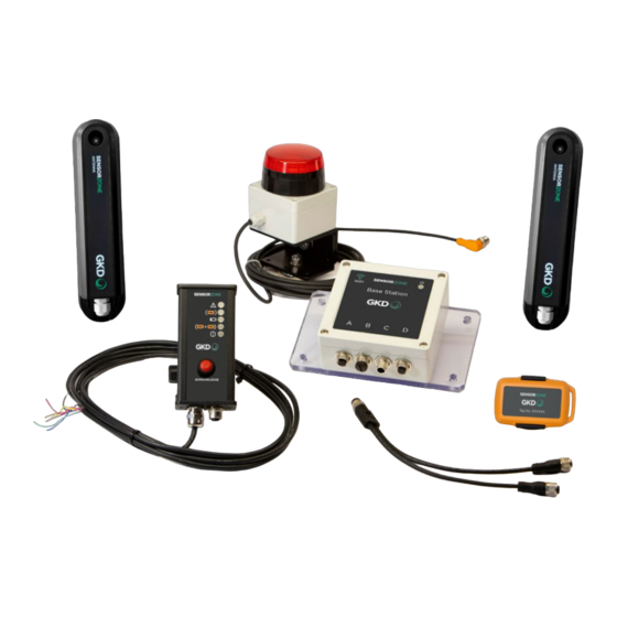
4 MACHINE INSTALLATION There are four parts of the system to install in the vehicle: Antenna Base Station Operator Display Sounder / Beacon (one or two) (or Push Button) (optional) The wiring for the in-vehicle components is dependent on the type of display and number of antennas. - Page 9 Excavator – rear and sides monitoring For guidance on detection zone sizing, scan here. Excavator - all round monitoring Dozer – As a rule all around monitoring is required. Recommended installation position is on the vehicle roof. Wheel Loader - As a rule all around monitoring is required.
-
Page 10: Operator Tag Considerations
4.1.1 Operator Tag Considerations The operator of the machine must be wearing a tag. As this is a requirement of the initialisation of the system, the exclusion zone must include the cab or operators position of the machine. The operator tag will not If a rear detection range The operator tag be seen when the operator is... -
Page 11: Beacon Sounder
The operator display should be mounted in a place that is protected from heavy rain and jet washing, and is normally intended to be mounted inside the cab. Where out-of-cab or open cab operation is required, the push button display should be used. Beacon Sounder The beacon sounder should be mounted such that it is visible to pedestrians outside of the machine. -
Page 12: Integration With Handbrake Or Dead Man's Handle
The handbrake or dead man’s handle must be connected into the SensorZone Operator Display for these modes to become active. They cannot be connected to either the SensorZone Push Button Display or the Wireless Display. Description of the modes 5.3.1 Mode 1 –... - Page 13 SensorZone system. This mode can be used to reduce the occurrence of alerts when pedestrians are required to make authorised approaches to a stationary vehicle.
-
Page 14: Site Installation
6 SITE INSTALLATION In addition to the vehicle installation, the following equipment is installed on the site: Tag Test Unit The tag test unit should be installed in a convenient place that allows all personnel going onto or leaving the site to test their tags. -
Page 15: Configuration
Important Note: Below are the default username and passwords. **Please change these once you have logged into the system.** For SensorZone User: Username: user Password: user For SensorZone Installer: Username: installer Password: installer www.gkdtechnologies.com... -
Page 16: Configuration Page
Configuration Page: The default page after logging in is the configuration page. Note that options available on this page may be different depending on the level of the logged in user. Displays the latest recorded system events Displays basic information about the base station, system set up and the firmware versions installed. - Page 17 Configuration changes: a. Use [Set Time/Date] to set the base station time and date to match the settings from the browser/PC b. Use [Range 1] and [Range 2] to set the ranges for the exclusion zone as described in Section 2 above c.
-
Page 18: Log Page
Log Page: All events recorded on the base station are stored in a log file. To access the log file, click on [Read Log]. Note that this can take several minutes depending on the size of the log file. The Read Progress bar will show the status of the read. -
Page 19: Tag Page
Tag Page: This page provides information about tags in range. Click on [Update Tag List] to populate the list of tags that are currently in the exclusion zone. Tags in the exclusion zone will appear in the tag list box. Logout To logout, click the Logout Tab. -
Page 20: Advanced Page
For convenience, this is printed on the label on the side of the base station. If the WiFi passcode is lost, contact your distributor or GKD for assistance. [Date Format Configuration] can be used to modify how the date is displayed. -
Page 21: Appendix A - Wiring Diagrams
1 (Brown) - CAN L pin 2 (White) - Positive input voltage pin 3 (Blue) - Negative input voltage pin 4 (Black) - CAN H OPTIONAL SensorZone Connectivity Module (See Appendix C for more information) 8-way Flying Lead from Display... - Page 22 2 (White) - Positive input voltage Dual Antenna Y-Cable pin 3 (Blue) - Negative input voltage Part Number: P4000015 pin 4 (Black) - CAN H OPTIONAL SensorZone Connectivity Module (See Appendix C for more information) 8-way Flying Lead from Display Positive 12/24V...
- Page 23 Single Antenna with Push Button Display Connector A on Base Station Connector D on Base Station M12 4-way Female - Male M12 4-way Male pin 1 (Brown) - Detect pin 1 (Brown) - Relay output, positive when system active pin 2 (White) - Antenna pin 2 (White) - Relay output, positive when incursion present pin 3 (Blue) - Detect pin 3 (Blue) - Negative output for system active...
- Page 24 APPENDIX A - WIRING DIAGRAMS FOR THE EQUIPMENT ON VEHICLE (continued) Dual Antenna with Push Button Display To Dual Antenna Y-Cable Connector D on Base Station M12 4-way Female - Male (x2) M12 4-way Male pin 1 (Brown) - Detect pin 1 (Brown) - Relay output, positive when system active pin 2 (White) - Antenna pin 2 (White) - Relay output, positive when incursion present...
-
Page 25: Appendix B - How To Make A Connector
APPENDIX B - HOW TO MAKE A CONNECTOR There are four individual connector components: Connector Connector Rubber Cable Body Housing O-Ring Clamp Slide the cable clamp, rubber o-ring and connector housing onto the end of the cable. Attach the wires into the screw terminals on the connector body with a screwdriver ensuring correct terminations as shown here: pin 1 = Brown... -
Page 26: Appendix C - Trackunit Connection
IP67 rated. 3. Connect the Display Unit to the Y-Cable. 4. Connect the SensorZone System to one connector from the Y-Cable to Port C on the SensorZone Base Station. 5. Connect the second cable from the Y-Cable to the TrackUnit. - Page 27 INSTALLER NOTES www.gkdtechnologies.com M4000002 V2.5 - 05 /2022...
- Page 28 GKD Technologies reserve the right to change these instructions in line with the policy of continuous improvement. 17 Cobham Road, Ferndown Industrial Estate, Wimborne, Dorset, UK. BH21 7PE +44 (0)1202 861 961 sales@gkdtec.com www.gkdtechnologies.com ©GKD Technologies M4000002 V2.5 - 05/2022...
Need help?
Do you have a question about the SENSORZONE and is the answer not in the manual?
Questions and answers