Table of Contents
Advertisement
Quick Links
Congratulations on owning a Scag Giant-Vac truck loader! This manual
contains the operating instructions and safety information for your Scag Giant-
Vac truck loader. Reading this manual can provide you with assistance in
maintenance and adjustment procedures to keep your truck loader performing
to maximum efficiency. The specific models that this book covers are listed
on the inside cover. Before operating your truck loader, please read all the
information enclosed.
© 2014
Scag Giant-Vac
Division of Metalcraft of Mayville, Inc.
OPERATOR'S
MANUAL
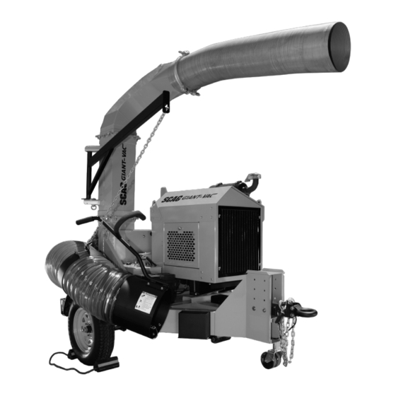
TRUCK LOADER
Industrial Tow Behind
Model:
TLB25-48KBD
PART NO. 03371
PRINTED 8/2014
PRINTED IN USA
Advertisement
Table of Contents

Summary of Contents for Scag Power Equipment TLB25-48KBD
- Page 1 TRUCK LOADER Industrial Tow Behind Model: TLB25-48KBD Congratulations on owning a Scag Giant-Vac truck loader! This manual contains the operating instructions and safety information for your Scag Giant- Vac truck loader. Reading this manual can provide you with assistance in maintenance and adjustment procedures to keep your truck loader performing to maximum efficiency.
- Page 2 CONCERN, PRUDENCE, AND PROPER TRAINING OF THE PERSONNEL INvOLvED IN THE OPERATION, TRANSPORT, MAINTENANCE, AND STORAGE OF THE EqUIPMENT. This manual covers the operating instructions and illustrated parts list for: TLB25-48KBD with a serial number of 013A00001 to 013A99999 Always use the entire serial number listed on the serial number tag when referring to this product.
-
Page 3: Table Of Contents
Table of Contents Table of Contents SECTION 1 - GENERAL INFORMATION ...................1 1.1 INTRODUCTION ............................1 1.2 DIRECTION REFERENCE ...........................1 1.3 SERvICING THE ENGINE AND DRIvE TRAIN COMPONENTS ..............1 1.4 SYMBOLS ..............................2 SECTION 2 - SAFETY INFORMATION ..................3 2.1 INTRODUCTION ............................3 2.2 SIGNAL WORDS ............................3 2.3 BEFORE OPERATION CONSIDERATIONS ....................3 2.4 OPERATION CONSIDERATIONS ........................5... - Page 4 Table of Contents SECTION 6 - ILLUSTRATED PARTS LIST ................20 6.1 SCAG GIANT-vAC APPROvED ATTACHMENTS AND ACCESSORIES..........20 NOTES ................................21 INTAKE AND DISCHARGE ASSEMBLY ......................22 IMPELLER HOUSING AND TRAILER ASSEMBLY..................24 IMPELLER DRIvE ASSEMBLY ........................26 KUBOTA ENGINE ASSEMBLY ........................28 FUEL AND ELECTRICAL SYSTEM ........................30 TLB25 - TRUCK LOADER DECALS ........................32 LIMITED WARRANTY - TRUCK LOADERS .................Inside Back Cover...
-
Page 5: General Information
Section 1 GENERAL INFORMATION INTRODUCTION WARNING Your Scag Giant-Vac product was built to the highest standards in the industry. However, the prolonged life For pictorial clarity, some illustrations and figures and maximum efficiency of your truck loader depends on in this manual may show shields, guards or plates you following the operating, maintenance and adjustment open or removed. -
Page 6: Symbols
Section 1 SYMBOLS SYMBOL DESCRIPTION SYMBOL DESCRIPTION Choke Transmission On/Start Spring Tension on Idler Off/Stop Spinning Fan Blades Thrown Object Hazard Fast Slow Continuously Variable - Linear Pinch Point 481039S Keep Bystanders Away Read Operator's Manual... -
Page 7: Safety Information
Section 2 SAFETY INFORMATION INTRODUCTION DANGER Your truck loader is only as safe as the operator. Carelessness or operator error may result in serious bodily injury or death. Hazard control and accident The signal word “DANGER” denotes that an extremely prevention are dependent upon the awareness, concern, hazardous situation exists on or near the machine that prudence, and proper training of the personnel involved in... - Page 8 Section 2 DO NOT operate the machine under the influence of Keep flammable objects (cigarettes, matches, etc.), alcohol or drugs. open flames and sparks away from the fuel tank and fuel container. Use only approved containers. Before and during reverse operation, look behind and down for small children and/or pets.
-
Page 9: Operation Considerations
Section 2 OPERATION CONSIDERATIONS Before attempting to start the engine, inspect the machine, inlet hose, discharge, debris receiver box, shields and safety devices for any damage. Correct This truck loader is designed for use at highway speeds in any problems before operating. normal conditions. -
Page 10: Maintenance Considerations & Storage
Section 2 DANGER REAR SUPPORT DO NOT run the engine inside a building or a confined area without proper ventilation. Exhaust fumes are hazardous and contain carbon monoxide which can cause brain injury and death. SPRING LATCH Keep hands and feet away from all other moving parts. -
Page 11: Safety And Instructional Decals
Section 2 SAFETY AND INSTRUCTIONAL DECALS 484983 485139 485122 485126 Avoid injury from burns - Shut o engine - Allow to cool several minutes - Remove cap slowly - Do not over ll 484292 DIESEL FUEL ONLY 484292... -
Page 12: Specifications
Starter ........................Electric Starting with Solenoid Shift IMPELLER Impeller Diameter ..........................Balanced 25" Steel Number of Blades ..........................4 - Blade, 1/2" CFM (cubic feet / min.) - TLB25-48KBD ........................7318 Wear Liner ................................1/4" Steel Intake Hose ................................7' x 16" Discharge ................................6' x 12"... - Page 13 Section 3...
-
Page 14: Operating Instructions
Section 4 OPERATING INSTRUCTIONS Ignition Switch (Figure 4-1). The ignition switch CAUTION is used to start the engine and has three positions; OFF, ON, and START. Engine Throttle Control (Figure 4-1). Used to Do not attempt to operate this machine unless control the engine speed. -
Page 15: Initial Run-In Procedures
Section 4 CONNECTING TO TOW vEHICLE Safety Chains (Figure 4-1). Used to connect to the tow vehicles cradle draw bar in criss-cross fashion in case of an accidental disconnect. Back the tow vehicle up to the truck loader. Rear Support Leg (Figure 4-1). Used to support Raise or lower the tongue jack until the pintle ring on the truck loader when disconnected from the tow... -
Page 16: Starting The Engine
Section 4 OPERATION This truck loader has been designed to pick up dry organic debris such as leaves, grass clippings, shavings and small amounts of sand. Vacuuming hard non-organic material will affect the life of your machine. Sand is abrasive and will produce wear of items including the blower housing, wear liners, impeller and nose cone. -
Page 17: Hillside Operation
Section 4 When operating, instruct the operator to stay to the To prevent tipping or loss of control, keep all side of the machine, never in front or behind. movements on slopes slow and gradual. Do not turn on slopes unless necessary, and then WARNING turn slowly and down hill when possible. -
Page 18: After Operation
Section 4 Crank down the tongue jack until the pintle ring on the unit clears the pintle hook on the tow vehicle. Pull and turn the spring latch to unlock the pin securing the rear support leg in the transport position. -
Page 19: Removing Clogged Material
Section 4 Keep the entire machine clean to inhibit serious heat damage to the engine. DANGER To avoid injury from burns, allow the engine to cool before removing the fuel tank cap and refueling. Check the tire pressure. Adjust pressure if necessary. -
Page 20: Maintenance
Section 5 MAINTENANCE MAINTENANCE CHART - RECOMMENDED SERvICE INTERvALS HOURS PROCEDURE COMMENTS BREAK-IN 100 200 500 (FIRST 10) Check all hardware for tightness Check impeller drive belt tension See Section 5.5 S e e e n g i n e o p e r a t o r ' s Check engine oil level manual *Clean truck loader... -
Page 21: Engine Oil
Section 5 ENGINE OIL Never store the machine or fuel container where there is an open flame, spark or pilot light such as on a water heater or other appliances. A. CHECKING ENGINE CRANKCASE OIL LEvEL Never fill containers inside a vehicle or on a truck or trailer bed with a plastic liner. -
Page 22: Impeller Shaft Bearings And Engine Stub Shaft
Section 5 CHECK BELT TENSION HERE ENGINE MOUNTING BOLTS Figure 5-1. Impeller Drive Belt Tension To adjust the impeller drive belt tension, loosen the four engine mounting bolts. See Figure 5-2. JAM NUTS & Loosen the jam nuts on all four adjustment studs. ADJUSTMENT STUDS See Figure 5-2. -
Page 23: Wheels & Tires
Section 5 Apply grease to the two engine stub shaft grease fittings located on the back of the engine every 50 hours or weekly, whichever comes first, of operation. See Figure 5-3. GREASE FITTINGS GREASE FITTINGS Figure 5-3. Impeller Shaft Grease Fittings WHEELS &... -
Page 24: Illustrated Parts List
Section 6 ILLUSTRATED PARTS LIST SCAG GIANT-vAC APPROvED ATTACHMENTS AND ACCESSORIES. Attachments and accessories manufactured by companies other than Scag Giant-Vac are not approved for use on this machine. Scag Giant-Vac approved attachments and accessories: • Truck Loader Light Kit (p/n 9602) •... -
Page 25: Notes
Section 6 NOTES... -
Page 26: Intake And Discharge Assembly
Section 6 INTAKE AND DISCHARGE ASSEMBLY... - Page 27 Section 6 INTAKE AND DISCHARGE ASSEMBLY Ref. Part No. Description 484939-04 Hose, Metal Galv. Interlock 12" X 72" 485061 Double Bolt Clamp, 12" 452529 Elbow, Exhaust - TLB25 04001-71 Bolt, Hex Head 1/2-13 x 1-1/2" 04040-13 Flatwasher, 1/2-.562 x 1.375 x .109 426327 Bracket, License Plate 04021-07...
-
Page 28: Impeller Housing And Trailer Assembly
Section 6 IMPELLER HOUSING AND TRAILER ASSEMBLY... - Page 29 Section 6 IMPELLER HOUSING AND TRAILER ASSEMBLY Ref. Part No. Description 485105 Pintle Ring, 3" 485104 Ball Coupler, 2-5/16" (optional) 04001-204 Bolt, Hex Head 5/8-11 x 4-3/4" Grade 8 04043-09 Flatwasher, 5/8-.656 x 1.312 x 0.95 HD 04021-23 Nut, Elastic Stop 1/2-13 04040-13 Flatwasher, 1/2-.562 x 1.375 x .109 04021-07...
-
Page 30: Impeller Drive Assembly
Section 6 IMPELLER DRIvE ASSEMBLY 33 35... - Page 31 Section 6 IMPELLER DRIvE ASSEMBLY Ref. Part No. Description 484992 Bushing, Tapered Lock SK 1-1/2" 04063-34 Key, 3/8 x 3/8 x 2-1/4" 484991 Pulley, Sheave 3V6.5 x 5 SK 04001-131 Bolt, Hex Head 5/8-11 x 1-3/4" 04030-07 Lockwasher, 5/8" Spring 04043-06 Flatwasher, 5/8-.688 x 1.75 x .134 HD 04001-183...
-
Page 32: Kubota Engine Assembly
Section 6 KUBOTA ENGINE ASSEMBLY *Not Shown Engine Oil Drain - p/n 485306 Coolant Over-Flow Bottle - p/n 485303... - Page 33 Section 6 KUBOTA ENGINE ASSEMBLY Ref. Part No. Description 462727 Enclosure, Side Panel 485297 Rain Cap, Exhaust 485296 Elbow, Exhaust 485298 Clamp, Muffler 2.0" 04013-03 Bolt, Hex Head 5/16-18 x 3/4" Ser. Flg. 04129-01 Thumb Screw, 5/16-18 x 5/8" 426691 Enclosure, Cover 426690 Bracket, Control Panel...
-
Page 34: Fuel And Electrical System
Section 6 FUEL AND ELECTRICAL SYSTEM To Starter To Ground 12 22 22 12... - Page 35 Section 6 FUEL AND ELECTRICAL SYSTEM Ref. Part No. Description 484989 Battery Box, GRP24 481176-08 Battery Cable, Red 481176-13 Battery Cable, Black 482283 Battery (not available thru Scag Giant-Vac) 04021-08 Nut, Elastic Stop 1/4-20 04040-14 Flatwasher, 1/4-.312 x .750 x .065 04011-11 Screw, #10-32 x .56 HDHW Shakeproof 485053...
-
Page 36: Tlb25 - Truck Loader Decals
Section 6 TLB25 - TRUCK LOADER DECALS 485115 484984 484983 485139 485122 ULTRA LOW WARNING INSTALL BELT COVER BEFORE SULFUR FUEL ONLY OPERATING MACHINE READ OPERATOR'S MANUAL 483402 484739 484739 485126... -
Page 37: Limited Warranty - Truck Loaders
LIMITED WARRANTY - TRUCK LOADERS Any part of the Truck Loader manufactured by Scag Giant-Vac and found, in the reasonable judgment of Scag Giant-Vac, to be defective in materials or workmanship, will be repaired or replaced by an Authorized Scag Giant-Vac Service Dealer without charge for parts and labor during the periods specified below.