
Summary of Contents for schweisskraft EASY-MIG 201 i MULTI
- Page 1 Operating Instructions MIG/MAG Inverter EASY-MIG 201i MULTI EASY-MIG 211i MULTI EASY-MIG 211i MULTI EASY-MIG 201i MULTI...
-
Page 2: Table Of Contents
Fax: 0049 (0) 951 - 96555-55 5.2 Packaging ............9 5.3 Storage ............... 9 E-Mail: info@schweisskraft.de 6 Principle of operation ......9 Internet: www.schweisskraft.de 6.1 Principle of the metal inert gas welding process.. 10 6.2 Functional principle of wire feeding ....10 6.3 Torch equipment.......... -
Page 3: Introduction
You have made a good choice by purchasing the 1.3 Limitation of liability SCHWEISSKRAFT MIG/MAG inverter welder. Read the operating instructions carefully before All information and instructions in the operating instructi- commissioning. -
Page 4: Obligations Of The Operating Company
Safety Obligations of the operating company If the welding device is used for commercial purposes, the operating company of the welding device must com- DANGER! ply with the legal working safety regulations. This combination of symbol and signal word indicates Therefore, the safety notes in this operating manual, as an immediately dangerous situation. -
Page 5: Personal Protective Equipment
Safety The personal protective equipment is explained in the WARNING! following paragraph: Danger in case of insufficient quali- fication of the staff! Welders face protection shield or Insufficiently qualified persons cannot estimate the helmet with welder's face protec- risks while using the welding device and expose tion shield themselves and others to the danger of severe or The welding shield, which is wear on the head and in... - Page 6 Safety - Before replacing wearing parts of the torch, the wel- - This welding equipment complies with the technical product standards for exclusive use in commercial ding device must be switched off and disconnected and professional environments. Compliance with the from the mains supply.
-
Page 7: Safety Labels
Intended use Additional safety precautions 2.7 Safety data sheets During welding work Safety data sheets on hazardous materials can be ob- - in environments with increased risk of electric tained from your specialist dealer or by calling +49 shock; (0)951/96555-0. Specialist dealers can find safety data - in confined spaces;... -
Page 8: Reasonably Foreseeable Misapplication
Technical Data Technical Data 3.1 Reasonably foreseeable misappli- cation Parameter EASY-MIG Any use beyond or different from the intended use is 201i considered misuse. EASY-MIG 211i Possible misuses can be: Electrical connection 230 V - Use in areas with hazardous substances, Fuses slow-blow 16 A - Risk of explosion or fire. -
Page 9: Type Plate
Transport, packaging, storage 4.1 Type plate The film is made of polyethylene (PE) and the cushioned parts of polystyrene (PS). Deliver these substances to a The most important information on the operation and collection point for recyclable materials or to the waste performance of the welding unit are summarized on the disposal company which looks after your region. -
Page 10: Principle Of The Metal Inert Gas Welding Process
Principle of operation 6.1 Principle of the metal inert gas wel- 6.2 Functional principle of wire feeding ding process The wire conveyor unrolls the weldment wound on a bas- ket or mandrel spool and conveys it through the hose The principle of MIG / MAG welding is that a metal wire is package to the torch. -
Page 11: Operation
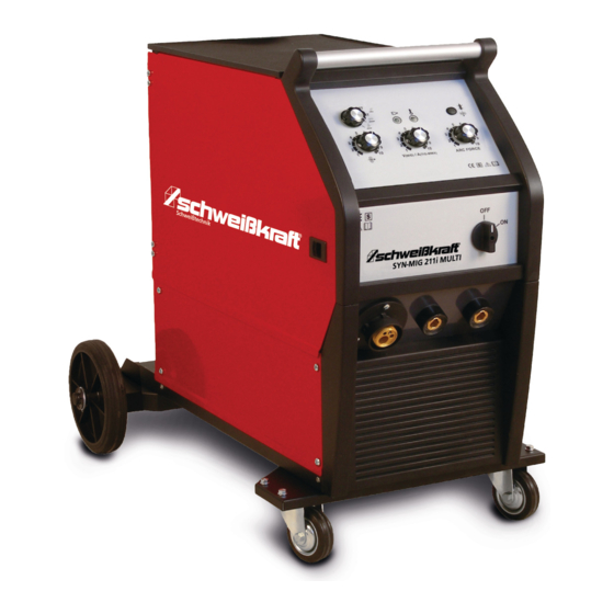
Operation Guide spiral DANGER OF FIRE! The wire guide spiral is pulled through the hose as- sembly of the burner, in her the welding wire is passed to - Avoid spreading open fire, which can be triggered the burner. by sparks, slag and glowing material. - Fire protection devices must be near the workplace. - Page 12 Wire feed: 10 L (EASY-MIG 201i MULTI) 7.1.3 Device view EASY-MIG 211i MULTI SSJ-29 (EASY-MIG 211i MULTI) Feed roller: 30 mm 7.1.2 Device view EASY-MIG 201i MULTI Schweisskraft EASY-MIG 211i MULTI Schweisskraft EASY-MIG 201i MULTI Fig. 7: Device view EASY-MIG 201i MULTI Fig.
-
Page 13: Scope Of Delivery
Operation 7.2 Scope of delivery Before making the electrical connections, check that the data on the type plate of the welding unit corresponds to - Torch SMB 15, 3m the mains voltage and frequency at the installation site. - Ground cable 3m, 16 mm² The welding unit may only be used with a power connec- tion with earthing plugs installed by an authorised spe- - Feed roller 0,8/1,2 mm... -
Page 14: Inserting The Welding Rod Reel And Wire Guide
Operation - Provide and secure gas cylinder. If necessary, it can 7.6 Inserting the welding rod reel and be loaded onto the storage surface of a trolley; wire guide weight max 30 kg. - After removing the protective cap, briefly open the cylinder valve in the direction away from the body in Mandrel or reel spool order to remove any impurities. -
Page 15: Weld Preparation
Operation - Do not point the burner at body parts. Groove shapes - Do not approach the burner to the bottle. - The contact tube and the nozzle must be reattached to the burner. - Check that the wire is fed evenly; set the roller pres- sure and the absorption brake to the minimum values and check whether the wire slips in the groove and whether the wire coils loosen when the... -
Page 16: Welding
Operation 7.8 Welding Change polarity: Some cored wires require reverse polarity for welding. CAUTION! The figure shows the inner connections. Flux-cored wire allows welding without gas, but the process and results - Never point the torch at body parts. are unprofessional. - Never approach the torch to the bottle. - Page 17 Operation Step 4: Arc Force current adjustment: The burner is pushed. Flat penetration, wide seam pat- Set the desired value with the rotary knob for the tern. Good suitability for welding thin sheets, low distor- Arc Force current setting. If the welding voltage tion due to lower heat input.
-
Page 18: Description And Use Of Different Arc Types
Maintenance 7.9 Description and use of different arc Protective gas types The protective gas has the task to shield the molten bath from the atmosphere. It influences the electrical conduc- The short arc (KLB)is used for thin sheets, forced and tivity, the heat conduction and the heat content of the root welds in the low power range. -
Page 19: Special Maintenance
Troubleshooting Torch - Avoid directing the compressed air jet at the electro- nic cards. If necessary, clean them with a particu- larly soft brush or a suitable solvent. NOTE! - If possible, check that the electrical connections are Follow the enclosed torch instructions for all adjust- tight and that the cable insulation is undamaged. - Page 20 Troubleshooting Fault Possible cause Solution Feed motor doas not 1. Mains voltage is missing 1. Check mains connection 2. Mains voltage switch is at zero position 2. Set voltage level 3. Burner switch not actuated 3. Press burner switch 4. Fuse defective 4.
-
Page 21: Disposal, Recycling Of Old Equipment
Disposal, Recycling of old equipment 10 Disposal, Recycling of old 11 Spare parts equipment DANGER! In your own interests and in the interest of the environ- Danger of injury due to use of wrong spare parts! ment, please ensure that all components of the machine are disposed of in the proper and approved way. -
Page 22: Spare Parts Drawings
Spare parts 11.2 Spare parts drawings In case of service, the following drawings shall help to identify the necessary spare parts. If necessary, send a copy of the parts drawing with the marked components to your authorised dealer. Spare parts drawing EASY-MIG 201i MULTI Fig. - Page 23 Spare parts Spare parts drawing EASY-MIG 211i MULTI Fig. 12: Spare parts drawing EASY-MIG 211i MULTI Spare parts list EASY-MIG 211i MULTI Pos. Designation Pos. Designation Pos. Designation Main board Base plate Rubber surface Choke Front panel Gas bottle holder PFC Choke Distance plate Fixing tape...
-
Page 24: Electrical Circuit Diagrams
Electrical circuit diagrams 12 Electrical circuit diagrams Electric circuit diagram EASY-MIG 201i MULTI Fig. 13: Electrical circuit diagram EASY-MIG 201i MULTI EASY-MIG | Version 1.04... - Page 25 Electrical circuit diagrams Electric circuit diagram EASY-MIG 211i MULTI Fig. 14: Electrical circuit diagram EASY-MIG 201i MULTI EASY-MIG | Version 1.04...
-
Page 26: Ec Declaration Of Conformity
13 EC Declaration of Conformity for the following designated product Manufacturer/distributing company: Stürmer Maschinen GmbH Dr.-Robert-Pfleger-Straße 26 D-96103 Hallstadt ® Product group: Schweisskraft Schweißtechnik Type of machine: MIG/MAG Inverter Designation of welding device *: EASY-MIG 201i MULTI Item number *:... -
Page 27: Notes
Notes 14 Notes EASY-MIG | Version 1.04... - Page 28 www.schweisskraft.de...
Need help?
Do you have a question about the EASY-MIG 201 i MULTI and is the answer not in the manual?
Questions and answers