Table of Contents
Advertisement
For the latest version – check:
http://www.csntechnologies.net/sat/manual
17 Nov 2022
S.A.T. Instruction Manual
* DO NOT ATTACH THE S.A.T. TO YOUR YAESU ROTATOR
UNTIL YOU COMPLETE THE CALIBRATION STEPS DESCRIBED
BELOW
Introduction
The S.A.T. is a novel and completely self contained device used to predict and track satellite passes
while simultaneously controlling an antenna rotator and tuning a transceiver. Once connected to
mobile device or computer through it's built it WiFi, all control is performed through any web
browser.
Get Familiar
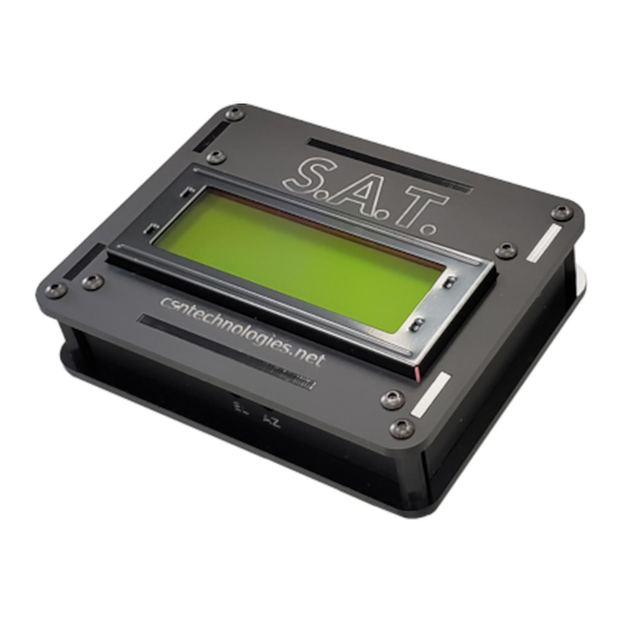
LCD
The built in LCD displays information depending on the state of the S.A.T. For example, the IP address,
serial number and firmware version are displayed when the S.A.T. is idle. When actively tracking, the
satellite name, azimuth, elevation, range and range rate and AOS/LOS is shown. Other status message
are also available such as during TLE and firmware updates.
Advertisement
Table of Contents

Subscribe to Our Youtube Channel
Summary of Contents for CSN S.A.T.
- Page 1 For the latest version – check: http://www.csntechnologies.net/sat/manual 17 Nov 2022 S.A.T. Instruction Manual * DO NOT ATTACH THE S.A.T. TO YOUR YAESU ROTATOR UNTIL YOU COMPLETE THE CALIBRATION STEPS DESCRIBED BELOW Introduction The S.A.T. is a novel and completely self contained device used to predict and track satellite passes while simultaneously controlling an antenna rotator and tuning a transceiver.
- Page 2 PORTS The ports for connecting power, the rotator and your radio are location along to the top of the S.A.T. Use the guide to identify the various connections. RADIO CI-V CONNECTION The RIG CONTROL port on your S.A.T. plugs into your radio with the provided Tip-Ring-Sleve cable. Refer to the images on the right to find the CI-V or Remote jack on your radio.
- Page 3 Icom IC-9700 Icom IC-9100 ROTATOR CONNECTION Plug the Mini-DIN connector into the S.A.T. and the full size DIN connector to the back of the rotator control box. Refer to the image for the correct port. * Do not connect the rotator until you read the calibration procedure below.
- Page 4 Apply Power and Boot Attach USB Your S.A.T. is powered by 5V through any standard USB port. Using the provided Micro-USB cable, attached your S.A.T. to a USB port. Since the S.A.T. is an extremely low power device, almost any USB power source will work including computers and laptops and of course, cell phone/mobile device chargers.
- Page 5 The LCD will light up and the S.A.T. will beep once or twice while it's initializing. Connect to the S.A.T. Determine IP Address During startup the S.A.T. will try to connect to a WiFi network if one has been configured. If it cannot connect to a WiFi network then it will beep twice and start its internal WiFi Access Point.
- Page 6 Open the Dashboard Using your mobile device's web browser, navigate to the IP address displayed on the LCD screen. For example: http://192.168.4.1 The S.A.T. dashboard will open on your device.
- Page 7 The S.A.T. Dashboard The S.A.T. dashboard is seperated into four main areas. Track Panel While tracking, this panel displays essential satellite information and current antenna position information. Current wind speed and direction is also displayed for your location. Entering a satellite name or catalog number into the Name box and clicking Search will start tracking...
- Page 8 the entered satellite, if it's found in the loaded TLE file. The Satellite Status link will open the Amsat Satellite Status Page in a new window . The SatNOGS link will open the excellect SatNOGS map for the currently tracked satellite. Available Buttons: NEXT PASSES - Predict and display current and future passes.
- Page 9 Polar The polar view takes some getting used to but contains a lot of useful information. The outer ring is horizon and the center is directly overhead. North is towards the top. This display shows the satellite track across the sky as well as the AOS and LOS azimuth and current antenna position. The color of the track indicates if the satellite is in sunlight or shadow - yellow for sunlight and green for shadow.
- Page 10 Radio Panel Displays radio controls and available satellite transponders. Top Row Buttons: ENABLE - Enable or disable rig control. A Green button means the rig is enabled and will be controlled. If red then it will not. LOCK VFO - The S.A.T. keeps the uplink frequency in step with the downlink as you make changes with the VFO knob.
-
Page 11: Manual Control Panel
Option Buttons On small screen devices such and phones and tablets the buttons will be found at the bottom of the page. On full size devices the button will location across the top of the page. The various options are described in detail below: CONTROL - Manually control the rotator. - Page 12 Elevation is not changed with this feature. PAN Section On the right side of the panel are four pan buttons. Press and hold the buttons to move the appropriate axis. These work similar to the physical movement button on your rotator control box. Up button - Move elevation up.
- Page 13 ROTATOR PANEL The Rotator Panel is where you will find the rotator and satellite tracking settings: TYPE - Choose the rotator model to use. The S.A.T. natively supports the Yaesu G5500, G5400 and G5600 with the included cable. PstRotator is also supported. IP ADDRESS - For PstRotator enter the IP address of the computer where PstRotator is running.
-
Page 14: Network Panel
ALARM - The S.A.T. contains a built in beeper that will sound when the satellite reaches a set amount of time prior to AOS. Enter the minutes and seconds here at which time you would like to hear the alarm. Enter 00:00 to disable the alarm. PLAY ALARM ON - The AOS alarm can be sounded on the S.A.T. - Page 15 restart and attempt to connect to the WiFi network. Look at the LCD to see the IP address obtained and then connect to it using your mobile devices. Once connected you can update the TLEs and perform firmware updates. PORTS - Your S.A.T. is visible on the network as a HamLib compatible rotator and rig server. Use these fields to change the default listening ports.
- Page 16 LOCATION PANEL Enter operating location and other settings. CALLSIGN - Enter your callsign here to be used in the QSO logging feature. GRID - Enter your gridsquare to automatically calculate your latitude and longitude. It's also used the the QSO logging feature. LAT,LON - Enter your precise latitude and longitude.
- Page 17 PASS LOG Click this button to display a history of the satellites that have been tracked and have risen above the horizon. WINDOW This button will open a separate browser window that you can move to another monitor. A single item can be displayed such as the Map, one of the charts, general data, etc.
-
Page 18: About Panel
CLEAR - Remove all satellites from the schedule. LOAD - Load the saved schedule. SAVE - Save the current schedule. CLOSE - Close the window. ABOUT PANEL The About panel display firmware versions and copyright information. Click the CHECK FOR UPDATE button next to the firmware version to check for updates (Internet connection is required). -
Page 19: Manual Calibration
Calibration procedure below. *Note: Not all rotator choices support auto-calibration. Manual Calibration Now click on the VOLTS button (You can close the message that opens, it's just a reminder of these instructions). The sensed voltage from the rotator control box is now displayed on the LCD. Manually increase your azimuth and watch the voltage on the LCD. - Page 20 Using your S.A.T. Start Tracking Be sure to configure your Location, Rotator and Radio using the instructions above before using your S.A.T. Of course, make sure your TLE's are up to date for best results. There are a few ways to start tracking a satellite. The quickest is to type the name or catalog number into the search field and click SEARCH.
- Page 21 While Tracking While tracking the page will automatically update about every 2 seconds. The S.A.T. will automatically determine if it should flip the antenna to track the satellite continuously through it's pass. (REVERSE) will be displayed in the antenna position line to indicate this. The maps and graphs will also start updating.
-
Page 22: Best Practice
* In order to use the PL Tone properly on your Icom, ensure the following setting is set to ON (DUP) Menu -> Set -> Function -> Auto Repeater When tracking starts the first transponder in the list is automatically selected. Your radios VFOs and modes will be set up and the center frequencies will be selected, adjusted for doppler. - Page 23 the passband. That should be it! Adding and Editing Transponders You can add new transponders to satellites by clicking on the Add button. You can also edit existing transponders by clicking on frequency itself in the transponder list. Each one will open the transponder edit window show at the right.
-
Page 24: Advanced Features
Advanced Features Favorites List Usually the standard TLEs from the internet contain far more satellites than you're interested in. More satellites equals more time to search and more time to predict future passes. In the VIEW ALL page, each satellite has a checkbox next to it. Check of each satellite you are interested in and click SAVE at the bottom. - Page 25 Your S.A.T. contains a call log feature with internet lookups and macros. Press the CALL LOG button at the bottom of the page to open the call log entry window. If you have set your QRZ login credentials in the LOCATION page then you can use the LOOKUP button to automatically fill in the log entry fields.
- Page 26 that opens, select the WSJT/JTDX Setup tab. In the upper WSJT-X section check the enable button. Choose a port to received log entries. The IP address can be ignored. Log4OM - Open the configuration panel and choose Connections from the tree on the left. Now on the right side, click UDP.
- Page 27 In GPredict you can set up the rotator and rig in the interfaces section. The standard ports are enabled by default on the S.A.T., 4533 for the rotator and 4532 for rig. Note that PTT is not yet supported. When tracking with a PC program do not simultaneously track with the S.A.T., confusion will ensue! GPS Operation If your S.A.T.
- Page 28 When enabled the LCD of the S.A.T. changes to show current time, grid, acquired satellites, lattitude and longitude. When moving from oen grid to another the S.A.T. will beep three times to let you know that you have crossed a grid boundary. (A six character grid is displayed but the alarm sounds when crossing 4 character grid boundaries).
- Page 29 AMSAT nasabare.txt (updated weekly) http://www.amsat.org/tle/current/nasabare.txt CSN nasabare.txt (a copy of AMSATs nasabare.txt) - http://www.csntechnologies.net/SAT/nasabare.txt CSN csnbare.txt (same satellites as nasabare.txt but generated with Celestrack data, updated daily) - http://www.csntechnologies.net/SAT/csnbare.txt How do I factory reset? You can find the Factory Reset button in the About box in the web interface.
- Page 30 VFO's and move up and down the band with the VFO knob and the SAT will keep everything in sync and adjusted for doppler. Copyright © CSN Technologies Inc. 2022 APRS is a registered trademark Bob Bruninga, WB4APR...
Need help?
Do you have a question about the S.A.T. and is the answer not in the manual?
Questions and answers